Not available:
| № | Part code | Name | Part Information |
| 200319-P29 | Bolt M10x1.5x50 | Quantity per Quantity for all modifications 1 Galvanizing and passivation coating (zinc with chromating) | Not available |
| 201418-P29 | Bolt M6x1x16 | Quantity per Quantity for all modifications 1 Galvanizing and passivation coating (zinc with chromating) | Not available |
| 201460-P29 | Bolt M8x1.25x30 | Quantity per Quantity for all modifications 1 Galvanizing and passivation coating (zinc with chromating) | Not available |
| 201505-P29 | Bolt M10x1.5x45 | Quantity per Quantity for all modifications 2 Coating galvanized and passivated (zinc with chromating) | Not available |
| 201544-P29 | Bolt M12x1.75x40 | Quantity per Quantity for all modifications 1 Galvanizing and passivation coating (zinc with chromating) | Not available |
| 220081-P29 | Screw M5x0.8x18 | Quantity per Quantity for all modifications 4 Galvanizing and passivation coating (zinc with chromating) | Not available |
| 250-1602010 | Clutch pedal assembly | Quantity per Quantity for all modifications 1 Model 250 Group Clutch Subgroup Pedal and clutch control drive Part number 010 | Not available |
| 250-1602015 | Clutch pedal | Quantity per Quantity for all modifications 1 Model 250 Group Clutch Subgroup Clutch control pedal and drive Part serial number 015 | Not available |
| 250-1602016 | Pedal platform | Quantity per Quantity for all modifications 1 Model 250 Group Clutch Subgroup Clutch control pedal and drive Part serial number 016 | Not available |
| 250-1602021 | Pad pad | Quantity per Quantity for all modifications 1 Note 1 - purchased product 2 - not shown in the figure Model 250 Group Clutch Subgroup Clutch control pedal and drive Part serial number 021 | Not available |
| 250-1602022 | Pedal bushing | Quantity per Quantity for all modifications 2 Note 1 - purchased product 2 - not shown in the figure Model 250 Group Clutch Subgroup Clutch control pedal and drive Part serial number 022 | Not available |
| 250-1602046 | Pedal pin | Quantity per Quantity for all modifications 1 Model 250 Group Clutch Subgroup Clutch control pedal and drive Part serial number 046 | Not available |
| 250-1602065 | Washer | Quantity per Quantity for all modifications 1 Model 250 Group Clutch Subgroup Pedal and clutch control drive Part number 065 | Not available |
| 250-1602068 | Pedal bracket | Quantity per Quantity for all modifications 1 Model 250 Group Clutch Subgroup Clutch control pedal and drive Part serial number 068 | Not available |
| 250-1602094-10 | Spring | Quantity per Quantity for all modifications 1 Model 250 Group Clutch Subgroup Pedal and clutch control drive Serial number of part 094 Additionally Not interchangeable with a part previously released under the same number | Not available |
| 250-1602217 | Lever arm | Quantity per Quantity for all modifications 1 Model 250 Group Clutch Subgroup Pedal and clutch control drive Part number 217 | Not available |
| 250-1602312 | Hose | Quantity per Quantity for all modifications 1 Note 1 - purchased product 2 - not shown in the figure Model 250 Group Clutch Subgroup Clutch control pedal and drive Part serial number 312 | Not available |
| 250-1602384-10 | Spring | Quantity per Quantity for all modifications 1 Model 250 Group Clutch Subgroup Pedal and clutch control drive Part serial number 384 Additionally Not interchangeable with a part previously released under the same number | Not available |
| 250-1602385-10 | Spring bracket | Quantity per Quantity for all modifications 1 Model 250 Group Clutch Subgroup Pedal and clutch control drive Part serial number 385 Additionally Not interchangeable with a part previously released under the same number | Not available |
| 250-1602386 | Spring lever | Quantity per Quantity for all modifications 1 Model 250 Group Clutch Subgroup Clutch pedal and drive Part serial number 386 | Not available |
| 250510-P29 | Nut M8 | Quantity per Quantity for all modifications 2 Coating galvanized and passivated (zinc with chromating) | Not available |
| 250640-P29 | Nut M20x1.5 | Quantity per Quantity for all modifications 1 Galvanizing and passivation coating (zinc with chromating) | Not available |
| 251-1602399 | Pipeline | Quantity per Quantity for all modifications 1 Model 251 Group Clutch Subgroup Clutch control pedal and drive Part serial number 399 | Not available |
| 251086-P29 | Nut M5x0.8 | Quantity per Quantity for all modifications 4 Galvanizing and passivation coating (zinc with chromating) | Not available |
| 252019-P29 | Washer 20 | Quantity per Quantity for all modifications 1 Galvanizing and passivation coating (zinc with chromating) | Not available |
| 256B-1108022 | Pedal spring | Quantity per Quantity for all modifications 1 Model 256B Group Engine power system Subgroup Carburetor control (accelerator - fuel supply control) Part serial number 022 | Not available |
| 258039-P29 | Cotter pin 3x20 | Quantity per Quantity for all modifications 1 Galvanizing and passivation coating (zinc with chromating) | Not available |
| 258052-P29 | Cotter pin 3.6x20 | Quantity per Quantity for all modifications 2 Coating galvanized and passivated (zinc with chromating) | Not available |
| 258053-P29 | Cotter pin 4x25 | Quantity per Quantity for all modifications 1 Galvanizing and passivation coating (zinc with chromating) | Not available |
| 260-1602288 | Air distributor | Quantity per Quantity for all modifications 1 Model 260 Group Clutch Subgroup Pedal and clutch control drive Part number 288 | Not available |
| 260-1602290 | Master cylinder pipe | Quantity per Quantity for all modifications 1 Model 260 Group Clutch Subgroup Clutch control pedal and drive Part serial number 290 | Not available |
| 260-1602350 | Clutch release cylinder assembly | Quantity per Quantity for all modifications 1 Model 260 Group Clutch Subgroup Pedal and clutch control drive Part number 350 | Not available |
| 260-1602391 | Intermediate hose | Quantity per Quantity for all modifications 2 Note 1 - purchased product 2 - not shown in the figure Model 260 Group Clutch Subgroup Clutch control pedal and drive Part serial number 391 | Not available |
| 260-1602510 | Clutch master cylinder assembly | Quantity per Quantity for all modifications 1 Model 260 Group Clutch Subgroup Clutch pedal and drive Part serial number 510 | Not available |
| 260058-P18S | Finger 10x30 | Quantity per Quantity for all modifications 1 Coating without coating | Not available |
| 260058-P29 | Finger 10x30 | Quantity per Quantity for all modifications 1 Galvanizing and passivation coating (zinc with chromating) | Not available |
| 260091-P18S | Finger 12x45 | Quantity per Quantity for all modifications 2 Coating without coating | Not available |
| 260091-P29 | Finger 12x45 | Quantity per Quantity for all modifications 2 Coating galvanized and passivated (zinc with chromating) | Not available |
| 288002-P29 | Clamp | Quantity per Quantity for all modifications 4 Galvanizing and passivation coating (zinc with chromating) | Not available |
| 348136-P29 | Tip | Quantity per Quantity for all modifications 2 Coating galvanized and passivated (zinc with chromating) | Not available |
| 348518-P29 | Bolt M8x40 | Quantity per Quantity for all modifications 1 Galvanizing and passivation coating (zinc with chromating) | Not available |
Assembly and adjustment of the clutch
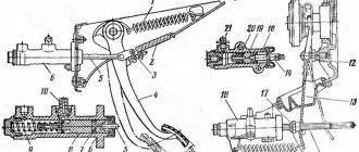
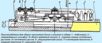
The pressure set should be assembled in the fixture shown in Fig. 235 and under hand press. The device consists of a stand having an installation dimension from the mating plane of the clutch casing to the plane of the pressure plate of 27 ±0.1 mm. In the center of the stand, a mandrel 8 is attached with a bolt 7 to adjust the control size of the pressure set B (see Fig. 33), equal to 64 ± 0.5 mm. The mandrel contains four floating thrust blocks 6 (see Fig. 235).
When installing the pressure set into the fixture, the crackers rest against the legs of the pull levers 4 and, depending on their position, protrude or sink relative to the surface of the mandrel. The length of the mandrel is chosen in such a way that when installed on the pull-out levers of the pressure set with a correctly adjusted control size, the crackers are flush with the surface of the mandrel. The control size of 64±0.5 mm of the clutch pressure set also includes the thickness of the thrust ring of the release levers, which is 6±0.1 mm, and since the pressure set is adjusted in a device without a thrust ring, it must be adjusted to a size reduced by this value, i.e. by 58±0.5 mm.
Assembly and adjustment are carried out in the following sequence:
- The pressure disk is placed on the stand 11 of the device with the working surface down, fixing it with four tenons in the grooves of the stand;
- A needle bearing is inserted into the pull-out levers 4 (20 needles in each hole). The needles are placed on CIATIM-201 lubricant or other grease corresponding to it;
- Forks 6 are installed on the pull-out levers (see Fig. 33);
- insert the fork axles;
- install the assembled levers into the grooves of the pressure disk lugs;
- insert the lever axes;
- put the thrust ring springs on the fork axles;
- secure the axes of the levers and forks with special locking washers, bending the middle of the apron jumper;
- Four loops 10 are put on the ends of the springs of the thrust ring 14;
- Place pressure springs 20 on the bosses of the pressure disk, having previously placed washers with thermal insulating gaskets 21 under them.
When using a pressure disk machined along the working surface by 1 mm, a steel washer 1 mm thick is placed under each pressure spring 20 (from the side of the casing guide cups) to maintain the clutch pressure.
Next, you need to place the clutch housing 19 on the guide pins of the device. All guide cups of the casing must fit into the pressure springs, and the threaded shanks of the forks of the pull-out levers into the holes of the casing. Using a press, it is necessary to press the casing with the mating surface to the device and secure it with bolts, and then release it from under the press. Screw the adjusting nuts 3 onto the threaded shanks of the forks, install a mandrel to adjust the position of the pull-out levers 4 and secure it with a bolt 7 (see Fig. 235). After this, use the adjusting nuts 3 to adjust the position of the pull-out levers 4 so that they all simultaneously touch the thrust blocks 16 of the mandrel. 8, which should be flush with its upper surface. This ensures a control dimension between the working surfaces of the pressure plate and the thrust ring when installing the thrust ring.
Plates 2 are placed on the adjusting nuts 3, then the locking strips and the support plates of the lever forks, after which all eight locking bolts are screwed in. After tightening the bolts, the forks of the pull-out levers should not have any axial play. The bolts are secured by bending the locking strips. Having installed a thrust ring on the pull-out levers, secure it with loops so that it simultaneously touches the supporting surfaces of all four levers.
The runout of the end of the thrust ring relative to the working surface of the pressure plate should not exceed 0.4 mm at a radius of 45 mm. Increased runout of these surfaces can lead to failure of the friction linings of the clutch driven disc and burns to the working surfaces of the flywheel and pressure plate.
Features of operation and technical characteristics of the KrAZ-260
The basic one was the KrAZ-260, which was manufactured by the plant since 1981.
On its basis, the 260A model was developed, equipped with a YaMZ-238N diesel engine. Centrifugal gasoline pumps and an additional fuel tank were not provided for it.
The 260V truck tractor is equipped with a specific coupling element, which is characterized by a shorter length at the end of the frame.
This modification can be used for a semi-trailer with full weight:
- on the road - up to 28 tons,
- without coating – up to 23 tons.
A separate design is represented by the extended chassis of the KrAZ-260G.
The manufacturer also developed and manufactured a prototype version of a truck tractor designed for an active road train. It was called KrAZ-260D, but it was produced in only two copies.
In addition, following the example of the KrAZ-255L1 device, an experimental timber carrier was produced. It was the KrAZ-260L, but it was replaced by the serial copy 6437, which stood out for changes in the chassis.
Types and frequency of maintenance of the KrAZ-6443 tractor
Car maintenance, based on frequency and volume of work performed, is divided into the following types: 1. Daily maintenance (DM). EO is carried out before leaving and upon returning the car from the line. When changing drivers on the line, they carry out work to inspect and check the technical condition of the vehicle.
2. Maintenance during the initial period of operation (after running-in):
the first post-break-in maintenance is performed once after the first 1000 km (Table 3);
the second post-break-in service is performed after the first 3000 km (Table 3).
3. Maintenance during the main period of operation:
TO-1 - maintenance No. 1, performed every 4000 km (Table 3);
TO-2 - maintenance No. 2 - is performed every 16,000 km (Table 3).
4. Seasonal maintenance - CO - is performed twice a year: when preparing the vehicle for operation in winter and summer (Table 3).
The maintenance frequency indicated above is established for operating the vehicle primarily in flat terrain on roads with asphalt or concrete pavement in good condition, outside of large cities. When operating the vehicle under other conditions, the mileage between regular maintenance services is reduced:
in mountainous areas - by 15%;
on roads in unsatisfactory condition - by 15%;
inside big cities - by 10%.
Modification options
For KrAZ-260 and its modifications there are some differences in parameters. For comparison, 260, 260G and 260V were selected.
The curb weight of these vehicles is 12.425, 11.210 and 10.9 tons, respectively. In this case, the total mass:
- 260 – 22 t,
- 260G – 21,680 t,
- 260V – 20.9 t.
Do you know the technical characteristics of the KrAZ-250, a truck used in both the military and construction industries? And here you will find a description of the 255 series of cars from the Kremenchug plant.
The permissible load on the saddle for all three vehicles is 9.5 tons. The total weight of the towed trailer can reach up to 10 tons for 260 and 260G, and up to 23 tons for 260V.
The base of KrAZ-260 and 260V is 6,000 mm, for 260G – 6,400 mm. The distance between the front axle and the middle axle is 4,600 mm and 5,000 mm, respectively.
For all modifications under consideration, the distance between the intermediate and rear axles will be 1,400 mm.
KrAZ-260
The development of the KrAZ-260 all-terrain truck began at the design bureau of the Kremenchug Automobile Plant in the 60s under the leadership of chief designer V.V. Tabolin. It was intended to replace the KrAZ-255B vehicle. The car received a new all-metal cabin (from the KrAZ-250) and tail. To improve visibility, the cabin was slightly pushed over the engine. This also made it possible to increase the length of the loading platform. A more powerful turbocharged YaMZ-238L engine is installed. All this made it possible to increase the load capacity by 1.5 tons. The car underwent comprehensive testing at NII-21 in Bronnitsy. Introduction into production was delayed due to the lack of capacity at the plant for the production of all-metal cabins. The first pilot production batch of KrAZ-260 was manufactured in 1979. Serial production began in 1981 and was carried out in parallel with the KrAZ-255B1. And it continued until 1993, after which it was replaced on the assembly line by the more advanced KrAZ-6322.
The KrAZ-260 vehicle is designed for transportation of various cargoes and personnel on roads of all categories and off-road. At airfields it is used for towing aircraft weighing up to 75 tons.
The KrAZ-260 vehicle has a hood layout. The cargo platform is metal with a rear opening side, equipped with folding benches, arches and an awning. To increase cross-country ability, permanent all-wheel drive, short front and rear overhangs, single-pitch tires, and a tire pressure regulation system were used. The power plant consists of an 8-cylinder V-shaped four-stroke multi-fuel turbocharged diesel engine YaMZ-238L (since 1984 YaMZ-238A). There is a pre-heater and a “Thermostart” device, which makes it easier to start the engine at low temperatures. There is no muffler in the exhaust system - part of the energy of the exhaust gases is absorbed by the supercharger turbine. The fuel supply is located in 2 main and 1 additional fuel tanks. The clutch is double-disc dry.