Adjusting the clutch release drive
The clutch release drive has two independent adjustments: adjustment of the free play of the clutch pedal and adjustment of the gap between the end of the rear cover of the valve body and the lock ring .
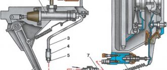
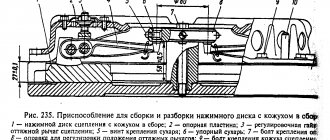
The gap between the end of the case back cover and the retaining ring is adjusted, if necessary, after control, through one TO-2. This gap (Fig. 35) should be equal to 3.5+0.2 mm. To adjust the gap, it is necessary to loosen the lock nut 11, rotate the fork 12 to establish the specified gap between the end of the rear cover 13 and the lock ring 10 and tighten the lock nut 11.
The free play of the clutch pedal, which should be 35-45 mm, is checked at each TO-1 with a ruler when the cabin is empty and there is no air in the pneumatic system, since if there is pressurized air in the booster, it is impossible to feel the amount of free play of the pedal.
Before you begin adjusting the clutch pedal free travel drive, you must make sure that the gap between the end of the rear cover of the valve body and the lock ring is within 3.5 + 0.2 mm.
Adjustment of the clutch pedal free play is carried out in the following sequence:
- disconnect plug 15 (see Fig. 34) and 12 from double-arm lever 11;
- pull lever 11 back (along the vehicle's direction) by the lower arm until it stops, while the misalignment of the hole in the upper arm of lever 11 and the hole in the cylinder rod fork should be 8-10 mm (no more than the diameter of the hole for the finger) at the lowest position of the cylinder piston, and the misalignment of the hole in the lower arm of the lever with the hole in the valve fork should be 5-6 mm (half the hole) while maintaining gap A;
- The length of rod 9 (see Fig. 34) and cylinder rod 14 is adjusted by rotating forks 8 and 12.
After adjustment, it is necessary to check the amount of free play of the pedal, which should be within 35-45 mm. If the possibility of restoring free play of the pedal has been exhausted, you need to move lever 11 by one slot (counterclockwise) and make the adjustment again
Source
Story
For that time, the truck was a real innovation. All the parts from which it was assembled had never been used before. Just look at the cabin, completely atypical, similar to popular European-made truck models of those years.
The short base and strong diesel engine, as well as the power steering and shock absorbers, hint at copying from foreigners. However, there are no wheel rims.
It is worth noting that not only the 504, but also other models of tractors in this series have been in great demand for several decades. It should be taken into account that the car plant in Minsk did not have the production capacity for the manufacture of all important components, such as the internal combustion engine and transmission.
The plant's designers developed the 500 series as a universal line to satisfy all possible requests. For this reason, in addition to tractors, the model range included dump trucks, flatbed trucks, timber trucks and other special equipment.
MAZ 504 replaced the 511th model (this is a dump truck produced in 1962). It could be unloaded in two directions and had a carrying capacity of up to 13 tons, but it was absolutely not suitable for long-distance transportation. As a result, the engineers decided to develop a tractor capable of working with towed devices and even semi-trailers. The concept received serial number 504.
Not to say that the developers managed to immediately release a successful model. After several unsuccessful samples, the first MAZ 504 was created with a total weight of 14.4 tons. With a wheelbase of 3.4 meters, a load of up to 10 tons was allowed on the rear axle. The first model was equipped with a 6-cylinder engine with a capacity of 180 horsepower YaMZ-236.
3.1. Clutch and its drive. Device.
The YaMZ-238N clutch installed on MAZ vehicles (Fig. 39) is a double-disc, dry, friction type, with a peripheral arrangement of cylindrical springs, located in a cast iron crankcase. The pressure 22 and middle drive 26 clutch discs have on their outer surface four machined spikes evenly spaced around their circumference, which fit into grooves on the flywheel. This allows the discs to move axially and simultaneously transmit torque from the flywheel to the pressure and middle drive plate. The pressure disk 22 is constantly acted upon by pressure springs 20, resting with the other end on the casing 19. The driven disks 25 are mounted on the splines of the drive shaft of the main gearbox. They consist of a hub, a disc with friction linings and a torsional vibration damper. The damper protects the clutch from the effects of torsional vibrations transmitted from the engine crankshaft, and also ensures smoother engagement of the clutch and creates favorable conditions for the operation of gears. Guaranteed clearances between the driven disks and the friction surfaces of the flywheel, middle drive and pressure disks when the clutch is disengaged as the linings wear out are ensured by a special mechanism for automatically adjusting the withdrawal of the middle disk. This mechanism consists of rods 2, fixed in each of the four studs of the middle drive disk, split rings 8, which require a certain force to move along the rod, and thrust strips 4, which are bolted to the flywheel with the clutch housing.
When the clutch is released, the pressure plate 22 moves back at least 2 mm and releases the second driven disk 25. The middle drive disk 26, under the action of springs 1, also moves back until the ring 3 stops in the bar 4 by an amount of 1.2 ± 0.1 mm, releasing the first driven disk 25. The clutch release device consists of four release levers, which are connected with fingers to the pressure plate and fork 6. With the help of a spring 10, the release levers are pressed against the thrust ring 14. The clutch release clutch 11 is loosely seated on the sleeve, which is also the bearing cover drive shaft of the main gearbox. A special thrust ball bearing is mounted on the front groove of the coupling. When the clutch is disengaged, there should be a gap of 3.1-4.1 mm between the thrust bearing and ring 14, which is ensured by adjusting the position of the clutch release fork. The absence of this gap results in incomplete engagement of the clutch. The clutch release fork is fixedly mounted on shaft 15, the output end of which has small acute-angled splines onto which lever 16 of the clutch release fork shaft is placed. The clutch release drive with a pneumatic booster is shown in Fig. 39. Valve 16 with rod 9 assembly is connected to the mechanical drive in series, and the working cylinder 13 of the amplifier is installed directly on the power unit parallel to the mechanical drive. Double-arm lever 11 is connected to the valve stem and the working cylinder rod. Hole A of the clutch booster valve (Fig. 41) is connected by a hose to the brake valve and is therefore under air pressure from the pneumatic system, hole B is with the above-piston space of the booster cylinder (Fig. 42), and hole B (see Fig. 41) is in the valve rod - with atmosphere. The amplifier works as follows. When the driver presses the clutch pedal through the lever system, rod 9 (see Fig. 40) together with the amplifier valve body moves to the right, selecting gap A between the retaining ring 10 and the valve body cover. In this case, valve 17 (see Fig. 41) rests against valve stem 9 and is torn away from the seat. Air under pressure from cavity A rushes into cavity B and then into the above-piston space of the amplifier cylinder. Under the influence of air pressure, the cylinder piston moves to the left, helping to rotate the double-arm lever counterclockwise, which ensures that less force is used on the pedal to engage the clutch. When the force is removed from the pedal, the valve is pressed against its seat by spring 17, and the air from the cylinder escapes into the atmosphere through cavity B.
Source
Model features
The tractor had a frame structure with a dependent suspension equipped with springs. New hydraulic telescopic shock absorbers were installed on the front suspension.
A fork is installed at the rear for towing during evacuation. Above the rear axle there is a saddle with two hinges, complemented by an automatic lock. The car was equipped with two fuel tanks, each of which could hold 350 liters of diesel fuel.
Engines
Throughout the history of the 500 series, the device, regardless of modification, has remained virtually unchanged. The YaMZ-236 diesel engine was closed-type water-cooled and had a separate fuel system.
The later released modification 504 marked “B” was equipped with a more powerful YaMZ-238 internal combustion engine. This is an 8-cylinder diesel power unit with a capacity of 240 horsepower. A more powerful engine came in handy to improve the dynamics of the tractor-trailer. The most important thing is that the truck moved mainly on highways, and it is also capable of covering long distances.
Powertrain and steering
All modifications were similar in that they were equipped with a manual 5-speed gearbox with a double-disc dry clutch. On the rear axle, gearboxes were mounted in the hubs.
The brakes are drum brakes with pneumatic drive, and there is also a central parking brake. For descents or on slippery roads, you can use engine braking, which operates by blocking the exhaust channel.
The vehicle uses hydraulic power steering. The steering angle of the wheels on the front axle is 38 degrees.
Cabin
Surprisingly, the cabin can accommodate two more passengers in addition to the driver, and there is also an additional sleeping place. The tractor does not have a hood, so the engine is located under the cab. To access the engine, you need to tilt the cab forward.
A special mechanism protects against spontaneous lowering. Additionally, a lock is installed to secure the cab in the transport position.
By the way, this castle caused a lot of controversy among engineers. Many believed that it would not withstand frequent bumps and risked opening. It got to the point that the chief engineer of MAZ listened to harsh criticism addressed to him. But subsequent tests clearly showed that the lock provides reliable locking even in emergency situations.
The absence of a hood made it possible to reduce the weight of the truck and the load on the front axle. This increased the overall carrying capacity.
The driver and passenger seats are adjustable with shock absorbers. The standard equipment includes a heater powered by a common cooling system. Ventilation is forced (fan) and natural (windows and lowered side windows).
Dimensions and main technical characteristics
- length 5 m 63 cm;
- width 2.6 m;
- height 2.65 m;
- wheelbase 3.4 m;
- ground clearance 290 mm;
- maximum weight 24.37 t;
- maximum speed with full load 85 km/h;
- braking distance at 40 km/h 24 meters;
- fuel consumption 32/100.
The new tractor was breakthrough in its own way and had good technical characteristics. It could transport goods over medium distances, but the operating conditions were far from ideal. If we compare a foreign-made truck, it was much more convenient for everyday use.
Service
Maintenance of this mechanism is carried out as follows:
- Carry out an external inspection of the pedal and, if necessary, adjust its free play.
- Bleed the hydraulic drive.
- Carry out diagnostics of the crankcase fastening elements and, if necessary, tighten the nuts.
- Carry out an external inspection of the tension spring device, lubricate the bearings and hydraulic coupling.
- Check the functionality of the clutch switch and the shaft sleeve.
- Inspect the fork and clutch pedal for wear and damage.
- Check the operation of the mechanism by changing the gears of the vehicle on the spot and during acceleration.
- Eliminate incorrectly set gaps between support rings and washers.
- Eliminate leaks in the system and lubricate all cylindrical elements with a special liquid.
- Check the gap between the rods and the piston part of the main cylindrical device.
Repair of the clutch release amplifier
When repairing the clutch release amplifier, it is disassembled in the following order:
- Unscrew the bolts securing the valve covers and remove them;
- unscrew the fork with the nut from the threaded part of the valve stem, remove the retaining ring from the stem from the side of its threaded part;
- remove the valve cover rod (assemble the rod with the valve cover in the reverse order, otherwise the rubber sealing ring and the air bleed hole located in the cover may be damaged);
- unscrew the fork and nut from the piston rod of the amplifier cylinder; remove the protective rubber covers from the rod and cylinder;
- Unscrew the cylinder cover bolts;
- remove the piston and rod from the cylinder.
Repair of the clutch release drive consists of replacing rubber valve 17 (see Fig. 35), cover 8 (Fig. 234), rubber sealing rings 6, 8 (see Fig. 35), piston cuff 4 15 (see Fig. 234 ) if there are tears, cuts and other defects on their surface. It is permissible to use a rubber valve with its reverse side installed. The amplifier cylinder must be replaced if the chrome layer is worn out or if its surface is damaged (cracks, peeling, corrosion, etc.).
Assembly of the clutch release amplifier is carried out in the reverse order.
Source
Design and principles of operation
The design of the coupling mechanism includes such elements as:
- flywheel;
- hydraulic power steering;
- overlays;
- a spring device that presses the disk against the flywheel housing;
- clutch release fork, clutch release drive;
- push-type coupling;
- coupling pedal shaft;
- pressure disk;
- double-disc or single-disc petal device;
- release bearing;
- protective casing;
- transmission drive shaft.
- When the driver presses the pedal, the shaft begins to rotate.
- A gap forms between the fork and the push-type coupling.
- The clutch, together with the bearing, begins to move, causing the bearing to exert pressure on the inner ring of the handle.
- The handle moves the pressure plate away from the driven disc.
- The spring mechanism is compressed, causing the disk to move towards the flywheel of the power unit.
- The splines of the driven disk move to the splines of the gearbox input shaft.
Modifications
In 1970, experimental work was completed, and mass production of the improved version 504A began. From the point of view of external design, the new product could be distinguished by a different shape of the radiator grille. Most of the changes were made to the interior space and improvements to the technical part:
- Firstly, it has a 240-horsepower turbocharged engine that can increase towing capacity to 20 tons. The wheelbase has become smaller by 20 centimeters. The springs have also been lengthened. And the truck’s ride has become smooth and predictable;
- Secondly, the cabin has a dining table and sun visors. There are also curtains that cover the windows. The upholstery was replaced with a softer one (at least a little sound insulation appeared).
Even despite seemingly significant changes, the MAZ 504A could not compete with foreign saddle makers in terms of quality and comfort. Because of this, Minsk tractors were subsequently abandoned in favor of foreign cars.
In addition to serial modifications, three more versions were produced:
- 508G (tractor with all-wheel drive);
- 515 (wheelbase 6x4 and rolling axle);
- 520 (6x2 wheelbase and balanced rear bogie).
All these modifications were tested, but did not reach serial production, except for version 508B, which was successfully used as a timber truck due to the presence of a reduction gear with a transfer gearbox.
In 1977, the 504th model again underwent some changes. The radiator grille was redesigned, the ventilation of the engine compartment was improved, dual-circuit brakes and new turn indicators appeared.
The model received serial number 5429. The history of the MAZ 504 finally ended in the early 90s. At this time, MAZ 5429 was no longer produced even in small quantities. Officially, the tractor stopped rolling off the assembly line back in 1982.
Adjusting the MAZ clutch
In previous articles, we discussed the issue of repairing the MAZ clutch and its design.
Today we offer some useful tips to help you adjust the MAZ clutch.
We will also tell you how to bleed the clutch on a MAZ.
Instructions for adjusting the MAZ clutch
A truck clutch is a double-disc friction-type device that is installed in the truck crankcase.
function - disconnecting the crankshaft of the truck engine from the gearbox. Also, the clutch smoothly connects the elements (gearbox and engine crankshaft) when changing gears. However, over time, the mechanisms wear out.
Therefore, the MAZ clutch is adjusted. To do this, we recommend buying:
- Socket and open-end wrenches;
- Vernier calipers and ruler.
So, adjusting the MAZ clutch is done as follows. First you need to ensure the maximum correct gap between the surfaces of the mechanism. To do this, we will adjust the amount of waste of such an element as the drive disk
Note the gap between the adjusting nut and the end of the valve body cover. We also advise you to adjust them
Adjusting the MAZ double-disc clutch requires patience. Therefore, we continue further. We proceed to dismantling the flywheel housing and its hatch cover. All this is necessary to vary the amount of withdrawal of the middle disk (driver). Adjusting the MAZ clutch at this stage is done as follows:
- Engage the clutch;
- Set the gearshift lever to neutral;
- Turn the engine flywheel;
- Unscrew the lock nuts of the screws;
- Screw the 4 screws into the middle drive disk until they stop.
The adjustment of the MAZ double-disc clutch is still not completed.
Next, we continue to rotate the flywheel, after unscrewing the screws 1 turn. Then we secure these elements with locknuts.
There is one point - adjusting the MAZ double-disc clutch requires constant holding of the screw with a tool. This way the adjusted gap cannot go astray. We continue with the adjustment.
Adjusting the MAZ double-disc clutch involves working with exactly this nuance. To adjust the gap, loosen the locknut of the adjusting nut. After fixing the required gap (3.3-3.7 mm), tighten the fasteners. That's it, the adjustment of the MAZ double-disc clutch is done.
How to bleed the clutch on a MAZ?
Adjusting the MAZ double-disc clutch does not take much time. However, problems sometimes arise with bleeding the clutch.
Before thinking about how to bleed the clutch on a MAZ, we advise you to make sure that this procedure is necessary. One of the main reasons that the PSU needs to be pumped is poor gear shifting. That is, in this case, the clutch does not engage completely, since air has entered the vehicle’s hydraulic line. Therefore, all car owners need to know how to bleed the clutch on a MAZ.
Here are a few instructions to help you.
Before pumping the MAZ clutch, gradually fill the hydraulic drive reservoir with fluid to the level of one and a half centimeters (1-1.5 cm).
It is important to clean the cylinder exhaust valve of any contamination. Remove the protective cap from its head
We put a rubber hose on the element. Usually it is included in MAZ accessories.
How to bleed the clutch on a MAZ? Just! The main thing is desire and time. Therefore, we continue the pumping process. Gradually lower the free end of the hose into the hydraulic fluid. I emphasize that it must be poured to the middle in a liter container. Only after this do we begin to lightly press the car’s clutch pedal. There is a 1-2 second interval between pressing. Press about 4 times.
Advice on how to bleed the clutch on a MAZ is completely meaningless if you do not understand the essence of the process. You can press the pedal as much as you like, but... you won’t achieve the desired effect.
Repair work
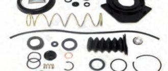
If the pedal fails, in order to avoid unreasonable disassembly of the cylinder, it is worth initially pumping the system and expelling air from there that could get in when the liquid in the tank drops below the minimum permissible level. If this does not help in principle, it is worth starting repairs. For this case, there is a repair kit for the clutch master cylinder on sale, which, depending on the make of the car, contains the main wearing parts: cuffs, return spring, rod, retaining ring, etc.
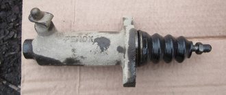
The master cylinder is located under the clutch pedal. Depending on the car model, dismantling will have to be done either from the engine compartment or from the car interior, having previously dismantled the floor covering in the driver’s area. Having removed the clutch master cylinder, we begin disassembling it, after which we need to wash all the parts. During the subsequent inspection, after disassembly, it is worth paying special attention to the body and the condition of the rod and mirror; if there are visible scuffs, this may indicate the appearance of wear in the cylinder or wear of the rod.
In general, experienced craftsmen recommend changing all the parts in the repair kit, especially the cuffs.
When repairing the clutch master cylinder, it is advisable to follow some tips:
- in the event of a malfunction and subsequent repair of the cylinder, it is not possible to completely remove the fluid from the hydraulic drive;
- When washing parts, it is highly not recommended to use kerosene, diesel fuel and gasoline for this; after this, the cuffs and other rubber products may swell; the best option for washing is brake fluid;
- Before assembly, it would be useful to lubricate all parts with brake fluid; only the spherical surface of the rod in contact with the pusher needs to be treated with grease.
Adjusting the double disc clutch
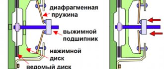
Basically, modern passenger cars are equipped with a “dry” single-disc mechanism. For the operation of most cars, this design is quite reliable and efficient. However, cargo and special vehicles, as well as sports models, require the installation of a double-disc mechanism. Similar to the single-disc design, torque is also transmitted from the flywheel to the gearbox. The only difference is that the double-disc mechanism is capable of transmitting relatively greater torque, while having a much longer service life. Structurally, the mechanisms also differ in the number of driven disks and the presence of an additional spacer between them.
The principle of operation is the same. The pressed clutch pedal moves the release bearing, which in turn acts on the levers, moving the pressure plate away from the driven one. At the same time, the release springs are also released, acting on the intermediate drive disk, which is retracted by the springs of the second friction disk. The second moves at the same pace as the first. Thanks to this, one press of the pedal exerts double force on the mechanism. The reverse procedure when engaging the coupled mechanism is performed in the same way, connecting all the disks in series. The double-disc design can be called an advanced version of the single-disc design, in which force and load are distributed evenly. It is the uniformity of distribution and increased resource that distinguish both of these versions of the “dry” type mechanism.
We will analyze the adjustment of the clutch and its other elements using the example of a MAZ truck. First of all, you should check the gap between the surfaces of the structure. To do this, adjust the distance to which the drive disk is retracted. It is also advisable to check the gap between the adjusting nut and the valve body cover. If necessary, it is worth adjusting these elements.
Next, the flywheel housing is dismantled along with the hatch cover. This is necessary for more flexible adjustment of the output of the middle drive disk. Adjustment at this stage is carried out in several steps:
- the clutch engages;
- The gearshift lever is moved to the neutral position;
- the engine flywheel rotates;
- the locknuts of the adjusting screws are unscrewed;
- 4 screws are screwed into the middle drive disk until it stops.
Then, after loosening the screws one turn, you need to continue rotating the flywheel. All elements are then secured with locknuts. At each stage of adjustment of the MAZ double-disc mechanism, it is necessary to ensure that the adjusted gap does not go astray. To do this, you have to constantly hold the screw using a suitable tool.
The next step is to measure the gap between the edge of the rear valve cover and the nut. The value should not be more than 3.3 mm. Correcting this gap is a necessary step in the entire adjustment of the MAZ double-disc mechanism.
This distance can be adjusted by loosening the corresponding lock nut. Having fixed the gap with the adjusting nut within 3.3-3.7 mm, the lock nut should be tightened. This completes the setup of the MAZ double-disc clutch mechanism.
KamAZ clutch
The leading parts of the clutch are flywheel 1, the middle drive disk 12, the pressure plate 11 and the casing 10, and the driven ones are disks 3 with dampers 2 of torsional vibrations. The force compressing the drive and driven disks is created by springs 9. Torque from the engine is transmitted to the pressure and middle drive disks through protrusions made on their outer surfaces, which fit into four longitudinal grooves on the flywheel.
Diagram 1 – Clutch (a) and clutch drive (b) of KamAZ trucks
1 – flywheel; 2 – damper; 3 – driven disks; 4 – lever mechanism; 5 – lever; 6 – bearing; 7 – coupling; 8 – ring; 9 – spring; 10 – casing; 11 – pressure disk; 12 – drive disk; 13, 16 – levers; 14 – pedal; 15, 23 – cylinders; 17, 22 – rods; 18 – pipeline; 19 – pneumatic booster; 20 – tracking device; 21 – air duct
The grooves on the flywheel allow the protrusions, and therefore the disks 11 and 12, to move relative to the flywheel when the clutch is engaged and disengaged.
A lever mechanism is installed on the middle drive disk 12 , the spring of which, when the clutch is disengaged, turns the equal-arm lever 13. In this case, the lever, resting its ends against the pressure plate 11 and the flywheel 1, sets the middle drive disk 12 at the same distance from the flywheel and the pressure plate.
The clutch release levers 5 are connected to a thrust ring 8, against which, when the clutch is disengaged, the release bearing 6 of the release clutch 7 rests, moving along the guide sleeve.
KamAZ clutch drive device
The clutch drive is hydraulic with a pneumatic booster. The drive includes (diagram 1, b) a pedal 14, a main cylinder 15, a working cylinder 23, a pneumatic amplifier 19, a follower device 20, a fork and a release clutch with a bearing, pipelines 18 and hoses for supplying working fluid from the main cylinder to the working one, as well as air duct 21 for supplying air to the pneumatic amplifier.
When the clutch is disengaged, the force from the pedal 14 through the lever 16 and the rod 17 is transmitted to the piston of the main cylinder 15, from which the working fluid under pressure through the pipeline 18 simultaneously enters the working cylinder 23 and into the housing of the follower device 20. The follower device ensures that compressed air enters the pneumatic booster 19 from air line 21. It automatically changes the air pressure in the pneumatic booster in proportion to the force on the clutch pedal. The total force created by the air pressure in the pneumatic booster 19 and the fluid pressure in the working cylinder 23 is transmitted through the rod 22 to the clutch release fork and from it to the release clutch with a release bearing.
Installing a pneumatic booster in a hydraulic drive makes it much easier to control the clutch - disengaging it and holding it in the disengaged position. If the pneumatic booster fails, the clutch is released only by fluid pressure. In this case, the force of pressing the clutch pedal increases to 600 N.
Drive master cylinder
The master cylinder of the clutch drive (diagram 2) includes a housing 3, a piston 5 with a rod 6, a sealing collar 4 and a return spring 2. Inside the housing there are cavities A and B, which are filled with working fluid. The cylinder body is closed with a protective cover 7 and a plug 1 with a threaded hole for connecting the pipeline.
Diagram 2 – Master cylinder of the clutch drive of KamAZ trucks
1 – plug; 2 – spring; 3 – body; 4 – cuff; 5 – piston; 6 – rod; 7 – cover; A, B – cavities; B – hole
When the clutch is engaged (the clutch pedal is released), the piston is in its original position under the action of spring 2. In this case, cavities A and B in the housing communicate with each other through an open hole B made in the piston.
Design and adjustment of the VAZ 2109 clutch
VAZ 2109 is the legendary “nine”. The front-wheel drive five-door hatchback was serially produced at the Volzhsky Automobile Plant from 1987 to 2004. From 2004 to the end of 2011, the VAZ 21093 modification was assembled in Zaporozhye.
Many car owners try to maintain their personal car themselves and know how to do it correctly, since they carefully study the operation of the main components and leading modules. The list of routine maintenance includes periodic adjustment of the VAZ 2109 clutch. This task is quite simple if you familiarize yourself with the operation algorithm in advance.
Nine clutch device
The clutch kit is one of the key components of the Nine transmission. This is a single-disc friction-type mechanism located between the engine and the gearbox (gearbox). The algorithm for its operation is as follows:
- Initially, the car is stationary, the engine is started, the pedal is released. The gearshift lever is in the neutral position, that is, the rotation of the input shaft is not transmitted to the secondary shaft.
- The driver is preparing to move forward. With his left foot he presses the pedal, and the mechanism disconnects the gearbox input shaft from the engine. The driver moves the lever to the first gear position, the mechanism ensures the engagement of the primary and secondary shafts of the gearbox. The car is stationary because the engine is disconnected from the transmission input shaft.
- The driver smoothly but decisively releases the pedal. The engine is connected to the input shaft, the task of which is to transmit power to the drive wheels through the secondary shaft, then the car will start moving.
- Switching from first gear to second, from second to third, and so on occurs in the same way.
The VAZ 2109 clutch design is such that when the pedal is released, the driven disk is clamped by springs between the flywheel and the pressure plate. In this case, power is transferred to both gearbox shafts and the drive wheels.
When you press the pedal, the VAZ 2109 clutch fork rotates through a special rod and presses on the levers that retract the pressure plate. The VAZ 2109 clutch driven disc is disconnected and power transmission stops. The mechanism casing is connected to the pressure plate by three pairs of elastic plates.
The unit is driven by a cable, its lower tip is fixed with nuts in a bracket on the engine crankcase.
The clutch cable is connected to the clutch release fork lever.
Typical VAZ 2109 clutch malfunctions
The clutch is one of the relatively reliable units of the VAZ 2109. With normal operation and periodic adjustment, it lasts for years. The estimated resource of the unit exceeds 100 thousand km. And if the clutch pedal fails, this is a rare case. The list of typical faults includes:
| Type of problem. | What is expressed? | What is the reason. |
| The clutch drives. | Pressing the pedal all the way does not ensure complete disconnection of the shaft from the gearbox, and the engine is not disconnected from the gearbox. Pressing the pedal when the unit is faulty leads to the fact that the pressure bearing does not act strongly enough on the damper spring, and the engine flywheel continues to partially transmit torque to the gearbox shaft. | The reason for this is often poor adjustment of the VAZ 2109 clutch cable or failure of the drive disk. |
| The clutch is slipping. | When the pedal is fully released, the gearbox input shaft remains loosely pressed against the engine flywheel and slips, that is, slippage occurs. The torque is only partially transmitted to the drive wheels and sliding of the contact surfaces occurs. This effect is clearly manifested when a loaded car is moving uphill: the driver accelerates, the speed increases, but the car almost does not accelerate, the clutch of the VAZ 2109 slips. | In this case, the drive is most often poorly adjusted, the clutch cable gets stuck, the driven disc is worn out or oily, which is why the clutch slips. |
| Noise when switching off transmission. | When you press the pedal, a distinct rustling or rustling sound is heard. | This quiet sound may indicate a possible release bearing failure. Continuing to operate the car in this condition can lead to troubles: if it jams, the VAZ 2109 clutch basket will inevitably quickly fail. Change the bearing at the first sign of a malfunction, otherwise serious repairs to the clutch, including replacement of the basket, are inevitable. |
Malfunctions and repairs of the clutch master cylinder
If we talk about the GCS, like any other device, this element can also fail. Although the clutch master cylinder is simple in design and reliable, over time individual elements wear out due to constant loads, especially if the car is operated in the city.
As a rule, seals and rubber parts are the first to fail. To put it simply, such sealing elements should be understood as boots that are put on the rod to protect the cylinder from dirt and small abrasives, as well as sealing collars that do not allow the working fluid to leak out.
Another element that can cause problems with the cylinder head is the spring in the cylinder. The spring of the clutch master cylinder constantly experiences loads during vehicle operation, and it is also affected by the brake fluid, which in this case performs the working function. When the metal becomes more brittle, the spring may simply burst.
One way or another, if there is a problem, the cylinder needs to be replaced. At the same time, in a number of cases it is also possible to get by with repairing the main central heating system rather than replacing it. Taking into account the relatively high cost of the part for many cars, this method is optimal. For these purposes, you need to purchase a clutch cylinder repair kit, which includes the necessary spare parts.
This approach usually allows you to sort out the device and completely restore its functionality. The main thing is that the repair kit is of high quality, and that the repair of the clutch master cylinder itself is carried out by experienced specialists.
Which clutch kits are better: opinions of car owners
“I had a German Sach kit consisting of a basket and a disc. I drove about 230 thousand km with it, during which the forks and release bearings were changed twice. At the moment I am using a Turkish product from Kraft. Comparing it in the store with the “German”, I did not notice any design differences. Moreover, the Turkish kit is cheaper. So is it worth overpaying?
“The factory clutch on my VAZ-2112 lasted 67 thousand km. During this time, the friction linings were worn out almost completely. Today I finally changed the kit along with the basket and release plate. For a long time I was choosing between products from Valeo, Sachs and VIS, but in the end I settled on the option from Luk. Namely, we chose Luk Priora, which is included in the basic configuration of this car. I was mainly guided by positive reviews from experienced drivers regarding stable torque.
It is noteworthy that the first batches of this product, judging by the description, contained copper rivets, and later ones were silver and without inscriptions. The clutch disc looks high quality and neatly made, and the basket also inspires confidence with its appearance.
The release disc has a plastic seating ring, and this fact was alarming. Moreover, this clip turned out to be skewed! Only later did specialists explain to me that such a distortion is considered normal. The disk will self-center and will eventually move into the desired position. However, mistrust of plastic still remains, so let’s watch.
As for the first impressions of operation, it is worth noting a softer pedal press. It seems that its stroke has increased, although in fact it remains at the level of the brake pedal. The mileage with this kit is still low. Let's see what will happen next".
“I installed Krafttech, VIS and Sachs kits. The latter still stands today, there are no complaints about this product. On the contrary, I am very pleased with this set. When I press the clutch, I don't feel any stiffness. There is no discomfort when driving through traffic jams.”
“I’ll write my opinion about the kit from Valeo and about the manufacturer itself. I have five years of experience in the sales of spare parts, so I know very well the opinions of customers regarding this or that brand. Regarding Valeo, I can say that this company maintains a high quality standard. The cost of its products is also high. According to these parameters, this French manufacturer has overtaken manufacturers from the Czech Republic, Poland and, of course, China. In general, buyers positively evaluate the qualities of Valeo kits, such as soft operation and resistance to high operating temperatures. For many car owners, these are very important factors.
Products from Valeo can withstand a mileage of 100 thousand km, provided that they are original French products. I personally sold two types of Valeo clutches, which differed only in quality and cost. I will list the main features of French products from my point of view:
- Original products are produced exclusively in France.
- The clutch disc, its basket and release bearing are sold in individual packages.
- The kit always includes branded lubricant and a syringe. I have never seen anything like this in anyone else.
- Instructions for installing the kit are also included.
- The metal has a matte finish. The same Chinese, on the contrary, make the coating of their products glossy for the sake of attractiveness.
- Manufacturer's stamps are applied to both original and non-original products. The difference may be visible in copies that appear blurrier.”
“I have a rather old VAZ V8, produced in 2000. Recently the clutch basket failed. I decided to take on the repairs myself and also change the clutch disc along with the basket, despite the still working condition of the old one. I collected as much information as possible about various manufacturers of spare parts, consulted with friends, and in the end my choice fell on a kit from Vis. The basket and disk included in this kit cost me a maximum of 2,000 rubles (this price is considered average). I drove about 8000 km on this kit without any complaints. The mechanism works smoothly, does not lead or slip. In general, I’m happy so far.”
MAZ clutch and part device
The MAZ clutch is a double-disc friction type device. It has springs that are located peripherally. The MAZ clutch device also includes discs. The elements are made of durable materials. The MAZ clutch is installed in a crankcase made of strong cast iron. The leading parts of the mechanism are the MAZ clutch disc (middle and pressure) and the MAZ flywheel. AvtoResurs LLC offers a closer look in a number of articles on how to adjust the MAZ clutch and repair the part. However, today we will tell you what the MAZ clutch device consists of and how the MAZ clutch drive works.
1. The MAZ clutch has a complex structure
Let's look at the Minsk Automobile Plant truck model 5335. Let's carefully study the MAZ clutch design. So, the mechanism includes a huge number of elements, for example:
- Release lever and springs;
- MAZ clutch fork, rings, rod;
- Nut, plates, MAZ clutches;
- Fork shaft lever, pin, MAZ clutch cover;
- Gaskets, MAZ clutch disc, flywheel and hubs.
These components are the main ones in the design of MAZ spare parts. Also, all mechanisms are strong and resistant to heavy loads. Therefore, the MAZ clutch, as well as the MAZ clutch drive, last a long time and rarely fail. Cast iron is mainly used for the manufacture of elements from the MAZ clutch device. Let's take a closer look at each part of the part being studied. The MAZ clutch disc (pressure and drive) is cast from durable cast iron.
Has spikes that attach to the truck's flywheel. Thus, the MAZ clutch is a very strong connection, which makes it easy to move the MAZ clutch disc. Also in this case, torque is transmitted to an element such as the MAZ clutch disc from the flywheel. A frictional force arises. The MAZ clutch has several friction attachments that contain the MAZ clutch disc. Therefore, during the operation of the elements, a frictional force occurs.
That is, torque is transmitted from the surface of the friction linings, discs and flywheel to the MAZ gearbox. Note that the MAZ clutch drive of a modern truck does not include discs. 2. MAZ clutch is reliable and strong
Features of the MAZ double-disc clutch
A classic of dry-type clutches produced in Minsk is the MAZ double-disc clutch, which is mounted on a MAZ vehicle. The springs of this unit are located peripherally and this is its main difference from other devices. The quality indicators of the springs may have different indicators, but this does not change the operation of the clutch.
The direct task of a double-disc clutch is to transmit high-quality torque; for this, the middle and pressure drive disks have two pairs of remote contacts located on the plane of the spring device. Contact-directed tides work with the flyshaft, thereby transporting the entire assembly along the axis in the absence of any obstacles. These are the basic principles of operation of a MAZ double-disc clutch.
Source
Applicability:
MAZ-104; MAZ-105; MAZ-152; MAZ-103; MAZ-104S; MAZ-107; MAZ-543202; MAZ-551605; MAZ-6303A3, 6303A5; MAZ-5336; MAZ-6303; MAZ-5337; MAZ-5516; MAZ-650119; MAZ-555142; MAZ-533731; MAZ-5440B9, 6430B9; MAZ-437130 (Zubrenok); MAZ-642505, 642508; MAZ-5440E9; MAZ-544069; MAZ-6422, 5432; MAZ-437040 (Zubrenok); MAZ-6422; MAZ-5551; MAZ-5432; MAZ-5516A5; MAZ-6430A8(5440A8, 440A5); MAZ-631236; MAZ-651705; MAZ-630333; MAZ-437041 (Zubrenok); MAZ-650108; MAZ-6516V8-520 (6516V8-540).
Source
Old style MAZ clutch valve
3.3.3 Mechanical clutch release drive with pneumatic booster
On Ural and MAZ vehicles with YaMZ-236M2 and YaMZ-238M2 engines with double-disc clutches, a mechanical drive with a pneumatic booster is installed. On Ural vehicles, diaphragm single-plate clutches YaMZ-182 or YaMZ-183 of the pull-out type with a hydraulic drive and pneumatic hydraulic booster can be installed.
When the clutch pedal 16 (Figure 3.12) is acted upon, the force through the lever 11 and the rod parts 9 is transmitted to the rod of the pneumatic valve 1, opening its valve. Air pressure from the car's pneumatic system through hose 19 enters cylinder 20, which additionally acts on lever 18.
1 – pneumatic valve; 2 – lock nut; 3 – adjusting bolt; 4 – thrust with compensator; 5 – bracket; 6.22 – brake valve levers; 7 – clutch drive lever; 8, 19 – hoses; 9 – clutch pedal rod; 10 – brake pedal thrust; 11 – clutch pedal shaft lever; 12 – clutch pedal shaft; 13 – clutch pedal travel limiter; 14 – brake pedal release spring; 15 – clutch pedal spring; 16 – clutch pedal; 17 – brake pedal; 18 – clutch fork shaft lever; 20 – pneumatic cylinder; 21 – brake valve rod; L – full travel of the clutch pedal; L1 – full travel of the brake pedal
Figure 3.12 – Clutch release drive for Ural vehicles
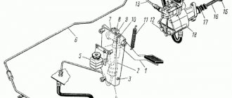
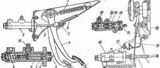
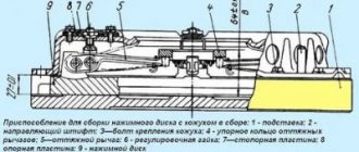
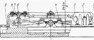
The clutch release drive with the pneumatic booster of MAZ vehicles is shown in Figure 3.13. Valve 16 with rod 9 assembly is connected to the mechanical drive in series, and the working cylinder 13 of the amplifier is installed directly on the power unit parallel to the mechanical drive. Double-arm lever 11 is connected to the valve stem and the working cylinder rod.
1,6,9 – thrust; 2 – pedal; 3 – finger; 4,7,11 – levers; 5 – tension spring; 8,12,15 – forks; 10 – retaining ring; 13 – cylinder; 14 – cylinder rod; 16 – valve; A – gap
Figure 3.13 – Clutch release drive
Hole A of the clutch booster valve (Figure 3.14) is connected by a hose to the brake valve and is therefore under air pressure from the pneumatic system, hole B is with the above-piston space of the booster cylinder (Figure 3.14a), and hole B (Figure 3.14) in the valve rod is with atmosphere .
2,4,11 – nuts; 3 – traction; 5 – front cover; 6,8,14 – sealing rings; 7 – valve body; 9 – rod; 10.15 – retaining rings; 13 – back cover; 16.18 – spring; 17 – channel for supplying compressed air to the valve; B – channel for supplying compressed air to the cylinder; B – outlet
Figure 3.14 – Clutch release booster valve
When the driver presses the clutch pedal through the lever system, rod 9 (Figure 3.13) together with the amplifier valve body moves to the right, selecting gap A between the retaining ring 10 and the valve body cover. In this case, valve 17 (Figure 3.14) rests against valve stem 9 and is torn away from the seat. Air under pressure from cavity A rushes into cavity B and then into the above-piston space of the amplifier cylinder. Under the influence of air pressure, the cylinder piston moves to the left, helping to rotate the double-arm lever counterclockwise, which ensures that less force is used on the pedal to disengage the clutch. When the force is removed from the pedal, the valve is pressed against its seat by spring 17, and the air from the cylinder escapes into the atmosphere through outlet B.
1 – fork; 2 – nut; 3 – rod; 4 – cotter pin; 5 – tightening tape; 6 – piston; 7 – cover; 8 – sealing ring; 9 – bracket; 10 – cuff; 11 – retaining ring; 12 – body; 13 – ring; 14 – cover; 15 – filter cap
Figure 3.14,a – Clutch release amplifier cylinder
Source