Not available:
| № | Part code | Name | Part Information |
| 5551-1602741 | Booster valve | Quantity for MAZ-5337 2) MAZ-53371 3) MAZ-54323 4) MAZ-5516 5) MAZ-5551 6) MAZ-64229 1 Model 5551 Clutch group Subgroup Clutch control pedal and drive Serial part number 741 | Not available |
| 250615 | Nut M12x1.25-6N | Quantity for MAZ-5337 2) MAZ-53371 3) MAZ-54323 4) MAZ-5516 5) MAZ-5551 6) MAZ-64229 8 Uncoated coating | Not available |
| 201418 | Bolt M6-6gх16 | Quantity for MAZ-5337 2) MAZ-53371 3) MAZ-54323 4) MAZ-5516 5) MAZ-5551 6) MAZ-64229 8 Uncoated coating | Not available |
| 252134 | Washer 6T | Quantity for MAZ-5337 2) MAZ-53371 3) MAZ-54323 4) MAZ-5516 5) MAZ-5551 6) MAZ-64229 1 Uncoated coating | Not available |
| 5336-1602752 | Rear cover | Quantity for MAZ-5337 2) MAZ-53371 3) MAZ-54323 4) MAZ-5516 5) MAZ-5551 6) MAZ-64229 1 Model 5336 Clutch group Subgroup Clutch control pedal and drive Serial part number 752 | Not available |
| 012-016-25-2-3 | Ring | Quantity for MAZ-5337 2) MAZ-53371 3) MAZ-54323 4) MAZ-5516 5) MAZ-5551 6) MAZ-64229 1 | Not available |
| 64221-1602748 | Stock | Quantity for MAZ-5337 2) MAZ-53371 3) MAZ-54323 4) MAZ-5516 5) MAZ-5551 6) MAZ-64229 2 Model 64221 Clutch group Subgroup Clutch control pedal and drive Serial part number 748 | Not available |
| 025-031-36-2-3 | Ring | Quantity for MAZ-5337 2) MAZ-53371 3) MAZ-54323 4) MAZ-5516 5) MAZ-5551 6) MAZ-64229 1 | Not available |
| 400337 | Retaining ring | Quantity for MAZ-5337 2) MAZ-53371 3) MAZ-54323 4) MAZ-5516 5) MAZ-5551 6) MAZ-64229 1 Uncoated coating | Not available |
| 500A-1602746 | Spring | Quantity for MAZ-5337 2) MAZ-53371 3) MAZ-54323 4) MAZ-5516 5) MAZ-5551 6) MAZ-64229 1 Model 500A Clutch group Subgroup Clutch control pedal and drive Serial part number 746 | Not available |
| 5336-1602742-10 | Valve body | Quantity for MAZ-5337 2) MAZ-53371 3) MAZ-54323 4) MAZ-5516 5) MAZ-5551 6) MAZ-64229 1 Model 5336 Group Clutch Subgroup Clutch control pedal and drive Serial number of part 742 Additionally Not interchangeable with a part released earlier under the same number | Not available |
| 500-3515230-10 | Clutch booster valve | Quantity for MAZ-5337 2) MAZ-53371 3) MAZ-54323 4) MAZ-5516 5) MAZ-5551 6) MAZ-64229 1 Model 500 Group Brakes Subgroup Pressure drop limiting valve (control and safety hardware) Serial number of part 230 Additionally Not interchangeable with a part released earlier under the same number | Not available |
| 842-8524120 | Spring | Quantity for MAZ-5337 2) MAZ-53371 3) MAZ-54323 4) MAZ-5516 5) MAZ-5551 6) MAZ-64229 1 Model 842 Group Platform Subgroup 8524 Serial part number 120 | Not available |
| 5336-1602753-10 | Front cover | Quantity for MAZ-5337 2) MAZ-53371 3) MAZ-54323 4) MAZ-5516 5) MAZ-5551 6) MAZ-64229 1 Model 5336 Group Clutch Subgroup Clutch control pedal and drive Serial number of part 753 Additionally Not interchangeable with a part released earlier under the same number | Not available |
3.3.3 Mechanical clutch release drive with pneumatic booster
3.3.3 Mechanical clutch release drive with pneumatic booster
On Ural and MAZ vehicles with YaMZ-236M2 and YaMZ-238M2 engines with double-disc clutches, a mechanical drive with a pneumatic booster is installed. On Ural vehicles, diaphragm single-plate clutches YaMZ-182 or YaMZ-183 of the pull-out type with a hydraulic drive and pneumatic hydraulic booster can be installed.
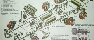
When the clutch pedal 16 (Figure 3.12) is acted upon, the force through the lever 11 and the rod parts 9 is transmitted to the rod of the pneumatic valve 1, opening its valve. Air pressure from the car's pneumatic system through hose 19 enters cylinder 20, which additionally acts on lever 18.
1 – pneumatic valve; 2 – lock nut; 3 – adjusting bolt; 4 – thrust with compensator; 5 – bracket; 6.22 – brake valve levers; 7 – clutch drive lever; 8, 19 – hoses; 9 – clutch pedal rod; 10 – brake pedal thrust; 11 – clutch pedal shaft lever; 12 – clutch pedal shaft; 13 – clutch pedal travel limiter; 14 – brake pedal release spring; 15 – clutch pedal spring; 16 – clutch pedal; 17 – brake pedal; 18 – clutch fork shaft lever; 20 – pneumatic cylinder; 21 – brake valve rod; L – full travel of the clutch pedal; L1 – full travel of the brake pedal
Figure 3.12 – Clutch release drive for Ural vehicles
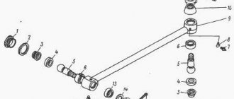
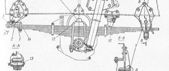
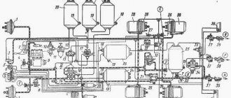
The clutch release drive with the pneumatic booster of MAZ vehicles is shown in Figure 3.13. Valve 16 with rod 9 assembly is connected to the mechanical drive in series, and the working cylinder 13 of the amplifier is installed directly on the power unit parallel to the mechanical drive. Double-arm lever 11 is connected to the valve stem and the working cylinder rod.
1,6,9 – thrust; 2 – pedal; 3 – finger; 4,7,11 – levers; 5 – tension spring; 8,12,15 – forks; 10 – retaining ring; 13 – cylinder; 14 – cylinder rod; 16 – valve; A – gap
Figure 3.13 – Clutch release drive
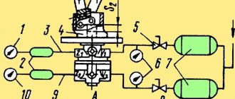
Hole A of the clutch booster valve (Figure 3.14) is connected by a hose to the brake valve and is therefore under air pressure from the pneumatic system, hole B is with the above-piston space of the booster cylinder (Figure 3.14a), and hole B (Figure 3.14) in the valve rod is with atmosphere .
2,4,11 – nuts; 3 – traction; 5 – front cover; 6,8,14 – sealing rings; 7 – valve body; 9 – rod; 10.15 – retaining rings; 13 – back cover; 16.18 – spring; 17 – channel for supplying compressed air to the valve; B – channel for supplying compressed air to the cylinder; B – outlet
Figure 3.14 – Clutch release booster valve
When the driver presses the clutch pedal through the lever system, rod 9 (Figure 3.13) together with the amplifier valve body moves to the right, selecting gap A between the retaining ring 10 and the valve body cover. In this case, valve 17 (Figure 3.14) rests against valve stem 9 and is torn away from the seat. Air under pressure from cavity A rushes into cavity B and then into the above-piston space of the amplifier cylinder. Under the influence of air pressure, the cylinder piston moves to the left, helping to rotate the double-arm lever counterclockwise, which ensures that less force is used on the pedal to disengage the clutch. When the force is removed from the pedal, the valve is pressed against its seat by spring 17, and the air from the cylinder escapes into the atmosphere through outlet B.
1 – fork; 2 – nut; 3 – rod; 4 – cotter pin; 5 – tightening tape; 6 – piston; 7 – cover; 8 – sealing ring; 9 – bracket; 10 – cuff; 11 – retaining ring; 12 – body; 13 – ring; 14 – cover; 15 – filter cap
Figure 3.14,a – Clutch release amplifier cylinder
Issues of selection, replacement and maintenance of the MAZ clutch valve
KUS is a pneumatic unit, which is additionally subjected to mechanical loads and negative environmental factors. All this leads to gradual wear of the valve and can cause various malfunctions - damage to the valve, air leaks through the seals, deformation of the rod and rod, damage to the body, “sagging” of the springs, etc. If signs of deterioration in clutch performance appear, it is necessary to check the valve, and if a malfunction is detected, repair or completely replace it.
For replacement, you must take a valve of the same type and model that was installed on the car previously, or it is recommended as an acceptable analogue by the manufacturer. Here you need to take into account that valves of different types have different characteristics and dimensions, so a “non-original” part may not only not fit into place, but also not ensure normal operation of the clutch drive.
When purchasing a valve, you also need to take into account its equipment; if necessary, you may need to purchase additional hoses, forks and fasteners. To avoid unnecessary costs and loss of time, you must immediately check the condition of the parts in the drive, fasteners and hoses.
Replacing the valve must be carried out in accordance with the car repair instructions, but usually this operation comes down to simply dismantling the old part and installing a new one, while bleeding the air from the pneumatic system. Then you should definitely adjust the valve using the nut on its stem - the distance between it and the back cover of the KUS body should be 3.5 ± 0.2 mm. To set the gap, you need to loosen the lock nut, install the adjusting nut at the specified distance from the housing cover, and tighten the lock nut. Subsequently, all routine maintenance of the valve is reduced to its external inspection and adjustment of the specified gap.
Clutch valve MAZ 5336-1602738-10, 63031-1602738, 5551-1602738-10, 54323-1602738
As you know, the MAZ clutch system in trucks is one of the complex components, which makes the unit itself very expensive in any sales market. In the MAZ catalog on the company's official website, you can easily find MAZ spare parts that are provided by. Among our numerous products you can find clutch valves at the lowest market prices, which will pleasantly surprise you and at the same time please you.
Why is this clutch valve still needed and what role does it play for a MAZ car? It is very easy to find the answer to this question, even without delving too deeply into the design of MAZ trucks.
The valve itself acts as a kind of “switch”, which in turn controls the pneumatic drive cylinder, which is responsible for disengaging the clutch at the right time. If you look at the clutch valve, you won’t be able to see anything special - a simple valve that is also installed on simple passenger cars with a manual transmission, only, of course, it is larger in size. But if we consider the clutch valve proposed by our company, which is produced at Baranovichi Automotive Aggregate Plant OJSC, then we can note that in terms of performance characteristics this unit has no resemblance to its passenger “brother”. For example, the working pressure, which is nominal according to the official catalog, is 0.6/6 MPa/kgf/cm2. Of course, such data can only be used in the clutch system for a MAZ car. That is why you need to choose a clutch valve according to the catalog from BAAZ, which will warn you against unexpected counterfeits, which, by the way, can be found among unofficial representatives of BAAZ.
As for the installation/disassembly of the MAZ clutch valve, it is worth noting the fact that, first of all, you need to contact specialists, since this operation should be performed only by highly qualified service station specialists. If in your city, for example, there is no car service center to carry out work on the MAZ clutch system, then you need to contact the nearest place. Remember that work performed by specialists in the field of auto repair of trucks provides at least a guarantee that the clutch valve is installed correctly. And in turn, correct installation of this unit makes driving the MAZ as safe as possible.
It should be noted that the MAZ clutch valve has different rod lengths. Accordingly, in the MAZ numbering there are different catalog numbers of the clutch valve, which correspond to the required spare part.
So they distinguish:
- clutch valve MAZ 5336-1602738-10, with a rod length of 145 mm;
- clutch valve MAZ 63031-1602738, with a rod length of 235 mm;
- clutch valve MAZ 5551-1602738-10, with a rod length of 325 mm;
- clutch valve MAZ 54323-1602738, with a rod length of 80 mm.
In our MAZ catalog, you can also find a clutch valve without hoses under catalog number 5335-1602741.
OJSC Baranovichi Automotive Aggregate Plant has been cooperating with our company for a long time. This cooperation began several years ago, when the need arose to supply MAZ spare parts throughout the CIS. Our company today is the main dealer of BAAZ, which, in turn, through our representative office, can offer the buyer a huge selection of spare parts and units not only for trucks, but also for the bus fleet of any city.
Cooperation between our company and BAAZ is carried out only in a positive manner and with understanding on both sides of entrepreneurial interest. By presenting the products of Baranovichi Automotive Aggregate Plant OJSC, we give customers the opportunity to purchase MAZ spare parts not only at ultra-low prices, but also to provide their working equipment with only high-quality products that meet all international standards.
In the official catalogs of our website you can easily find the necessary MAZ spare parts, which all have a BAAZ production certificate, which confirms only original spare parts and high quality. Shopping with us is fast, simple and reliable!
You can also follow our company’s blog on social networks twitter, facebook, contact, google+.
General structure and principle of operation of MAZ clutch valves
All MAZ vehicles use the KUS that is fundamentally the same in design. The basis of the design is a cylindrical body assembled from three cast parts - the body itself and two end covers. The covers are usually of a flange design, they are attached to the body with screws, and gaskets are always used for sealing. A rod of increased length is rigidly installed in the front cover of the housing, at the end of which there is a fork for connection to the intermediate double-arm clutch drive lever.
The body is divided into two cavities, each of which has threaded channels for connecting hoses. In the front cavity there is a valve, in its normal position pressed against its seat by a spring (its role is played by a collar between the cavities). The channel in the front cavity is a supply channel - through it, compressed air is supplied to the valve from the corresponding receiver of the car's pneumatic system.
In the rear cavity of the housing there is a hollow rod extending from the rear cover and carrying a fork for connection to the double-arm lever of the clutch fork shaft. The rod has a cavity communicating with the atmosphere. There is a thread cut on the rod on which the adjusting nut is located along with its lock nut. The channel in the rear cavity is an outlet; a hose is attached to it, providing compressed air to the amplifier cylinder, as well as exhausting air from the cylinder back to the CUS when the pedal is released.
The operation of the KUS and the entire PVS with pneumatic booster is quite simple. When the clutch pedal is released, the valve is closed, so the PVA is inactive - the clutch is engaged. When you press the pedal, the KUS, together with the other components of the PVA, moves to select the gap between the adjusting nut on the rod and the rear housing cover. In this case, the rod rests against the valve and lifts it - as a result, air from the front cavity of the valve flows into the rear and through the hose enters the clutch booster cylinder. Under the influence of the force of compressed air, the cylinder piston moves and rotates the clutch fork shaft - it lifts the pressure plate and disengages the clutch. When the pedal is released, the above processes occur in the reverse order, the valve closes and the air from the amplifier cylinder is vented into the atmosphere through the rear cavity of the KUS and the cavity in its rod, the force is removed from the fork and the clutch is engaged again.