Design and principles of operation
The design of the coupling mechanism includes such elements as:
- flywheel;
- hydraulic power steering;
- overlays;
- a spring device that presses the disk against the flywheel housing;
- clutch release fork, clutch release drive;
- push-type coupling;
- coupling pedal shaft;
- pressure disk;
- double-disc or single-disc petal device;
- release bearing;
- protective casing;
- transmission drive shaft.
- When the driver presses the pedal, the shaft begins to rotate.
- A gap forms between the fork and the push-type coupling.
- The clutch, together with the bearing, begins to move, causing the bearing to exert pressure on the inner ring of the handle.
- The handle moves the pressure plate away from the driven disc.
- The spring mechanism is compressed, causing the disk to move towards the flywheel of the power unit.
- The splines of the driven disk move to the splines of the gearbox input shaft.
How the repair is carried out
Main malfunctions and ways to eliminate them:
- The clutch mechanism is slipping. This may be due to the lack of free play of the pedal, jamming of the piston part, wear of the friction linings. In this case, it is recommended to adjust the free play of the pedal, clean all cylindrical elements and valves with kerosene, and replace damaged linings and cylinders.
- The clutch moves or does not disengage completely. Such a malfunction can be caused by an incorrectly adjusted length of the cylinder rod, insufficient air pressure in the pneumatic system, a leak in the piston seal, or failure of the pull-out levers. The rod length should be re-adjusted, the pneumatic system should be inspected and, if necessary, leaks should be eliminated, the cylinders should be flushed, and all damaged and worn parts should be replaced.
- The pedal does not return to its original position. It is recommended to adjust the gap between the back cover and the lock ring, replace worn valves, move the spring mechanism holder closer to the rod, eliminate defects in the rods, clean and lubricate the cylindrical elements of the system.
How to replace
Replacing the clutch is carried out in several stages:
How to remove
In order to dismantle the coupling mechanism, you must perform the following steps:
- Place the vehicle on a special platform or inspection hole.
- Remove the battery.
- Remove the air filter element.
- Remove the engine splash guards, which are located in the lower and side parts of the power unit compartment.
- Remove the front suspension cross member.
- Remove the front drive wheels.
- Drain the oil fluid.
- Disconnect the speed sensor using a screwdriver.
- Remove the reverse switch.
- Remove the engine harness holder.
- Unscrew the mounting bolts and remove the starter housing.
- Disconnect the engine mounts from the gearbox bracket.
- Move the clutch back.
- Remove the input shaft of the mechanism.
- Unscrew the mounting bolts from the coupling mechanism housing. The bolts are unscrewed one by one, in 2-3 steps.
- Remove the pressure plate along with the casing.
Assembly
Clutch mechanism assembly steps:
- Assemble the driven disk. To do this, it is necessary to attach friction linings to a plastic spring device.
- Assemble the pressure plate. You need to lubricate the rollers with a special liquid, place them in the hole of the pull handles, insert the lever into the groove that is located on the pressure-type disk, and install the finger. Attach the support forks to the levers and secure them with cotter pins.
- Assemble the pressure disk with the casing. This must be done under a press that can compress the springs and screw the bolts into the support forks. A driven type disk is placed under the press, and a pressure disk is placed on top. Heat-insulating washers and the spring mechanisms themselves are installed on special protrusions. Press the casing using a press and tighten the mounting bolts.
- Installing discs into the clutch housing.
Procedure for installing the clutch:
- Install the driven disc so that the extended end of the hub faces the flywheel.
- Install the drive disk element with rods.
- Install a second driven disk with the elongated end of the hub pointing towards the gearbox.
- Install the pressure plate.
- Attach the cut adjusting rings to the structure.
- Install the stop bars and secure them with the casing.
- Install the clutch mechanism on the flywheel, check the gap between the thrust rings and washers by engaging the clutch mechanism.
How to install disks
Many drivers are interested in how the clutch disc is installed on a MAZ.
In order to install clutch discs, you must:
- Disconnect the driveshaft.
- Remove the brake drum and pads from the wheels.
- Using a wrench, unscrew the fasteners from the axle shafts and pull them out.
- Unscrew the screws that adjust the position of the propeller shaft flange and gearbox.
- Disconnect the contacts of the sensor wires, which is responsible for turning on the reverse lights.
- Using a 12mm wrench, unscrew the mounting screws from the clutch mechanism protective cover.
- Remove the casing.
- Using a small crowbar, pry the gearbox housing away from the power unit.
- Remove the basket from the flywheel.
- Secure the flywheel.
- Remove damaged disk elements and replace them with new ones. The driven clutch disc should be directed towards the gearbox, and the pressure disc should be placed so that the hub is directed towards the engine.
- Reassemble the coupling mechanism by performing all steps in reverse order.
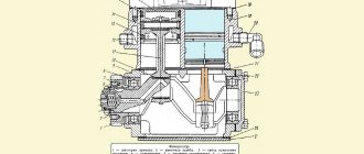
Assembling a MAZ car gearbox
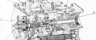
The gearbox is assembled in three stages: assembly of the drive shaft and drive shaft bearing cap, intermediate and driven shafts, gearbox top cover, remote gear shift mechanism, oil pump, general gearbox assembly and testing
The drive shaft and drive shaft bearing cap are assembled in the following sequence:
- install the drive shaft (see Fig. 1) with a toothed rim on the stand and press the rear ball bearing onto the shaft neck until it stops, having previously installed a retaining ring in the groove of the outer race;
- screw a ring nut onto the threaded neck of the shaft and tighten it until it stops. The edge of the nut is pushed into the groove of the shaft;
— install the cap 3 of the drive shaft bearing with the socket under the oil seal upwards and press the oil seal into the socket until it stops, having previously lubricated the outer surface of the oil seal with nitro enamel.
The intermediate and driven shafts are wiped before assembly, and the mating surfaces are lubricated with oil.
The intermediate shaft is assembled in the following order:
— install shaft 17 (see Fig. 1) with a gear rim on the table of a hydraulic press, press a key into the groove of the shaft and press gear 19 of the second gear onto the shaft until it stops against the gear rim of the shaft. The gear hub 19 should face away from the ring gear;
- put the spacer sleeve of the gears of the second and third gears on the shaft, press a segment key into the groove of the shaft and press gear 21 of the third gear all the way with the short hub towards the spacer sleeve;
— press a key into the shaft groove and press gear 22 of the fifth gear all the way with the short hub towards gear 21 of the third gear;
— press a key into the shaft groove and press the power take-off gear 23 with the long hub from the fifth gear gear 22 until it stops;
— press a key into the shaft groove and press gear 24 all the way with the long hub towards gear 23 of the power take-off;
— install the front thrust ring into the shaft groove, press the front roller bearing onto the shaft until it stops, and install the bearing thrust ring into the shaft groove.
The driven shaft is assembled in the following sequence:
— install shaft 14 (see Fig. 1) with the threaded end down;
- install the thrust washer on the shaft until it stops at the end of the spline surface and gear 11 of the second gear with the ring gear from the thrust washer. The gear on the shaft should rotate easily without jamming;
— press the keys into the grooves of the shaft and press the spacer sleeve of the gears of the second and third gears onto the shaft until it stops, with the large end facing the gear II of the second gear;
— install the synchronizer 10 of the second and third gears assembled with the carriage with a short hub to the gear 11 of the second gear on the splines of the spacer sleeve;
— press the bushing of gear 9 of the third gear onto the shaft until it stops in the spacer sleeve, aligning the cutout in the bushing with the key of the spacer sleeve, and install gear 9 on the bushing with a spur ring towards synchronizer 10. The gear on the shaft should rotate easily without jamming;
— check the longitudinal movement of the synchronizer 10 cone ring race, which should be within 3-5 mm. The engagement of the synchronizer carriage teeth with the gear teeth should be easy, without jamming;
— press the bushing of gear 8 of the fifth gear onto the shaft until it stops with the collar towards gear 9 of the third gear and, at the same time aligning the pin of the bushing with the groove of the shaft, install gear 8 on the bushing with a spur ring away from the collar of the bushing.
The gear should rotate on the shaft easily, without jamming;
— install the thrust washer of fifth gear gear 8, rotating it until the protrusions of the washer align with the shaft splines, and press in the locking key.
The gap between the fifth gear bushing and the thrust washer should be in the range of 0.02-0.1 mm, which is ensured by selecting the thickness of the thrust washer before installing the fifth gear.
Thrust washers are made in three thicknesses: 7-0.58, 7.15-0.58 and 7.3-0.58 mm;
— install synchronizer 5 of the fourth and fifth gears on the splines of the driven shaft 14 with the spur ring of the carriage of smaller diameter towards the fifth gear gear;
— press the front roller bearing onto the front journal of the shaft until it stops and install the thrust spring ring into the groove on the front journal;
- press the oil seal into the hole in the cover 15 of the driven shaft flush with the inner end of the hole. Before pressing the oil seal, the seating surface of the hole in the cover is lubricated with nitro enamel.
The upper cover of the gearbox is assembled in the following sequence:
— insert the spring 19 and the locking ball 18 into the cover socket 1, insert the rod 21 into the holes of the cover while simultaneously installing the reverse gear head 11 and fork 3 onto the rod.
When installing the rod, use a mandrel (Fig. 3). Align the threaded holes of the head and fork with the holes in the rod and secure them with a locking screw, which is secured with a cotter pin;
— install rod 5 of the third and fourth gear shift fork into cover 1 (Fig. 2) and at the same time install fork 8 onto the rod.
Align the threaded hole in the fork with the hole in the rod and secure the fork with a locking screw 9, which is secured with a cotter wire;
— insert two balls 7 of the gear shift rod lock into the channels of the cover under the reverse fork rod 21 and under the third and fourth shift fork rod 5;
— set rods 21 and 5 to the neutral position;
— insert the rod lock pin into the hole of the rod, which should move freely in the hole, and the assembled rod with head 1 and fork 4 installed on it for shifting the first and second gears is inserted into the cover.
Align the threaded holes of the head and fork with the holes in the rods and install a locking screw in them, which is secured with a cotter wire;
— insert plugs 10 into the holes in the cover under the rods.
— The plugs are installed on nitro enamel;
— install the reverse gear lever 15 on the cover and secure it with axle 14, onto the threaded end of which a nut is screwed
— insert the fuse spring into glass 13 and screw the glass into the lid;
— screw 1 oil filler plug 2 and the breather assembly into the cover
The remote gear shift mechanism is assembled in the following sequence:
— insert pin 33 (see Fig. 1) into the bushing, install a spring on the head of the pin into the bushing, and then install the assembled unit with the bushing into the crankcase socket 30, aligning the hole in the bushing with the threaded hole in the crankcase, and screw in a lock bolt with a spring washer ;
— screw the oil filler and oil drain plugs into the crankcase 30;
- insert a segment key 34 into the groove of the shaft, put the intermediate gear shift lever 29 on the shaft, having previously aligned the groove in the lever with the key and the threaded hole with the hole in the shaft, screw in the set screw and secure it with a cotter wire;
— install the assembled shaft 34 into the crankcase 30 from the hatch side of the crankcase cover;
- insert a key into the groove of the free end of the shaft and put the gear shift lever 6 on its end, aligning the threaded hole in the lever with the hole in the shaft, screw in the set screw and lock it with a cotter wire, just like the intermediate lever 29;
- put the head of the rod 28 on the ball surface of the intermediate lever 29, insert the o-ring of the rod 28 into the groove of the crankcase and insert the rod 28 into the crankcase from the side of the o-ring with the recess for the bolt securing the head of the rod from the intermediate lever 29, at the same time putting the head on the rod so that the threaded the hole in it was located from the hatch;
— align the hole in the head with the notch on rod 28 and screw in the head fastening bolt with the lock washer;
- lubricate both sides of the crankcase cover gasket with sealing paste, install it on the crankcase hatch, aligning the holes for the bolts, place the crankcase cover of the mechanism on the gasket and screw the bolts with spring washers into the aligned holes.
The oil pump is assembled in the following sequence:
— a segment key is pressed into the groove of the drive gear shaft and the roller with the key is pressed into the drive gear, maintaining a size of (25.5 ± 0.5) mm from the end of the gear to the end of the shaft from the shank side;
— put the driven gear assembled with a bronze bushing on the axle and insert the shaft assembled with the drive gear into the bushing at the base;
- install the pump housing gasket on the base, having previously degreased it with white spirit and lubricated it on both sides with sealing paste;
— install the pump housing assembly with gears on the base, aligning the holes of the housing, gaskets and base, and screw in the bolts with spring washers;
- check the ease of rotation of the gears, which should rotate by hand easily and without jamming;
— insert a ball and a spring into the socket of the pump housing and screw in the bypass valve plug until it stops;
— cotter the mounting bolts and valve plug with wire with a diameter of 1.2 mm;
- test the assembled pump on a stand using oil Dp-11 at a temperature of (50±5)°C at a drive shaft rotation speed of 1100 min for at least 3 minutes:
During testing, the oil pressure at the outlet should be in the range of 0.7-0.12 MPa (0.7-1.2 kgf/cm²) and the productivity should be at least 7 l/min with a back pressure of 0.07-0.12 MPa ( 0.7-1.2 kgf/cm²). Oil leakage through connections is not allowed.
General assembly of the gearbox is performed in the following sequence:
— install the intake mesh with the gasket assembly into the lower hatch of the crankcase 18 (see Fig. 1) of the gearbox, place the intake cover 20 with the assembled magnet on the mesh and screw the bolts with spring washers into the aligned holes, tightening them evenly;
— install gaskets and covers on the side hatches of the crankcase and screw the bolts into the aligned holes. Manhole cover gaskets and threaded holes for bolts are lubricated with sealing paste before installation;
- blow out the oil channels and the internal cavity of the gearbox crankcase with compressed air, screw the oil drain plugs and the oil level control plug into the crankcase, having previously lubricated the threaded holes with sealing paste;
— install the intermediate shaft 17 assembled into the gearbox housing with the bearing in the front seat, install the retaining ring in the groove of the outer race of the ball bearing, press the rear ball bearing onto the end of the intermediate shaft and into the hole in the crankcase at the same time, install a thrust washer on the end of the intermediate shaft, screw it into Align the holes with the bolts, tightening them completely;
— assemble a block of 27 reverse gears with roller bearings and an intermediate sleeve, having previously lubricated the roller bearings with CIATIM-201 grease;
— install the reverse gear block into the gearbox housing 18 with a small toothed ring to the rear end of the housing, press the axis 26 of the gear block into the holes of the crankcase of nominal or repair size (see table) so that the flat on the end of the axle faces the rear bearing of the intermediate shaft;
— install the cover of the rear bearing of the intermediate shaft on the end of the gearbox housing with the protrusion towards the flat on the axis of the gear block and screw the bolts with spring washers into the aligned holes, tightening them evenly;
— check the rotation of the reverse gear block and the intermediate shaft by supplying compressed air under a pressure of 0.5-0.7 MPa (5-7 kgf/cm²) to the teeth of the gear block. Knocking, grinding and uneven noise are not allowed;
- install the gear 12 of the first gear and reverse gear on the splines of the driven shaft 14 and check the ease of its movement along the splines, remove the gear from the shaft and place it in the gearbox housing 18, blow the driven shaft assembly with compressed air and smoothly install it into the gearbox housing, simultaneously installing the first gear and reverse gears on it;
- blow out the channels of the drive shaft with compressed air and install the drive shaft 2 assembled with the bearing into the crankcase hole 18, aligning the oil drain tube with the hole in the driven shaft;
- install the retaining ring into the groove of the outer race of the rear ball bearing of the driven shaft 14 and press the bearing onto the rear end of the driven shaft into the hole in the housing of the box 18 at the same time;
- check the ease of rotation of the shafts by hand. The shafts should rotate easily, without jamming, when the synchronizers and gear 12 are in first gear and reverse;
- press the speedometer drive drive gear onto the rear end of the driven shaft 14, install the gasket and cover 15 of the rear bearing of the driven shaft, having previously lubricated the working surface of the oil seal in the cover with CIATIM-201 grease, screwing a bolt with spring washers into the aligned holes and tighten them evenly until failure;
- press the flange 16 of the propeller shaft fastening until it stops, put a disc washer on the splined end of the driven shaft, screw in and tighten the nut until the slot of the nut aligns with the hole in the shaft and insert the cotter pin.
- lubricate the screw groove and the working surface of the oil seal in the cover 3 of the bearing of the drive shaft 2 with CIATIM-201 grease, the sealing gasket of the cover on both sides and the threaded holes in the crankcase for the cover fastening bolts with sealing paste “Sealant”;
- place the gasket on the cover flange, aligning the holes for the bolts, install the cover 3 on the drive shaft 2, aligning the oil drainage channel in the cover with the throttle sleeve in the gearbox housing 18, screw the bolts into the aligned holes, tightening them to failure, after placing flat washers under them , and lock the bolts in pairs with cotter wire with a diameter of 1.2 mm;
- lubricate the sealing gasket of the oil pump 25 on both sides and the threaded holes in the crankcase 18 of the box for the oil pump mounting bolts with “Sealant” sealing paste;
- place the gasket on the base of the oil pump 25, aligning the holes for the bolts, install the pump assembly on the gearbox housing 18, aligning the position of the protrusion of the drive gear shaft shank with the groove in the intermediate shaft 17 and pointing the cut part of the base towards the drive shaft bearing cover 3, and screw in in the aligned holes there are bolts with flat washers placed in them, which are locked in pairs;
- check the rotation of the box shafts by hand, which should rotate easily, without jamming;
- install the upper and lower covers on the clutch housing hatches 4 and secure them with bolts with attached spring washers;
- lubricate the threaded holes in the gearbox housing 18 under the clutch housing mounting bolts 4 with “Sealant” sealing paste;
- install the assembled clutch housing 4 on the end of the gearbox, screw bolts with attached spring washers into the combined holes of the clutch housing and gearbox and secure them in pairs with cotter pins with a diameter of 1.6 mm;
- insert the clutch release fork shaft into the clutch housing bushings 4 so that the splined end of the shaft is on the left when looking at the gearbox from the side of the driveshaft flange, check the ease of rotation of the shaft by hand, insert a key into the groove of the shaft, pull the shaft out of one bushing, install the clutch release fork on it with the machined pads facing forward, screw a pinch bolt with washers into the fork hole, align the fork symmetrically with the pipe of the cap 3 of the drive shaft bearing and tighten the pinch bolt completely;
- Press the bearing onto the neck of clutch 1 until it stops. After pressing, the inner ring and outer race of the bearing should rotate freely by hand;
- install coupling 1 assembly on the drive shaft bearing cover 3, check the ease of movement of the coupling along the drive shaft cover, connect the coupling with springs, inserting their ends into the holes of the coupling and fork;
- secure the clutch release clutch lubrication hose by screwing its ends into the clutch and clutch housing;
- screw angular grease nipples into the tip of the hose attached to the clutch housing and into the holes for lubrication of the clutch release shaft support journals;
- install synchronizers 5, 10, gear 12 of the first gear and reverse gear in the neutral position, place a gasket on the mating plane of the gearbox housing 18 with the top cover 13, aligning the holes for the bolts, install the top cover 13 assembly on the gasket, aligning the gear shift forks with grooves of synchronizers 5 and 10 and gears 12 of first gear and reverse, screw the bolts into the aligned holes and tighten them evenly
- install the gasket of the remote gear shift mechanism on the studs of the top cover, place the remote gear shift mechanism assembly on the gasket so that it is directed towards the splined end of the clutch release shaft, and the gear shift lever fits into the groove of the head of the gear shift rod, put it on the studs spring washers, screw on the nuts and tighten them until full;
- insert the speedometer drive gear into the cover 15 of the rear bearing of the driven shaft 14, install the cover of the replaceable gears with the driven spur gear shaft and secure with bolts;
- Lubricate the clutch release clutch and the clutch release shaft bushings through grease nipples with universal refractory grease.
- Before testing on the bench, the assembled gearbox must meet the following requirements:
- The gearbox shafts, when rotating the drive shaft by hand, must rotate freely, without jamming, both with the gear shift lever in neutral and with first gear and reverse gear turned off;
- Changing all gears should occur without much effort. The rod clamps must clearly fix the rods in the gear engaged and disengaged positions. Simultaneous engagement of two gears is not allowed;
- When the clutch release drive shaft rotates by hand, the clutch release clutch should move freely, without jamming, along the guide cover of the drive shaft bearing until the ends of the clutch and cover come into contact.
When testing a repaired gearbox on a bench, it is allowed to use regenerated diesel oil dp-11 as a lubricant, heated to a temperature of 65°C, poured into the gearbox and into the remote control mechanism.
Gearboxes are tested in all gears both without load and under load, creating 2 braking torque on the driven shaft.
The operation of the gearbox on the stand in any gear engaged should occur without sudden noises or knocks. The noise level is assessed by ear, comparing with a reference gearbox.
Gear shifting should occur without much effort or jamming. With the gear shift lever in neutral and at maximum drive shaft speed.
Slight rotation of the driven shaft is allowed, which can be eliminated by a torque of no more than 15 Nm (1.5 kg/cm) applied to the flange.
Oil leakage through the gearbox connections is not allowed. There may be slight oil leakage through the seals and breather, but without drop formation.
The oil temperature in the gearbox housing during testing should not exceed 85°C.
Service
Maintenance of this mechanism is carried out as follows:
- Carry out an external inspection of the pedal and, if necessary, adjust its free play.
- Bleed the hydraulic drive.
- Carry out diagnostics of the crankcase fastening elements and, if necessary, tighten the nuts.
- Carry out an external inspection of the tension spring device, lubricate the bearings and hydraulic coupling.
- Check the functionality of the clutch switch and the shaft sleeve.
- Inspect the fork and clutch pedal for wear and damage.
- Check the operation of the mechanism by changing the gears of the vehicle on the spot and during acceleration.
- Eliminate incorrectly set gaps between support rings and washers.
- Eliminate leaks in the system and lubricate all cylindrical elements with a special liquid.
- Check the gap between the rods and the piston part of the main cylindrical device.
How to make adjustments
Actions when adjusting the MAZ clutch:
- Adjust pedal free play. To do this, you need to put your foot on the pedal and squeeze the gas all the way. If necessary, reduce or increase the stroke of this device.
- Release the pedal and measure the distance to the lower mark of the coupling mechanism.
- The maximum stroke amplitude should not exceed 16 cm.
- Tighten all fasteners.
- Measure the pedal free play.
After the driver has adjusted the clutch mechanism, it is necessary to adjust the MAZ clutch basket:
- Place the transport on a special platform.
- Unscrew the mounting bolts that connect the gearbox and the car body.
- Remove the gearbox.
- Unscrew the screws of the push-type disk and remove it.
- Inspect the basket and replace damaged or worn parts.
- Adjust the position of the paws.
- Using the adjustment handle, set the paws to the positions shown in the MAZ repair manual.
- Tighten all mounting screws until they are secure.
- Reassemble the mechanism by repeating all steps in reverse order.
How to bleed the clutch on a MAZ
Bleeding the clutch is necessary when gears shift poorly or air gets into the hydraulic system.
MAZ gearbox range control device
The design of the divider is similar to a simple gearbox. The part is the same gearbox, but with a significant difference. The modern MAZ gearbox range has only two speeds. One of them is standard or straight.
Here the torque is transmitted according to the usual principle.
The second is increased, with torque in the form of the average of two adjacent numbers.
Structurally, the MAZ 238 range-multiplier circuit in the gearbox does not change in comparison with the traditional unit. But there are some peculiarities here:
- The divider is mounted in front of the main gearbox;
- The number of output speeds is maintained;
- The driver can more accurately adjust the power of the power plant taking into account the load and speed.
The advantages of this unit are obvious.
Thus, the MAZ 238 gearbox with a range of multipliers makes it possible to reduce fuel consumption, as well as extend the service life of the components in the main box.
Options for MAZ range multipliers
We remind you that in our catalog you can order everything you need for quick MAZ repairs.
On our website there are several options for the MAZ gearbox range.
For example, an additional gearbox. The device is relevant for machines that are used in difficult conditions and work with impressive loads. The reduction type mechanism provides an increase in the number of gears and gear ratios in the box. Here one gear is direct, the second is a reduction gear.
The main purpose of using a MAZ 238 gearbox with a multiplier is to prevent excessive engine overload. This problem is solved by increasing the available gear range.
Malfunctions and repairs
The optimal design of the MAZ 238 range multiplier in the gearbox makes the device quite reliable, but malfunctions can also occur here. If the gears in the mechanism are switched with grinding and shock, the pressure in the pneumatic system that controls the unit may increase. Slow disengagement or non-disengagement of the gear may indicate wear of components, most often seals.
To ensure the operation of the MAZ 238 gearbox with a range multiplier, it is necessary to replace worn components. It may be necessary to adjust the pressure relief valve, flush or purge, or restore insulation integrity.
If you are looking for spare parts or a diagram of the MAZ 238 range-multiplier for the gearbox, we advise you to contact a specialist from our company. Call the manager by phone. A specialist will not only help you choose the best options for components, but will also organize fast delivery of units to any city in the country.
The MAZ gearbox is a gear shift mechanism that is included in the transmission device along with the divider.
MAZ petal clutch | SpetsMash news
If you try to ask a similar question to all sorts of “Google” and “Yandex”, most likely, in response you will receive a bunch of information on your monitor about where to buy, sell, find a hydraulic or friction, single- or double-disc clutch MAZ
, KrAZ or KamAZ, and so on, but you won’t get a straight answer.
There is a feeling that it seems to exist, and is even used everywhere, but no one knows exactly how it works, or does not want to talk. A similar situation could happen if we were talking about some super modern, almost secret development.
But what kind of novelty or secrecy can we talk about if the MAZ single-plate clutch was used on the almost legendary 525 series trucks?
Everything is much simpler; most of those who post articles on the Internet forget to report that the clutch is popularly called a petal clutch, which in the official version is usually called a diaphragm clutch. That is, we are talking about a type of clutch where the pressure plate is acted upon by a diaphragm spring.
The outer diameter, just the one that rests on the pressure plate, is standard, but the inner diameter in contact with the clutch release bearing is a series of elastic metal petals. Together with the pressure plate and housing, the diaphragm spring makes up a single unit, which is commonly called the clutch basket. Such a basket can be a push action or, which is used a little less frequently, a pull action.
In the pull-out basket, when the clutch is disengaged, the spring petals move away from the flywheel; in push-type, more common baskets, the vector of movement of the petals is directed towards the disk.
Among the main reasons why the MAZ petal clutch is gradually “surviving” the standard lever clutch, three can be identified: - in a lever clutch it is necessary to periodically adjust the working “legs”, in a diaphragm clutch there is no such need, and this means less work and less wasted time; — the nonlinearity of the characteristics of the diaphragm spring causes an increase in the pressing force when the driven disc wears out; cylindrical springs in a lever clutch cannot do this, that is, in a leaf clutch the driven disc will last longer without slipping;
— a diaphragm clutch requires less effort to depress the pedal, which is not only more convenient, but also ensures a longer service life of the PSU and release bearing.
| Consultation on technical issues, purchase of spare parts 8-916-161-01-97 Sergey Nikolaevich |
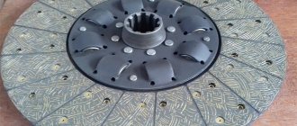
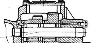
MAZ petal clutch diagram.
184.1601218 Retaining ring 1 184.1601130-10 Driven disk assembly 2 313020-P2 Rivet 3 184.1601158 Thrust pin 4 184.1601153 Damper disk 5 184.1601167 Belleville spring 6 18 4.1601142 Driven disk hub 7 184.1601151 Internal damper spring 8 184.1601150 Damper spring 9 184.1601131 Driven disk with friction linings in assembly 10 183.1601404 Rivet
11 184.1601138 Friction lining
11 184.1601138 Friction lining 12 184.1601132 Driven disk with plates assembled 13 184.1601402 Rivet 14 184.1601134 Driven disk with damper rings 15 184.1601135 Spring plate 16 182.16 01342 Pressure plate plate 16 182.1601342 Pressure plate plate 17 257257-P2 Rivet 17 257257-P2 Rivet 18 252006-P2 Washer 18 252006-P2 Washer 19 45 93481571 Bolt 20 252136-P2 Spring washer 10 21 184.1601090 Pressure disk with casing assembly 22 182.1601343-10 Pressure disk bolt 23 182.1601122 Clutch housing with plates assy 23 182.1601122 Clutch casing with plates assy 24 182.1601344 Bushing 25 182.1601360 Casing thrust ring 26 201464-P29 M8x40 bolt 27 182.1601097 Bracket 28 182.1601364-50 Bushing 29 182.1601275 Retaining ring 30 182.1601273 Sha Spring yoke 31 184.1601115 Pressure spring 32 182.1601120 Thrust ring 33 183.1601093-10 Pressure disk 34 250636-P29 Nut 35 184.1601015 Carter clutch 36 236-1601030-A2 Upper crankcase hatch cover 37 252137-P2 Spring washer 38 310214-P29 Bolt 39 184.1601215-10 Clutch release shaft 40 45 9824 6270 Key 41 238N-1601040 Shaft seal housing 42 238N-1601042 O-ring 43 238N- 1601044 Ring 44 184.1601216 Bushing 45 312399-P2 Washer 46 310012-P2 Bolt 47 252135-P2 Spring washer 48 201454-P29 Bolt M8x16 49 236-1601022-B Card hatch cover Lower bracket 50 184.1601203 Clutch release fork 51 182.1601187 Cracker 52 310213-P29 Bolt
53 184.1601180-31 Clutch release clutch assembly
54 182.1601183 Safety ring 55 182.1601198-10 Ring 56 182.1601199-01 Locking ring 57 183.1601197 Retaining ring 58 183.1601195 Reflective washer 59 46 1214 053 8 Bearing 70-117 60 182.1601193-02 Bearing sleeve 61 184.1601185-30 Clutch release clutch 62 236-1601230-A Bearing lubrication hose assembly 63 182.1601188 Clutch spring 64 182.1601190 Spring bracket 65 260316-P2 Plug 66 45 9167 5005 Oiler 2.3.45 Ts6 67 312695-P2 Washer Link to this page: https://www. kspecmash.ru/catalog.php ?typeauto=6&mark=14&model=670&group=54&part=1867090
Installation of the YaMZ-238 engine and YaMZ-236 gearbox
I quickly unscrewed and removed the engine from the KamAZ with the gearbox, after which I installed the YaMZ-238 engine and the YaMZ-236 gearbox on the frame. The rear engine brackets, intended for mounting the KamAZ engine, had to be cut a couple of times.
Under the front cross member of the engine, I made a mount in place, having previously jacked up the front part of the engine and maintaining the correct inclination of the cardan from the gearbox to the middle axle MOD. The rear gearbox bracket fits the original one, along with the cushion. The flange of the YaMZ-236 gearbox was replaced with a KamAZ four-bolt one.
I gave the radiator to a coppersmith and he re-soldered the pipes for the YaMZ-238 engine. I took the PGU bracket from a friend for the YaMZ-236 gearbox and they made exactly the same one for me based on the original. The tube for the PSU had to be extended locally.
The clutch release shaft from the YaMZ-236 gearbox was previously rotated from the left side to the right. I cut off the long part of the lever from the clutch release shaft and installed it in place, making a new PSU rod for the connecting pin with the clutch release lever.
The hydraulic hose had to be bent several times in order for it to fit between the gearbox and the CCGT. The CCGT took air from the tube that went to the gear valve of the KamAZ divider.
Realizing that the exhaust system would have to be greatly altered in order for the pipes to be routed outside the frame, I went a different route. I found exhaust pants from a MAZ-500 and MAZ exhaust manifolds bent up. With this kit, it was possible to quickly assemble an exhaust system using a standard KamAZ muffler and connecting corrugation.
Soon, the coppersmith called me and said that my radiator could be picked up. I brought it to the garage and began to fit it into place. After several unsuccessful attempts to do this, I took the advice of veterans and turned the diffuser upside down and also re-drilled the holes. Then, I connected the diffuser and radiator, after which I began to install everything in place.
In order not to redo the radiator mountings on the frame, I machined new rubber pads for it (about 50 mm high) and new radiator mounting extension bolts. After that, I secured the radiator and installed all the MAZ water pipes.
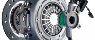
MAZ clutch repair
In the last article we wrote about what a MAZ clutch is and what components this element includes. Today we will tell you in detail how to repair a MAZ clutch. Practical advice and photos of replacing a MAZ clutch will help in repairing a modern truck.
MAZ clutch repair - where to start?
Adjusting the MAZ clutch is much more difficult than repairing the element. We will touch on the nuances of adjustment in the following articles. Now let’s study how to replace the MAZ clutch. Before you start repairing a MAZ spare part, we advise you to think about the causes of the breakdown. The MAZ clutch can fail due to the failure of the driven disk, and due to wear of the bearings, springs and seals. As a result, you may notice that the truck:
- Makes sudden jerks during winding.
- Makes noise when the pedal is pressed and a burning smell.
- Has a discrepancy between acceleration and revolution.
Another reason for MAZ clutch failure is that it is very difficult to change gears.
These wear symptoms can be eliminated by adjusting the clutch.
The very first thing we do is check the CCGT.
MAZ clutch – what you need to know when buying
The MAZ clutch is the most important transmission mechanism of a Belarusian truck and bus, transmitting torque from the engine to the gearbox.
Having problems with your MAZ clutch? Need a new one for replacement and installation?
Which is better and where is it more profitable to buy a MAZ clutch?
If you are faced with one of these questions, take a few minutes to read the article!
High-quality clutch kits installed on the assembly line in Minsk fully comply with the well-known reliability of equipment from the Minsk Automobile Plant. However, any auto part is subject to wear and tear and has its own resource. In order for your truck tractors and dump trucks to continue to work properly, you need to take the purchase of a MAZ release bearing and clutch disc very seriously.
Composition of the MAZ single-plate friction clutch kit
The MAZ clutch assembly is an integral automotive component of a commercial vehicle, the structure of which consists of:
Why is a clutch needed in a manual transmission?
The purpose of this unit is similar for all commercial vehicles, be it MAZ, MAN, KAMAZ, URAL, GAZelle or PAZ. To familiarize yourself with the general functions and characteristics of clutches, follow the links:
Dump trucks, truck tractors and MAZ buses (a little history)
The decision to create the Minsk Automobile Plant (at that time a car assembly plant) dates back to 1944, making it one of the oldest in the CIS countries. From the first truck (timber carrier MAZ-501) to the present day, when a wide range of equipment is produced for almost all types of economic activity, the main principle of design and engineering services is to provide the buyer with high-quality and inexpensive cars.
The MAZ model range includes:
- Truck tractors;
- Flatbed dump trucks;
- Municipal vehicles;
- Scrap trucks;
- Manipulators;
- Garbage trucks;
- Truck cranes;
- Log carriers;
- Farmers;
- Combined machines;
- Other special equipment on MAZ chassis.
The production of passenger vehicles was established in 1992, and during this time MAZ buses became widely known in many countries around the world. This is facilitated by the creation of special versions that take into account regional characteristics and requirements. In particular, a special bus model for Africa is being mass-produced.
The Minsk Automobile Plant does not rest on its laurels, but looks to the future with confidence, as evidenced by a number of facts:
- Fruitful work of the Center for Advanced Development;
- Attracting foreign partners to supply MAZ Euro double-disc and single-disc friction leaf clutches to the assembly line;
- Creation of joint production facilities on the territory of the Republic with leading Asian and European corporations;
- Organizing the production of new models, such as light commercial vehicles (LCVs).
MAZ gear diagram
How does the switch happen?
Different coverage or variations in the absence of it, changes in the topography along the “up-down” vector, movement empty, with an average or full load - each of the proposed cases requires a specific torsion speed of the moving wheels and the force with which all this occurs. An internal combustion engine has certain limits in terms of the numerical expression of frequency and torque; to expand it and gain the ability to be stable in several positions, a gearbox is called upon.
At the same time, automatic transmissions also have clearly defined reactions, and the operation of a heavy truck is often associated with the ability to quickly, sometimes even unexpectedly vary the speed and torque of the drive shafts. Especially if you have to drive along a road whose condition is far from ideal. And since the manual transmission is controlled remotely, using a switch lever, it must know which positions correspond to which torque and speed.
Of course, it would be possible to do something like a linear displacement, but in this case the rocker mechanism would resemble the dimensions of a thick rocker arm, and it is possible that the cabin would become a bit cramped. And this is even with a standard 4- or 5-speed transmission, and we won’t even talk about 9, 12 and 16-speed transmissions. Therefore, designers have to “cram” all the possibilities into a complex, but compact drawing diagram. And it is necessary to remember it because the discrepancy between the selected gear and range means not only problems with overcoming the route, but the risk of increased wear of parts, especially if the “incorrectness” is systematic.
HOW TO SWITCH
The standard version of the control circuit, for example, is present on the 500th MAZ. For those who are able to forget in what order everything happens, a drawing is printed on the handles of the main working tool for changing the speed and transmission. It looks like this:
- — the handle freely walking along the horizontal average vector is “neutral”;
- - left-up - first, -down - reverse;
- - center-down - second, -up - third;
- - to the right - up - fourth, - down - fifth.
In a gearbox with multiplier dividers, the pattern either remains and the upper and lower ranges overlap when the additional box is first initiated, or the pattern itself becomes more complicated, receiving a couple of additional “branches.”
The transmission of “commands” from the handle-lever is transmitted via a transverse roller to the industrial mechanism, and from there through the main rod to the industrial lever. Then a special axial roller “turns on” and sets the gearbox shift lever itself in motion.
For such a “workhorse” as the MAZ-500 and its modifications, due to the loads experienced, problems even with the correct change of gear speed are not uncommon. There are plenty of possible malfunctions due to which the MAZ gearbox circuit does not work as intended, but three options are the most common.
1. The first and rear ones do not “catch” when the others are functioning normally.
• To eliminate such a problem, you need to mark the position of the rod to its tip, loosen the tightening bolts and turn the tip clockwise by about 4-5 degrees (about 1 mm between the marks). Then the bolts are tightened and functionality is checked. If the problem persists further, then we repeat the operation, that is, we move the tip a little more.
2. When the others are working, the 4th and 5th do not work.
• We do the same as in the previous case, but this time the tip must be turned counterclockwise.
3. The system itself works fine, but switching is made difficult by the incorrect position of the lever (for example, the lever rests against the panel).
• Set neutral and disconnect the rod end from the shift mechanism earring. We make sure that the mechanism lever is also in a neutral position - the fork is located vertically, and when angularly rocked, resistance to rotation is felt. If everything is so, then tighten the locking screw on the intermediate mechanism until it stops, thereby “tightly” fixing the intermediate roller. We loosen the coupling bolts and adjust the length of the rod so that the stopper pin easily passes through the holes of the earring and the tip. We connect them and tighten the coupling bolts. After this, unscrew the locking screw of the industrial mechanism five turns and lock it with a nut.