Replacing crankshaft bearings without removing the engine
Replacing crankshaft liners without removing the engine from the car is a very painstaking and extremely inconvenient job.
But it has to be done in order to extend the life of the engine and avoid premature breakdowns. When working at a manufacturing plant, car repairs can be planned. If the repair is ongoing, and even if the car is very necessary. Still trying to make this repair. So that the car works as long as possible until the next breakdown. You eliminate all related problems, following repair technology. Even if there is a shortage of spare parts. No one will remember later that the car stood for a long time for repairs. They will rather be reproached when it breaks again, and for the same reason.
The same cannot be said about repairing cars and other equipment in agricultural conditions. If the car stops during the sowing or harvesting season. This is a tragedy. And if you take a long time to repair it, it’s almost a crime. For five years in my practice I had to work in agriculture. And I take my hat off to the people who have dedicated their whole lives to this.
During the harvest, this happened to me. When changing the oil in the engine of a KAMAZ vehicle, copper shavings began to shine on the oil filters. The first thing, of course, had to be determined was the source. Typically, small chips appear when the crankshaft bearings begin to break. We removed the pan and unscrewed the crankshaft cover closest to the flywheel. Since this is where the liners are subject to the greatest wear. And indeed the liner was broken. There were no traces of beating on the shaft. There was a slight wear characteristic of the crankshaft. We decided to change the liners without removing the engine.
The cost of engine repairs during the harvesting season is aggravated by losses in earnings. If you have your own Kama, you suffer losses every day of downtime for repairs. After all, in agriculture, every day feeds the year. If you work in a company, you lose in salary. Basic earnings are paid during the season, not to mention the losses the enterprise incurs.
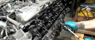
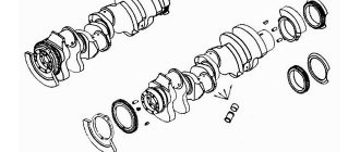
If the crankshaft is not damaged. Or the risks that have arisen on it are not very deep; replacing the crankshaft liners without removing the engine from the car will not take much time. So that the top liners come out easily. The shaft should not be released more or less on one side, so the covers must be unscrewed one at a time. Remove covers 1, 3 and 5. Using a thin screwdriver, tap the end of the insert on the side opposite to the lock. Surprisingly the liner comes out easily.
Then insert the insert from the lock side. We make sure that the lock fits into the groove, insert the liner into the lid and install it in place, the upper and lower liners should be positioned lock to lock, and so on. Pressing the removed covers with a little force, but so that they are pressed tightly against the block, unscrew the remaining covers and carry out the same procedure. Then we tighten the cover bolts using a torque wrench, preliminary tightening with a force of 95-120 Nm and final tightening with a force of 275-295 Nm. Then we tighten the coupling bolts with a force of 147-167 Nm. In the same way, the connecting rod bearings of the crankshaft are replaced without removing the engine.
Source
Repair of the crankshaft, block and connecting rod of the KamAZ engine
To repair the crankshaft, block and connecting rod of the KamAZ engine, seven repair sizes of liners are provided (see Table 10). The designation of the corresponding neck liners, the diameter of the shaft and the diameter of the bed in the block or connecting rod are marked on the back side of the liner.
Table 10. Repair dimensions of liners
| Options | Parameter values depending on the repair size, mm | ||||||
| Neck diameter: | |||||||
| indigenous | 94,485. 94,500 | 93,985. 94,000 | 94,985. 95,000 | 94,485. 94,500 | 93,985. 94,000 | 93,485. 93,500 | 92,985. 93,000 |
| connecting rod | 79,487. 79,500 | 78,987. 79,000 | 79,987. 80,000 | 79,4.87. 79,500 | 78,987. 79,000 | 78,487. 79,600 | 77,987. 78,000 |
| Bed Diameter: | |||||||
| in the block | 100 +0,021 | 100 +0,021 | 100,5 +0,021 | 100,5 +0,021 | 100,5 +0,021 | 100 +0,021 | 100 +0,021 |
| in the connecting rod | 85 +0,01 | 85 +0,01 | 85,5 +0,01 | 85,5 +0,01 | 85,5 +0,01 | 85 +0,01 | 85 +0,01 |
| Insert designation: | |||||||
| indigenous: | |||||||
| upper | 740.1005170Р1 | 740.1005170Р2 | 740.1005170РЗ | 740.1005170Р4 | 740.1005170Р5 | 740.1005170Р6 | 740.1005170Р7 |
| lower | 740.1005171Р1 | 74 0.1005171Р2 | 740.1005171P3 | 740.1005171Р4 | 740.1005171Р5 | 740.1005171Р6 | 740.1005171Р7 |
| connecting rod | 740.1004058P1 | 740.1004058Р2 | 740.1004058РЗ | 740.1004058Р4 | 740.1004058Р5 | 740.1004058Р6 | 740.1004058Р7 |
| Liner thickness: | |||||||
| indigenous | 2,690. 2,702 | 2,940. 2,952 | 2,690. 2,702 | 2,940. 2,952 | 3,190. 3,202 | 3,190. 3,202 | 3,440. 3,452 |
| connecting rod | 2,703. 2,715 | 2,953. 2,965 | 2,703. 2,715 | 2,953. 2,965 | 3,203. 3,215 | 3,203. 3,215 | 3,453. 3,465 |
To remove and disassemble the connecting rod and piston group :
Rice. 84. Removing the connecting rod lower head cover with a puller
When assembling and installing the connecting rod and piston group:
Rice. 86. Piston and connecting rod assembly
Dimensions of parts and permissible wear, mm
* Measure piston ring clearance in caliber 0 (120+0.03) mm
Tightening torques of threaded connections, N.m (kgf.m)
| Main bearing cap bolts | 206. 230,5 (21. 23,5) |
| Cylinder block pinch bolts | 80,4. 90,2 (8,2. 9,2) |
| Crankshaft screw | 49,1. 58,9 (5. 6) |
| Flywheel bolts | 147,2. 166,8 (15. 17) |
| Tightening the connecting rod cap bolts with Ml2 threads until they are extended by | 0.25. 0.27 mm |
| Reinforced bolts with M13 thread | 117,7. 127,4 (12. 13) |
To remove the crankshaft, remove:
When installing the crankshaft on a KamAZ engine :
When tightening the bolts with a torque wrench, the resistance should increase smoothly, without jerking. Count the moment as the key moves. Upon completion of tightening, the crankshaft should rotate freely from hand force applied to the flywheel mounting pins; the axial clearance in the thrust bearing should be at least 0.05 mm.
To disassemble and reassemble the crankshaft:
Repair work
Malfunctions of the KamAZ crankshaft and ways to eliminate them:
- Damage to the main or connecting rod journals, deformation of the seats. In this case, it is recommended to grind the parts to the repair size, apply a coating using electric arc surfacing, and weld the electrical contact strip.
- The thread on the oil scraper ring is worn. It is necessary to deepen the thread using a cutter and grind the neck.
- Defective key, seat and ball bearing. In this case, it is necessary to perform milling to match the increased parameters of the keys, make surfacing followed by milling the key, and press in the bushings.
- Damage to the holes for the flywheel mounting pins. It is necessary to unroll the parts to the repair size.
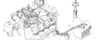
How to remove a bearing
To remove a bearing from the crankshaft, you must:
- Remove all vehicle components that prevent access to the crankshaft.
- Place the power unit block on the stand that is used to repair the engine.
- Remove the flywheel. For comfortable operation, it is recommended to install a locking device on the flywheel crown. Before removal, the position of the mechanism relative to the motor block is noted, and a marking is made as to the sequence in which the mounting bolts were installed.
- Remove the oil pan and oil pump.
- Remove the bearing caps and the connecting rods themselves. They need to be removed along with the pistons.
- Remove the crankshaft.
- Clean seating surfaces.
- Remove the bearing.
How to balance
Procedure for balancing:
- Place the machine in a horizontal position.
- Install the crankshaft on the machine. If there is an imbalance and the shaft begins to rotate around the corner, such an imbalance must be eliminated.
- Using small magnets, determine the exact weight of the metal that needs to be cut. To do this, magnets must be attached to the light side of the flywheel. They are hooked until the crankshaft lies motionless, without overweight. The weight of the magnets is the weight of the metal that must be cut off to balance.
- Remove any chips from the flywheel.
- Trim off excess metal by drilling small holes in the flywheel housing.
- Return the crankshaft back to the vehicle.
How to install
Installing the crankshaft includes the following steps:
- Removing the main bearing cap from the cylinder block.
- Unscrewing the tightening and mounting bolts.
- Selection of main bearing shells in accordance with the diameter of the main journals.
- Selection of thrust rings.
- Checking the liners.
- Installing the upper bearing shells into the cylindrical block, then the lower ones and lubricating them.
- Installing the crankshaft in a vehicle.
- Installing the connecting rod head.
- Screwing the lower and upper half rings.
- Cleaning and lubricating threads in block holes.
- Checking the tightening torque of bolts.
- Inspect the thrust bearing for clearance.
The resistance when tightening the bolts should increase without jerking, smoothly.
KAMAZ 740 crankshaft weight
Product code: 126.103.383
External differences between the crankshaft 740.50 and 740.30: the diameter along the axis of the connecting rod journals is 10 mm larger at 740.50 than at 740.30
A counterweight 740.21-1005026 with a width of 21.5 mm is installed on the shaft 740.30-1005008. (according to the diameter of the seat. The width of the counterweight is 15.5 mm,
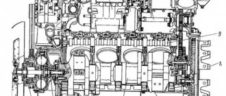
The KamAZ 740 crankshaft is made of high-carbon steel using the hot stamping method and is also hardened using nitriding or hardening with high frequency currents (HFC). The connecting rod and main journals are subjected to hardening. The KamAZ 740 crankshaft has four connecting rod journals and five main bearings that connect the jaws. The crankpins of the shaft are made in such a way that they have cavities inside that are closed with plugs. The cavities are designed for additional oil purification through centrifugal forces.
To balance the centrifugal forces, counterweights are installed on the so-called nose (the front end of the crankshaft) and the shank (the rear end of the crankshaft), which on the cheeks are integral with the shaft, and are pressed onto the nose at the time of assembly and secured using a segment key.
Peculiarities
The oil supply is carried out through special holes provided in the main journals. To balance inertial influences and reduce vibration, six counterweights were installed, made by stamping, like the cheeks. There are also two additional counterweights that are pressed onto the shaft. In the bored socket of the shank there is a pressed ball bearing of the KamAZ 740 crankshaft. The angular placement of the parts relative to the crankshaft is adjusted by keys.
Uniform alternation of operating torques of the KamAZ 740 crankshaft is ensured by the arrangement of the connecting rod journals at right angles. A pair of connecting rods is connected to each element: for the right and left cylinder row.
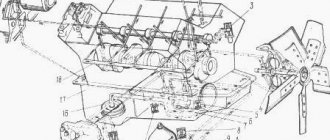
- Front counterweight.
- Rear analog.
- Drive gear.
- Timing drive gear element.
- Key.
- Key.
- Pin.
- Jet.
- Unloading slots.
- Oil supply sockets.
- Holes for the oil line to the connecting rod journals.
Dimensions and other characteristics
Parameters and technical indicators of the KamAZ crankshaft:
What is the price
The average price for a crankshaft is 35,000 rubles.
Crankshaft prices on the market vary widely:
It is not recommended to buy spare parts made in China, as their installation can lead to car damage.
Attention! In Moscow, cases of selling Chinese spare parts under the guise of original ones have become more frequent. Be careful when purchasing, check all technical specifications of the product.
Device
A jet is screwed into the cavity of the front nose of the assembly. Through its calibration socket, lubricant for the power reduction spline shaft is supplied to the drive part of the hydraulic coupling. The KamAZ 740 crankshaft is protected from movement along the axes by a pair of upper half rings and two lower analogues. They are mounted in such a way that the grooves are adjacent to the ends of the shaft.
At the front and rear of the toes of the block there is an oil pump drive gear and a camshaft drive gear element. At the rear end of the part there are eight threaded connections for fixing the torque absorber. The crankshaft is sealed by a rubber cuff, which is equipped with a boot and is located in the flywheel housing. It is made from a fluorine rubber compound directly in the mold.
Types of Kamaz crankshafts
In recent years, the range of crankshafts produced by Kamaz has expanded significantly. Now the plant produces diesel and environmentally friendly gas engines that meet European quality standards. For each engine there are several types of crankshafts.
Crankshafts from different engines are sometimes interchangeable and sometimes not. To date, the Kamaz company does not provide clear instructions on the types of crankshafts, which is why owners of heavy trucks usually have confusion about which crankshaft is needed specifically for their brand of Kamaz. To solve this problem, a description of the crankshafts is provided below:
Crankshafts meeting Euro 0 standard
Engines created according to the Euro-0 standard include standard heavy-duty diesel engines 740.10 and engines of the updated version 7403.10, 7408. For the production of crankshafts for these engines, 42ХМФА standard steel is used, which has undergone special treatment with chromium and molybdenum, and is coated with aluminum. Hardening of the production material occurs with high-frequency currents to a depth of 3 millimeters. crankshafts have special plugs. This crankshaft model has now been discontinued.
Crankshafts operating for Euro 1 standard
Euro 2 engine crankshafts
Engines that meet the Euro 2 standard have different crank radii. That is why the types of crankshafts for different radii have serious differences.
The crank diameter of Kamaz engines is 60 mm (R65). They are equipped with 2 types of crankshafts, which differ from each other in the type of flywheel connection:
The 2 types of parts cannot replace each other.
The crank radius of Kamaz engines can also be (you can see the type of crank on your parts) 65 mm. Crankshafts in which the flywheel is secured with 10 M16 bolts are suitable for them. The parts are interchangeable, but there are differences in the hardening method:
Crankshafts for Euro-3 engine standard
Engines that meet the Euro-3 standard are quite few in number. The crank radius of these engines is 65 mm. In this case, the flywheel can be mounted according to the standard scheme with 8 or 10 bolts. The product is hardened by high frequency currents. They can be replaced with other Euro 2 crankshafts (which have also undergone HDF treatment).
For all crankshafts, the method of mounting the flywheel depends on the type of clutch installed in the car. With the classic configuration, the flywheel is mounted on 8 M14 bolts. On new configuration models, a flywheel connection with 10 M16 bolts is used.
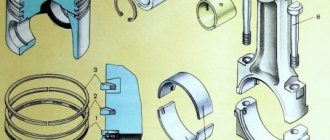
Compression and oil scraper elements
The piston is equipped with a KamAZ 740 crankshaft oil seal, as well as a pair of compression rings and one oil scraper analogue. The distance from the bottom to the lower end part of the upper groove is 17 mm. The piston part of engines 740/11, 740/13 and 740/14 differs from each other in the shape of the ring sockets, and therefore is not interchangeable.
The compression elements are made of reinforced, and the oil scraper ring is made of gray cast iron. On the 740/11 engine, the cross-sectional configuration of the clamps is a one-sided trapezoid. When installing, the upper inclined end is placed on the side of the piston bottom. The working barrel-shaped part of the ring is coated with molybdenum. The surface of the second compression and oil scraper ring is coated with chrome.
When installed, the middle of the expander is located in a special lock. The oil scraper ring is made in a box-shaped configuration; on the 740/11 engine it has a height of 5 millimeters, and on 740/13 and 740/14 - 4 mm.
KamAZ differences between factory-made and Chinese-made crankshafts
The modern market of spare parts for KAMAZ vehicles varies in price and quality of products, in the level of service and responsibility of sellers. Along with the original products of KAMAZ OJSC and its official suppliers, there are products from alternative and “gray” manufacturers on the market. Currently, Chinese manufacturers of spare parts for KAMAZ vehicles are actively trying to penetrate the market. The difference in price for spare parts made in China sometimes reaches 2-3 times and buyers, trying to save on price, fall into the trap when, having replaced a broken part, after some time they are forced to buy the same part again due to its rapid failure. As a result, it turns out that the car is constantly under repair, and its owner, in addition to direct losses from the purchase of spare parts and repairs, also incurs indirect losses from the car’s downtime.
To help the consumer understand the quality of Chinese-made parts, as well as to identify their compliance with the design documentation of KAMAZ OJSC, a crankshaft, mastered by Chinese manufacturers and sold as spare parts in the Siberian trading network, was transferred to the KAMAZ scientific and technical center for research and comparative tests , and which until recently was considered a monopoly position of KAMAZ OJSC,
Below are the distinctive features of a Chinese-made crankshaft, which can be identified during external inspection of the part:
| Shaft made in China | Shaft produced by KAMAZ OJSC |
| On the side surface of the 1st counterweight, the KAMAZ marking is applied in raised font (which is a violation of the law “On the use of a registered trademark”). The side of the counterweight is marked with a partial part number "1005008" in raised font. | On the side surface of the 3rd counterweight there is the marking “KAMAZ” and the full designation of the part, the production date of the crankshaft forging is marked, and on the eighth counterweight there is an OTK stamp. |
| The side and outer surfaces of the crankshaft are not machined and are obtained by casting | The side and outer surfaces of the counterweights are mechanically processed, the crankshaft is obtained only by stamping, and on the backs of the cheeks (at the ends of the connecting rod journals) a mark of trimming the flash is visible. |
| There are no traces of balancing in the form of holes on the counterweights | All crankshafts undergo mandatory balancing. |
In addition, as a result of research, it was determined that the Chinese-made crankshaft is made of high-strength cast iron and does not have surface hardening of the main and connecting rod journals, which does not correspond to the design documentation, according to which this crankshaft must be made of alloy steel and undergo hardening with high-frequency currents. frequency) or nitriding depending on the crankshaft model.
Analysis of measurements of geometric dimensions also showed the unacceptable quality of the Chinese-made crankshaft - more than 90% of the dimensions were made with deviations from the design specifications of KAMAZ OJSC.
When conducting bending fatigue tests on a Chinese crankshaft, the endurance limit could not be determined due to its destruction. Based on this, we can conclude that the endurance limit of the Chinese crankshaft is lower than the working load on the crankshaft on the KAMAZ engine.
The conclusion made by the specialists of the Scientific and Technical Center is that the Chinese-made crankshaft does not comply with the design documentation of KAMAZ OJSC and is unsuitable for use on KAMAZ engines.
The article was prepared by the Bureau of Market Conditions of the Marketing Department of OJSC TFC KAMAZ
Flywheel and journals
The diameter of the main and connecting rod journals of the KamAZ 740 crankshaft is 95 and 80 millimeters, respectively. There are 8 types of restoration inserts that are used for repairs without grinding. The main and connecting rod bearings are made from lead-bronze and tin-plated steel strip. The inserts at the top and bottom of the element are not interchangeable. They are secured against transverse and longitudinal displacement by ledges, which are placed in the grooves of the bearing caps and connecting rod beds. The specified parts are marked accordingly (74-05.100-40-58 and 74-05.100-57-51). The valves and covers are made of high-strength cast iron. They are fastened with bolts, which are fixed according to a regulated pattern. The flywheel is secured with eight bolted studs made of alloy steel, as well as pins with a sleeve. To avoid damage to the assembly, washers are placed under the bolt heads, and a toothed rim is located on the cylindrical surface of the flywheel.