How to adjust the ignition d 245
The need to install (reinstall) the pulse wheels of the crankshaft and the fuel injection pump drive gearbox shaft to synchronize them may be caused by dismantling the fuel injection pump drive gearbox during routine repairs of the diesel engine.
The installation of pulse wheels according to the proposed scheme is carried out to synchronize the signals from the crankshaft speed sensors and the input shaft of the injection pump drive and is ensured by binding the sensor signals to the common reference point of the shaft position at the moment the piston of the first cylinder passes the top dead center (TDC).
To ensure correct installation of the impulse wheels, it is necessary to make a device for fixing the gearbox gear dowel pin in accordance with the sketch (Figure 1).
Figure 1 – Device for fixing the locating pin
Remove the cylinder head cover.
Set the piston of the first cylinder to the TDC position by turning the crankshaft clockwise using bolt 4 (Figures 4a, 4b) until it matches (depending on the design of the impulse wheel):
Figure 2 — Installing the retainer into the hole in the back sheet and flywheel.
a) – the gap in the “crown” of the impulse wheel is made in the form of a segment of depressions;
b) - the gap in the “crown” of the impulse wheel is made in the form of a solid segment):
— a) the axis of the 16th tooth of the “crown” of the pulse wheel (when counting counterclockwise from the gap segment in the “crown” of the pulse wheel) with the axis of sensor 1 Figure 4a;
— b) the axis of the 16th cavity of the “crown” of the pulse wheel (when counting counterclockwise from the segment of the gap in the “crown” of the pulse wheel) with the axis of sensor 1, Figure 4b;
Make sure that the intake and exhaust valves of the 1st cylinder are closed; if the exhaust valve is open, turn the crankshaft a full turn and recheck the condition of the valves.
Install the piston of the first cylinder on the compression stroke (beyond ≈ 60° of the crankshaft rotation angle to TDC), for which:
Figure 4a - Installing the crankshaft speed sensor
Figure 4b - Installing the crankshaft speed sensor
c) for diesel engines with a crankshaft position lock:
— turn the crankshaft clockwise using bolt 4 (Figures 4a, 4b) approximately two turns; on the second turn, unscrew the lock from the threaded hole of the rear sheet in accordance with Figure 2, insert it with the reverse side into the same hole until it stops flywheel and turn the crankshaft until the lock matches the hole in the flywheel;
In this case, the impulse wheel 2 (Figures 4a, 4b), mounted on the crankshaft pulley 3, will be positioned in such a way that the axis of the sensor 1 will pass along the axis of the sixth tooth of the “crown” (design – a), or along the axis of the sixth cavity of the “crown” (design – b), impulse wheel (when counting counterclockwise from the gap segment in the “crown” of the impulse wheel).
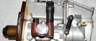
Fuel injection pump of diesel engine D-245 - design and adjustments
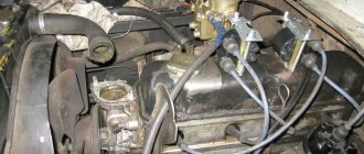
On the D-245 engine of the ZIL-5301 Bychok, GAZ-3309, MAZ-4370 Zubrenok cars, fuel injection pumps-773 are installed. The high-pressure fuel pump is a block design consisting of four pump sections in one housing, having a cam drive of plungers and spool-type dosing of cyclic fuel supply.
TNVD-773 is designed to supply metered portions of fuel under high pressure into the combustion chambers of diesel cylinders at certain points in time. The fuel pump camshaft is driven from the diesel crankshaft through distribution gears.
The relative position of the fuel pump drive gear and the drive coupling half is fixed by tightening the nuts installed on the coupling half studs. The tightening torque of the nuts is 35…50 Nm.
The D-245 high-pressure fuel pump is combined into one unit with an all-mode regulator and a piston-type fuel priming pump.
The regulator has a fuel supply corrector, an automatic fuel enricher (at starting speeds) and a pneumatic smoke limiter (boost corrector). The booster pump is installed on the fuel injection pump housing D-245 and is driven by the cam shaft eccentric.
The working parts of the pump are lubricated with flowing oil coming from the diesel lubrication system. The oil is drained from the pump housing into the diesel crankcase. The newly installed pump on a diesel engine must be filled with oil in the amount of 200.250 cm3. Fill oil through the oil drain hole pos. 30 (Fig. 1).
Fig. 1 – Fuel pump TNVD 773 diesel D-245
1 - fuel pump section; 2 — plate; 3 – flange; 4 – key; 5 – drive coupling half; 6 – nut for fastening the coupling half; 7 – cam shaft; 8 – fuel pump housing; 9 – fuel priming pump; 10 – supporting bracket; 11 – starting feed adjustment bolt; 12 – stop lever; 13 – regulator body; 14 – regulator cover; 15 – inspection hatch cover; 16 – minimum rotation speed adjustment bolt; 17 – bolt for adjusting the maximum rotation speed; 18 – nut securing the fuel pump sections; 19 – bypass valve; 20 – fuel supply fitting; 21– oil line; 22 – fuel outlet fitting from the booster pump to the fine fuel filter; 23 – bolt securing the fuel supply fitting to the booster pump; 24 – boost corrector; 25 – bolt of the air supply fitting; 26 – control lever; 27 – screw plug for adjusting the nominal fuel supply; 28 – air bleed plug; 29 – stop electromagnet; 30 – oil drain hole.
Maintenance of the high pressure fuel pump TNVD diesel engines D-245
During operation of the high-pressure fuel pump 773, when the main parts wear out, its adjustment parameters are violated. Injection pump lubricant D-245 is centralized from the diesel lubrication system through a special oil line. The required oil level in the pump crankcase is set automatically.
To reduce wear of precision parts, it is not allowed to operate the injection pump without a filter element or with a clogged fine fuel filter. It is also not allowed to work with fuels that have a high water content.
If necessary, and also every 120 thousand km, it is necessary to remove the pump and check it on a stand for compliance with the adjustment parameters, as well as the setting angle of advance of fuel injection on a diesel engine. If necessary, make appropriate adjustments.
Motor characteristics. general information
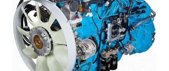
The use of an internal turbine compressor with adjustable air flow makes it possible to create optimal throttle response when the engine is running. This indicator is ensured by an enhanced torque parameter even at minimum shaft speed. Also, the exhaust gases meet all required standards. —
All motors in the series are designed to work at tempo. conditions up to +40 degrees Celsius. The main area of application of these diesel engines is power plants for construction equipment, road equipment and wheeled tractors.
Modifications
The procedure for adjusting the valves is identical for other modifications of the series. Among them is also D-245-06. The engine has a power rating of 105 horsepower, four cylinders and free atm. inlet. The model is installed on MTZ 100/102 tractors. The engine is equipped with a ST-142N starter, generator, as well as a compressor, gear-type pump, pump and clutch.
This installation has an in-line arrangement of cylinders and a turbine charging system. The motor is installed on MAZ-4370 vehicles and is equipped with a 24-volt starter, a compressor with a turbine, a water, oil and gear pump.
The clutch is single-disk. The modification has a power of 108 “horses” and an in-line arrangement of cylinders. Mounted on ZIL 130. The D-245 engine is equipped with a fuel pump and a pneumatic compressor. The timing kit includes fasteners, washers, nuts, pushers, camshafts, disc clamps. —
Characteristics
Before studying the valve adjustment on the D-245 engine, let’s consider its technical parameters:
- Manufacturer: MMZ (Minsk).
- Type - four-stroke in-line diesel engine with an in-line arrangement of 4 cylinders.
- The fuel mixture is supplied by direct injection.
- Compression – 15.1.
- Piston displacement – 125 mm.
- The cylinder diameter is 110 mm.
- Working volume – 4.75 l.
- Cooling is a liquid system.
- Speed – 2200 rotations per minute.
- Average fuel consumption is 236 g/kWh.
- Power indicator – 77 kW.
- Camshaft gear.
- Intermediate gear.
- Crankshaft toothed element.
- TN drive wheel.
Adjusting valves in the D-245 engine
Before you start setting up the D-245 valves, you need to study the features of this unit. The shaft has 5 supports and is driven by the crankshaft and distribution gears. 5 bushings are used as working bearings, which are placed in sections of the block. The front bushing is located in the fan area and is equipped with a collar that secures the camshaft axial shifts; the others are made of cast iron. The steel pushers are overlaid with special cast iron, and the spherical surface has a radius of 750 mm. Angled camshaft cams.
To correctly adjust the D-245 valves, it should be taken into account that the pusher rods are made of steel rod and have a spherical area that fits into the pusher. The valve rocker arms were made of steel, and the axle was fixed using 4 racks. The axis is hollow, equipped with radial holes for oil delivery.
Checking clearances
It is better to check the valves of the D-245 engine in terms of clearances every 15 thousand kilometers. This procedure is also carried out after the cylinder head has been removed, the cylinder head bolts have been tightened, or after a knock appears in the valve compartment. The gap size between the end part of the valve stem and the rocker arm striker on a cold engine is 0.25 mm on the intake valve, and 0.45 mm on the exhaust valve.
To adjust the clearances, it is necessary to loosen the locknut of the rocker arm of the valve being adjusted. Next, by turning the screw, the required value is set (measured using a probe running between the striker of the rod). After the process is completed, the locknuts are tightened and the cap from the cylinder head cover is replaced. The tightening is checked after running in and then every 50 thousand kilometers on a warm unit. After checking, it is necessary to adjust the gap between the rocker arm and the valves, after which you need to tighten the clamps.
Engines of the D-245 model are 4-stroke power plants equipped with 4 cylinders, which are placed vertically in a row. The engine is equipped with a direct injection system, which ensures an increased level of fuel combustion and, accordingly, higher efficiency. However, for the correct operation of the power plant, timely adjustment of the valves of the D-245 engine is required.
Engine D-245
Adjusting the cylinder head tightening
The order in which the cylinder head bolts are tightened determines the sequence and force with which the flywheel bolts are tightened in the threaded connections. It is important to remember that the cylinder head tightening torque should be in the range of 190-210 Nm. In this case, the stud nuts and bolts must be tightened to capacity.
The adjustment process is performed as follows:
Upon completion of this process, according to the indicated scheme, it is necessary to return the rocker arm axis to its original position, and then adjust the clearances of the D-245 valves present between them and the rocker arms.
Valve adjustment D-245
Separately, it is worth considering the procedure for adjusting the D-245 valves. Before starting this process, it is recommended to study the features of this node. So, the camshaft has 5 supports at once, and is driven by the crankshaft, as well as by the distribution gear. Special 5 bushings are used in the form of bearings installed by pressing. At the same time, the front one is made of aluminum and is located in the fan area and is equipped with a thrust collar, which is responsible for fixing the camshaft and preventing its axial shifts. All other bushings are made of cast iron.
In order to correctly adjust the valves, it is necessary to take into account that a steel rod is used to create pusher rods. It has a spherical part that fits directly into the pusher. The adjustment process itself occurs as follows:
After completing the adjustment, wash the cylinder head and the valves themselves. Next, the working elements are lubricated with oil for the power plant. The grinding process can be carried out manually using conventional metalworking tools. But in this case, the time and labor costs for this operation will increase significantly.
The D-245 engine is a diesel power plant, often used in various construction, road or other similar equipment.
For correct operation during long-term operation, it is necessary to adjust the valves and tighten the cylinder head.
If you find an error, please select a piece of text and press Ctrl+Enter.
Diesel power units D-245, the valve adjustment of which we will consider below, are four-stroke piston engines with four cylinders. Internal combustion engines of this type have in-line vertical cylinder placement, are equipped with direct fuel injection and combustion of the fuel mixture as a result of compression. Additionally, the parameters of the unit are improved by turbine charging with intermediate cooling of the incoming air. Let's consider the characteristics of the engine, as well as the possibility of adjusting the valves.
Installation of injection pump, injectors, high and low pressure pipes D-245
The injection pump mating plate must be clean; nicks and other damage to the slab are not allowed.
The fuel pump gasket must not show any visible damage.
When installing the fuel pump, you must align the marks of the fuel pump drive gear and the splined flange.
The splined flange of the fuel pump gear must fit freely, without jamming, onto the splines of the fuel pump shaft bushing.
The fuel pump gear flange mounting bolts must be tightened to a torque of 18…25 Nm.
When installing the fuel pump, be sure to check the fuel injection advance angle. This is done in the following sequence:
- set the regulator control lever to the position corresponding to the maximum fuel supply.
- Disconnect the high-pressure tube from the fitting of the first section and connect the momentoscope instead (Fig. 1).
- Turn the diesel crankshaft clockwise with a wrench until fuel free of air bubbles appears from the glass tube of the momentoscope.
- remove some of the fuel from the glass tube by shaking it.
- Turn the crankshaft counterclockwise 30...40°.
- Slowly rotating the diesel crankshaft clockwise, monitor the fuel level in the tube; at the moment the fuel begins to rise, stop rotating the crankshaft.
- If the latch does not coincide with the hole in the flywheel (Fig. 2), make adjustments by doing the following:
- remove the hatch cover;
- Unscrew bolts 1, 2 and 3 (Fig. 3) and loosen bolt 3 by ½…1 turn (do not unscrew the bolt);
- align the locking rod 2 (see Fig. 2) with the hole in the flywheel, turning the diesel crankshaft in one direction or the other; Using a wrench, turn the fuel pump shaft and splined flange by the nut until the fuel begins to rise in glass tube 1 (see Fig. 1) of the momentoscope;
- install bolts 1,2 and 3 (see Fig. 3) into matching holes, trying to position them as evenly as possible around the circumference;
5. tighten bolt 3 first, then bolts 1 and 2;
- Reinstall the high-pressure tube and remove the locking rod from the hole in the flywheel;
- Replace the hatch cover.
The alignment of the splines of the fuel pump bushing and the splined flange when installed on a diesel engine is ensured by turning the diesel crankshaft or the pump camshaft. Diesel engines must be equipped with injectors of the same group.
The sealing gaskets on the side adjacent to the injectors must be lubricated with solid oil US-1 GOST 33-51.
The injector mounting bolts must be tightened to a torque of 20…25 Nm.
High pressure pipes must be secured at a distance of 10...15 mm from the union nuts with clamps with gaskets.
Low pressure fuel pipes should be purged with compressed air before installation on a diesel engine.
Valve adjustment D-245
Before you begin setting up the valves, you need to study the structure and features of this unit. The camshaft has five bearings and is driven by the crankshaft and timing gear. Five bushings are used as bearings, which are placed in the block bores using the pressing method.
The front bushing is made of aluminum, is located in the fan area, equipped with a thrust collar that secures the camshaft from axial shifts, the other bushings are made of cast iron. Steel valve tappets are coated with special cast iron, the spherical surface has a radius of 750 mm. The camshaft cams are slightly inclined.
To correctly adjust the D-245 (“Euro-2”) valves, it is necessary to take into account that the pusher rods are made of steel rod and have a spherical part that fits inside the pusher. The valve rocker arms are made of steel and swing on an axis fixed by 4 stands. The axis of these elements is hollow, equipped with eight radial holes that serve to deliver oil; the movement of the rocker arms is stopped by spacers in the form of springs.
Label designation
Installation of timing marks on d 240 is carried out according to the gear arrangement diagram
The letter “K” indicates the mark of the intermediate gear and crankshaft.
The letter "P" indicates the position of the camshaft
The letter "T" indicates the position of the fuel pump gear
Peculiarities
The inlet and outlet valves D-245, the adjustment of which we will consider further, are made of heat-resistant steel. They are located in guide bushings, which are pressed into the cylinder head. A pair of springs acts on each element, ensuring its closure using plates and crackers. Oil getting into the cylinders is prevented thanks to the sealing collars that are located on the valve guides. The design also protects the exhaust manifold from flooding, preventing oil from passing through the gaps of the valve stems and guide bushings.
Lapping
Adjustment of valves D-245 (“Euro-3”) is carried out according to the following scheme:
- The nuts securing the rocker arm axle stands are unscrewed, and the axle itself is removed along with the springs and rocker arms.
- The head mount is unscrewed, after which it is dismantled. The valve should be dried out, its plate, springs and washers should be removed, and the seal should be removed from the guide sleeve.
- Adjustment of D-245 valves (grinding) is carried out on special machines or stands. A lapping paste with the addition of stearic fatty acid is applied to the chamfers of the elements.
- The grinding of parts should continue until a continuous matte edge with a width of at least 1.5 mm is formed on the chamfers of the valve and its seat. In this case, breaking of the belts is not allowed. Deviation in width in different areas is no more than 0.5 mm.
- After adjustment, it is recommended to rinse the cylinder head and valves, and then lubricate the working rod with engine oil. Alternatively, lapping can be done manually using bench tools. However, adjustment time and labor intensity increase significantly.
Checking and adjusting gaps
It is advisable to check and adjust the valves of the D-245 (Euro-2) engine in terms of clearances every 20 thousand kilometers. This procedure is also carried out after removing the cylinder head, tightening the cylinder head fixing bolts, or when a knock occurs in the valve compartment. The size of the gaps between the rocker arm and the end part of the valve stem on a cold diesel engine should be 0.25 mm on the intake valve and 0.45 mm on the exhaust valve.
To adjust the clearances, it is necessary to loosen the screw lock nut of the rocker arm of the valve being adjusted. Then, by turning the screw, the required value is set, which is measured using a probe between the striker and the end of the rod. At the end of the process, tighten the locknut and replace the cylinder head cover cap. The tightening of the mounting bolts is checked after running-in and every 40 thousand kilometers on a warm power unit. After checking, it is necessary to adjust the gap between the rocker arm and the valve, and then tighten the clamps.
Source
Checking diesel injectors D-245 for injection start pressure and fuel atomization quality
Fig. 4 – D-245 engine injector
1 – nozzle body; 2 – adjusting washer; 3 – spring; 4 – nozzle rod; 5 – spacer; 5 – sprayer nut; 7 – sprayer; 8 – sealing ring.
Check the injectors every 120 thousand km. Remove the injectors from the diesel engine and check them on a stand. The injector of the fuel pump TNVD 773 is considered to be in working order if it sprays fuel in the form of a mist from all five holes of the nozzle, without separately flying drops, continuous streams or thickenings.
The beginning and end of the injection must be clear; the appearance of drops on the toe of the nozzle is not allowed. Check the spray quality at a frequency of 60-80 injections per minute.
If necessary, adjust the nozzles by changing the total thickness of the adjusting washers 2 (Fig. 4): increasing the total thickness of the adjusting washers (increasing spring compression) increases the pressure, decreasing it decreases it. A change in the thickness of the washers by 0.1 mm leads to a change in the pressure at which the nozzle needle begins to rise by 1.3... 1.5 MPa.
Injection start pressure values for injectors: 455.1112010-50 – 24.5 MPa; 172.1112010-11.01 – 25.0…26.2 MPa. Install the injectors on diesel. Tighten the injector mounting bracket bolts evenly in 2-3 steps. The final tightening torque is 20…25 Nm.