This parameter indicates the time when the combustible mixture is ignited. And it is determined by the position of the crankshaft when an impulse is applied to the spark plugs in advance relative to TDC (top dead center), and is measured in degrees. In order for the working mixture to completely burn out in the cylinder, it takes some time, so if the mixture is ignited at the moment when the piston is in the highest position (TDC), then its combustion will occur during the expansion and exhaust strokes. This will not provide effective pressure on the piston.
Thus, the ignition point should be selected ahead of the curve so that maximum pressure occurs at TDC. The value of this moment depends on a number of parameters, among them: the number of engine revolutions, the quality of the combustible mixture (lean or enriched), its fractional composition.
It should also be noted that detonation can often occur in gasoline engines, even at optimal angles, so you need to set the advance angle a little more.
Hi all! I am a master of fuel equipment, I run my own video blog on YouTube and share the subtleties and nuances of repairing and operating diesel cars https://www.youtube.com/watch? v=-nCMdVoBZIs 09:06 How to set the ignition on a diesel engine (injection timing) 18
Installing a remote engine control system
Eberspächer 4kw engine heater is suitable for 350 d Mercedes or not
Electric winch 12v Electric Winch 12000lbs / 5443 kg reviews
How to set the ignition on a DT 75 engine a 41: comments
Respect. You post quality products!
I think you are making a mistake. I can prove it.
Absolutely right! The idea is good, I support it.
What a useful topic
In my opinion, this is relevant, and I will take part in the discussion. Together we can come to the right answer.
How to set the ignition on a dt 75 engine a 41
Here is one of these hard workers, pretty tired, but working. Tractors produced by PTZ were distinguished by their blue color (Volgograd ones were red, yellow and orange) and the inscription “Kazakhstan” on the sides of the hood; Volgograd machines had a simple inscription “DT-75”. Judging by the color, the model represents a Volgograd tractor, but according to some sources, some batches in Pavlodar were also painted orange. The cunning manufacturers did not make any inscription on the hood at all, which is one of the shortcomings of the model, but allows it to be adjusted to fit the variant of any of the factories.
The sides of the hood are made closed; on working tractors they were often removed to improve ventilation of the engine compartment. Everything seems to be fine at the back, but there is one drawback.
On the live machine you can see details that you were too lazy to make on the model: a sound signal and a socket for connecting agricultural machines. With the exception of these points, the model can be called quite decent.
There were rumors that the twelfth issue might be the last in the series, but, fortunately, they were not confirmed: there will be a thirteenth issue and it will be the MTZ-2 model.
How to set injection timing on a diesel engine. Adjusting the ignition of a diesel engine
Adjusting the ignition angle of trucks in Moscow
Back in the days of contact ignition on gasoline trucks, the term “ignition adjustment” became so common in the colloquial language that it was transferred to diesel engines, although they do not have an ignition system as such. A diesel engine equipped with a mechanical injection pump or pump injectors allows you to adjust only the injection advance angle - the moment at which fuel begins to flow into the cylinder. Moreover, gasoline trucks, which are unprofitable in terms of fuel costs, and diesel engines without electronic engine control, which are outdated and no longer produced, are increasingly leaving the highways. In Common Rail systems, the injection timing is set by an electronic control unit and cannot be adjusted (only flashing the unit is possible). However, our company also offers its services for adjustment work on-site in Moscow and the region (both independently and as part of other repair work - for example, ignition adjustment on a KamAZ engine is necessary after the injection pump drive plates on it have been cut off and new ones were installed).
The technical assistance vehicle is equipped with all special devices for adjustment, if they are required for a specific engine (for example, Bosch fuel injection pumps require fixing the regulator flag with a shaped plate with a slot), so precise adjustment of the injection timing according to the service documentation is guaranteed.
Diesel engine injection pump design
Mechanical in-line injection pump
In-line fuel pump
An in-line injection pump has a number of plunger pairs corresponding to the number of engine cylinders.
In the recent past, almost all diesel engines were equipped with such pumps, essentially representing several pumps (one per cylinder) with a common drive cam shaft. The plunger-bushing pairs are arranged in a row, hence the name – “in-line injection pump”. This type of pump is also called a distribution pump or direct injection pump. An in-line injection pump has a number of plunger pairs corresponding to the number of engine cylinders. The plunger pair is a pump that forces fuel into the fuel tube of the injector. The plunger is driven by a cam mechanism, just as engine valves are driven by a camshaft. After the end of the working stroke, the plunger returns to its original position under the action of a spring. Each stroke of the plunger supplies fuel under pressure to the injector. In order for the fuel mixture to enter the combustion chamber on time, i.e. fuel injection was coordinated with the operation of the connecting rod-piston group and timing, the cams on the pump shaft are installed in accordance with the valve timing - the angles at which they are located seem to repeat the angles of mutual arrangement of the camshaft cams and the working stroke of each plunger occurs during the compression stroke of that cylinder into the nozzle of which this plunger supplies fuel. The injection pump cam shaft is driven through a clutch with a centrifugal injection timing regulator. As the number of revolutions increases, the coupling weights, under the influence of centrifugal force, turn the injection pump shaft against the direction of rotation - to change the timing of the flash advance. In a similar way, on gasoline carburetor engines, the ignition timing changes - due to weights on the distributor shaft.
Operating cycle of a plunger pair
The injection pump fuel supply is adjusted by turning the plungers around their axes.
The plungers have spiral grooves on their side surfaces, connected to longitudinal grooves. The injection pump fuel supply is adjusted by turning the plungers around their axes. As a result of the rotation, the amount of fuel entering the bypass channel changes. The groove, made in the form of a spiral, at different angles of rotation of the plunger, is combined with the bypass channel at different heights, which helps to change the volume of injected fuel. The plunger rotates due to the translational movement of a gear rack that engages with the toothed segment of the plunger. The gear rack is an integral part of the all-mode injection pump regulator, which allows you to control the engine. Through additional mechanisms, it is connected to the gas pedal (on tractors, also to a hand lever that has the same purpose). In addition to the rack, the all-mode regulator has a mechanism that sets it to the maximum feed position after the engine is turned off. This is done to facilitate subsequent startup. After the running engine picks up speed, the all-mode regulator reduces the fuel supply. Fuel is supplied to the injection pump by a low-pressure pump, so fuel lines are divided into two types:
- Low pressure - from the fuel tank to the low pressure pump and to the injection pump; from the fuel injection pump to the fuel tank there is a return fuel line.
- High pressure - from plunger pairs to nozzles.
Rotary distribution pumps
Rotary pumps use control electronics.
Unlike in-line pumps, the plungers in such pumps are installed in the rotor, which is a continuation of the drive shaft. The rotor with plungers rotates in a cam ring made with high precision. At the moment of the working stroke, the plunger, pressed against the cam, moves inward, pushing fuel into the discharge channel of the distributor rotor. Fuel injection occurs when the holes of the rotor discharge channel (the channel is located in the center of the rotor) and the injection pump housing coincide. Of course, the shape of the cam ring and the location of the holes in the distributor rotor are coordinated with the valve timing, which allows injection at a given point in time. The rotation of the drive shaft ensures that the low (intake) and high (discharge) pressure areas operate simultaneously. Such pumps use control electronics, which, in combination with design features, allows for small sizes with high performance.
Operating principle of the ignition system
The ignition system is used for reliable and timely ignition of the combustible mixture entering the cylinder. It consists of a magneto, a spark plug and a high voltage wire.
The operating principle of this element is quite simple and reliable at the same time - when the working mixture enters the cylinder of the starting engine, it is ignited by means of an electric charge formed between two electrodes on the spark plug. For the highest quality charge, a fairly high voltage is required, approximately 10-15 kV, which is created in a special device - a magneto, which combines a number of functions - a breaker, an alternating current generator and a transformer.
The D-240 engines use a magneto with right rotation and a constant spark generation rate. The magneto drive comes from a rigid coupling half through the drive gear on the starting motor.
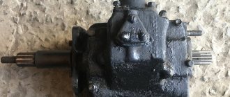
Installing the fuel pump on the engine
Before installation on the tractor, the fuel pump is inspected and the position of the wide slot of its drive flange is determined. After this, turn the pump shaft so that the wide cavity of the spline bushing is against the wide spline of its drive flange. Insert the pump with the mounting journal into the gear hub and engage the splines of the sleeve and flange. Then bolt the pump and connect the low and high pressure fuel lines to it.
When the pump is installed correctly on the tractor, fuel is injected from the injectors into the cylinders at a strictly defined moment. If injection begins long before the piston reaches i. m. t., i.e., earlier than necessary, the fuel enters the cylinder at the moment when the air temperature is below the auto-ignition temperature, the fuel droplets warm up more slowly and, therefore, the delay period increases. If the injection starts too late, the fuel, entering a larger volume of the cylinder, burns slowly or does not have time to burn completely. Therefore, heat loss through the cylinder walls increases, the engine overheats, smokes and does not develop full power.
Fuel must be injected into the cylinder and ignite before the piston enters. m.t., i.e. with a slight advance.
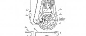
Setting the moment when fuel supply starts:
a - diagram explaining the advance angles of the start of fuel supply and injection; b - location of the momentoscope, indicator arrow and marks on the SMD-14 engine pulley; c - location of the connecting holes in the washer and pump drive gear; 1 — glass tube of the momentoscope; 2 — rubber tube; 3 — a section of steel fuel line; 4 — fuel line union nut; 5 — fitting of the first section of the fuel pump; 6 - arrow; 7 — feed start mark; 8 - mark c. m.t.; 9 — fan drive pulley; 10—splined flange; 11 - pump drive gear
The amount of injection advance is characterized by the angle a (see figure) by which the crankshaft will rotate from the position at the start of injection to the moment when the piston is at b. m.t. In order for fuel to be injected with the required advance, the fuel pump must begin supplying it to the injector even earlier, with an advance angle beta. This is due to the fact that during injection, the fuel is somewhat compressed, the fuel lines expand, and pressure is transferred from the pump to the nozzle in a wave-like manner, although at a very high speed (the speed of sound).
For each engine, factories recommend their own, most favorable advance angles for the start of fuel supply and the start of fuel injection.
To check the moment when fuel begins to flow, glass tube 1 of the momentoscope is installed on the pump fitting instead of the tube going to the injector of the first cylinder. Turn on the supply and rotate the crankshaft to fill this tube with fuel. Shaking it, remove some of the fuel and, slowly rotating the shaft, observe the fuel level in the tube.
At the moment the supply begins, when the fuel level in the tube just begins to rise, the rotation of the shaft is stopped and its position is fixed. To do this, place arrow 6 under one of the nuts of the frame of the SMD-14 and AM-41 engines, near pulley .9 of the fan drive, and mark 7 is placed on the pulley against its tip.
Then, continuing to rotate the crankshaft, place the piston of the first cylinder in. m.t. during the compression stroke and apply a second mark 8 on the pulley against the arrow. The mark (mark) for the start of the feed should be in front of the marks c. m.t. along the arc of the pulley at a distance.
If the starting point of the feed deviates from normal by more than 3°, you need to adjust the advance angle by turning the splined flange 10 relative to the gear 11.
It must be remembered that turning the washer clockwise leads to an increase in the advance angle, and counterclockwise leads to a decrease.
On other engines, the timing of the start of fuel supply is checked and set essentially in the same way as described above.
At the moment the fuel supply begins, the unthreaded end of the installation pin, inserted into the hole in the flywheel housing of the D-50 engine, must fit into the recess drilled in the flywheel; the pointer arrow screwed to the frame of the D-37M, D-37E or D-21 engine must coincide with the “T” mark on the fan drive pulley; The mark on the rim of the flywheel of the D-108 engine must be located from the mark “in. m.t. 1-4 cyl" or "v. m. t. 2-3 cyl", available on the rim, at the distance indicated in the table. 5; The mark on the claw coupling of the fuel pump shaft of the AM-01 or AM-41 engine of the first production must be separated from the mark on the bearing cap of this shaft by a certain amount.
Checking the injection advance angle
After starting, check the operation of the engine in different modes. In case of unstable or hard operation at high speeds, knocking and detonation, black smoke and incomplete combustion of fuel, the injection timing is checked and adjusted. Install the momentoscope on the first section of the pump and monitor the coincidence of the moments when the probe enters the hole in the flywheel and the start of fuel supply to the pump section. The moment of supply before the probe coincides indicates a large advance angle, but if the fuel supply does not start when the probe hits, the injection is late. If the injection timing does not match, correction is made by turning the injection pump shaft. Also open the pump cover, unscrew the two bolts securing the adjusting washer with the bar. To increase the advance angle, turn the shaft clockwise, and in the opposite direction, reduce the injection advance angle. Moving the shaft position by one adjustment hole on the washer corresponds to 3 turns of the diesel crankshaft. By turning the injection pump shaft in the desired direction until the holes on the washer and the gear flange coincide, the injection angle is changed. Assembly is carried out in the same order - install the washer with bolts on the bar in the matching holes.
Clutch for tractor DT-75MV
Single double-disc permanently closed clutches are installed on tractors DT-75, T-74 and T-4.
DT-75 tractor clutch . Clutch device.
DT-75 tractor clutch:
1 - coupling body; 2 and 4 — oilers; 3 — hatch cover; 5 - layering; 6 — adjusting nut; 7 — layering bracket; 8 — release lever; 9 — release bolt; 10 — thrust disk: 11 — pressure disk; 12 — intermediate disk; 13 — driven disks; 14 - flywheel; 15 - crankshaft; 16 — splined bushing for PTO drive; 17 — roller bearing; 18 — clutch shaft; 19 and 34 — springs; 20 - glass; 21 — squeezing rod; 22 — release rod spring; 23 — lever; 24 - transverse roller; 25 - fork; 26 — brake lever; 27 — adjusting bolt; 28 — block; 29 — brake pulley; 30 — front fork of the front coupling; 31 — internal PTO drive shaft; 32 — rear fork of the front coupling; 33 — rear coupling; 35 and 36 — bushings; 37 — connecting bolt; 38 — coupling cage; 39—thrust screw
The clutch discs are placed in the cavity of the flywheel 14 (Fig.), closed by the thrust disc 10.
The drive disks - intermediate 12 and pressure disk 11 - are connected to the flywheel using six fingers 35 (Fig. above). The pins are pressed in pairs into the radial drillings of the flywheel rim, and their square heads fit into three longitudinal cutouts of the drive disks. Thanks to this, both discs rotate together with the flywheel and at the same time can move in the longitudinal direction.
Balancing bolts (not shown in the figure) are screwed into the support disk, with the help of which the new coupling is balanced after assembly. To avoid imbalance, these bolts must not be unscrewed. During assembly, you must also ensure that the “B” marks on the intermediate and pressure disks are aligned with the “B” mark on the support disk.
The driven disks 13 (see figure) are put on the splines of the shaft 18 so that the oil deflectors riveted to the disk hubs face in opposite directions. The front end of the shaft 18 rests on a roller bearing 17 installed in the recess of the offset bracket 7. The mounting band of the bracket fits tightly into the bore of the coupling body, and its flange together with the bearing cover is bolted.
The driving and driven disks are compressed by twelve springs 19 installed in cups 20. Heat-insulating gaskets are placed between the springs and the pressure disk.
The control mechanism has three double-armed release levers 8, which are hinged on fingers in lugs riveted to the support disk. Through the matching holes in the pressure and support disks and in the levers 8, release bolts 9 with countersunk heads are passed. The ends of the bolts are fitted with hinged stops (crackers) and adjusting nuts 6 are screwed on.
A tap 5 with a release bearing is installed on the tubular bracket 7. Her fingers fit into the cutouts of the fork 25, mounted on the transverse roller 24.
The clutch is equipped with a brake, which ensures a quick stop of the driven parts after disengagement. The brake is located outside the housing. Its pulley 29, screwed to the fork 30 of the coupling, rotates together with the shaft 18. Under the pulley there is a block 28 with a friction lining. One side of the block is put on an axis screwed into the coupling body (not visible in the figure), and the other with an adjusting bolt 27 rests on the spring stop of the lever 26. This lever is fixed on the Christmas tree splines of the roller 24 together with the lever 23, which has a rod 16 (see figure .) is connected to the control lever 26.
To disengage the clutch, lever 26 is moved away from you (to the right in the figure). In this case, the lift 32 moves forward and, using levers 33 and bolts 34, pulls back the disk 36. Together with the pressure disk 36, the springs 5 of the release rods 7 move the disk 1 and the rear driven disk 5. The front driven disk 4 is released. The joint movement of disks 36, 1 and 4 continues only until disk 1 reaches three screws 6 screwed into the thrust disk. Then only the pressure disk 36 moves, due to which the rear driven disk 5 is released, and the transmission of rotation to the shaft 3 stops.
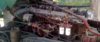
Elimination of floating revolutions.
The barking of the engine occurs when the hazel grouse begins to walk in the splines of the injection pump shaft. Due to the slightest play of the hazel grouse and the fuel injection pump shaft, play is generated during engine operation. The pump, under the action of the plunger springs, begins to change the fuel injection angle and the engine barks.
All this can be eliminated in a simple way. We remove the ignition cover, unscrew the hazel grouse, and pull it out from the landing site. Using a welding machine, we weld small spots into the slots of the hazel grouse. Next, using a diamond file, we adjust it to the size of the pump shaft so that the hazel grouse fits tightly and there is no play.
High pressure pump
This way we will remove the floating speed. If this does not help, then you will have to contact a fuel injection pump repair specialist, which means there is another problem, the pump cracks in the injection pump housing have worn out. The masters will replace them for you. Here are 2 reasons for the floating speed of the D-240 engine that I know.
WATCH THE VIDEO
Clutch basket for DT-75 tractor with A-41 diesel engine:
1 - coupling body; 2 and 4 — oilers; 3 — hatch cover; 5 - layering; 6 — adjusting nut; 7 — layering bracket; 8 — release lever; 9 — release bolt; 10 — thrust disk: 11 — pressure disk; 12 — intermediate disk; 13 — driven disks; 14 - flywheel; 15 - crankshaft; 16 — splined bushing for PTO drive; 17 — roller bearing; 18 — clutch shaft; 19 and 34 — springs; 20 - glass; 21 — squeezing rod; 22 — release rod spring; 23 — lever; 24 - transverse roller; 25 - fork; 26 — brake lever; 27 — adjusting bolt; 28 — block; 29 — brake pulley; 30 — front fork of the front coupling; 31 — internal PTO drive shaft; 32 — rear fork of the front coupling; 33 — rear coupling; 35 and 36 — bushings; 37 — connecting bolt; 38 — coupling cage; 39 - thrust screw.
Installing the ignition on a VAZ (“classic”)
They are equipped with one of two types of ignition. The first is contact: here the opening is carried out by turning the distributor shaft (mechanical method). The second type of ignition is electronic, non-contact: it uses a Hall sensor, which determines the time of spark formation.
How the ignition system works
When the piston reaches the TDC position, it compresses the combustible mixture with maximum force. At this time, a high voltage is formed in the coil. From the distributor cover it is supplied through high-voltage wires to the spark plugs, where a spark is formed that ignites the mixture. When the crankshaft speed increases, the ignition timing changes. This procedure is “carried out” by a vacuum regulator (attached to the ignition distributor), connected via a tube to the intake manifold. As a result, optimal power is achieved in any engine operating mode.
Symptoms of a problem
- the engine cannot be started or it runs extremely unstable (stalls);
- deterioration in driving dynamics: sluggish acceleration;
- increased fuel consumption;
- pops in the muffler;
- vibration during operation of the power plant.
How to set the ignition timing with a strobe light
This is a fairly accurate method that does not require dismantling the valve covers and distributor. The procedure takes literally a few minutes and consists of the following steps:
- with the engine turned off, loosen the nut securing the ignition distributor (key 13), noticing its original position;
- clean the front motor cover (under the pulley) from dirt so that the marks are visible (one long, two shorter);
- Connect the negative terminal of the strobe to the engine ground, the positive terminal to the ignition coil (terminal or nut on the side), fix a separate clamp on the high voltage wire of the 1st cylinder.
- start the engine and point the strobe light at the pulley;
- the mark on it should coincide with the central tide on the front cover of the BC if A80 gasoline is used, and with the longest outer one if the fuel is AI92;
- if this is not the case, smoothly turn the distributor until a match occurs.
Adjusting valve clearances in the engine
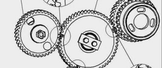
A-41 engine balancing mechanism
To balance the inertial forces that arise during the reciprocating movement of the parts of the connecting rod and piston group, a balancing mechanism is installed on the engine. The mechanism consists of a housing 6, inside of which two unbalanced weight-gears 1 rotate on bearings. The weight-gears are driven into rotation by drive gear 4 mounted on the fourth cheek of the crankshaft. The balancing mechanism is attached from below to the crankcase with two bolts 11: 1 - gear weight; 2 — adjusting gasket; 3 - . pin; 4 — drive gear of the balancing mechanism: 5 — crankshaft; 6 — body; 7 — lock washer: 8 — bolt; 9 — thrust washer; 10 — washer; 11 - bolt.
Technical characteristics of the A 41 engine
| Modification | DT-75 | DT-75M | DT-75N | DT-75D |
| Number of cylinders | 4 | 4 | 4 | 4 |
| Engine displacement, l | 6,33 | 7,43 | 6,33 | 7,43 |
| Cylinder diameter, mm | 120 | 130 | 120 | 130 |
| Piston stroke, mm | 140 | |||
| Compression ratio | 17 | 16 | 16,5 | |
| Specific diesel consumption, g/l. s.ch. (g/kWh) | 195 | 185 (251,3) | 185 (251,3) | 166,9 (226,6) |
| Operating engine oil consumption from fuel consumption, %: | 3 | 1,5 | 1,5 | |
| - general | ||||
| - out of the blue | 0,8 | 0,7 | 0,4 | |
| Engine weight, kg | 720 | 930 | 960 | |
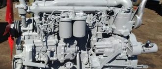
Where is the AMZ A-41 engine installed?
. This motor is equipped with excavators, graders, power plants and pumping units, and other equipment in agreement with the manufacturer. Among the tractors it is used on the T-4, DT-75M, T-4A tractors. Since 2001, engines have been assembled with their own heads for individual cylinder groups, which has improved the reliability of the gas joint and reduced engine oil consumption “waste.” In 2003, a modification was created with electric start, which increased the service life. And in 2012, the crankcase block of the A 41 engine was replaced with licensed German crankcases, which made the engine even more reliable.
The A-41 has a related engine, the A-01, also designed to operate on special equipment. Unlike the A-41, the second engine has 6 cylinders. A-41 engine block
The crankcase is the core of the engine and is a box-shaped cast iron, divided into compartments by vertical partitions. The end walls and vertical partitions of the crankcase have bosses in the lower part that form supports for the main bearing shells. “Wet” cylinder liners are installed in the crankcase. Along the lower seating belt, the sleeves are sealed with three rubber O-rings. The camshaft supports are located in the vertical partitions of the crankcase. A-41 engine cylinder head
One head is installed on the engine, common to all cylinders.
The cylinder head is a cast iron that is secured with studs screwed into the crankcase. The joint between the cylinder head and the crankcase is sealed with an asbestos-steel gasket. The head has a water jacket communicating with the crankcase water jacket. The cylinder head contains valves with springs, valve rocker arms, rocker arms and injectors. The working chamfers of the intake valve seats are bored directly into the body of the head, and the exhaust valve seats are inserts made of heat-resistant cast iron. The crank mechanism (Fig. 9) consists of a crankshaft 2 with a flywheel 13 and liners, connecting rods 5 and a piston set. The crankshaft is made of steel, has four connecting rods and five main journals. The connecting rod journals of the shaft have cavities 21, closed with plugs 4, in which the oil is subjected to additional centrifugal cleaning before entering the connecting rod bearings. Axial forces transmitted to the crankshaft are perceived through the thrust collar by half rings 18. The toe and shank of the crankshaft are sealed with rubber self-clamping cuffs. The bearing shells for the crankshaft and the lower head of the connecting rod are made of bimetallic steel-aluminum strip. The upper connecting rod and main bearings have a hole for oil supply. The liners are secured against axial displacement by stamped tendrils that fit into the grooves of the crankcase, connecting rod and bearing caps. The upper and lower wide liners of the 1st, 3rd, 5th main supports are interchangeable. The upper and lower narrow liners of the 2nd and 4th main bearings are not interchangeable. The flywheel is bolted to the rear end of the crankshaft; the bolts are protected from self-loosening by locking washers, each of which is installed under two bolts. The flywheel is precisely fixed relative to the crankshaft journals with two pins. The flywheel ring gear is designed to start the engine. The connecting rod is steel, I-section, with an oblique connector of the lower head. The connecting rod lower head bearing has replaceable liners. The bearing for the piston pin is a bronze bushing pressed into the hole in the upper head of the connecting rod. The connecting rod lower head cover is secured using a spline lock with triangular teeth, which reliably protects the cover from radial shift relative to the connecting rod. The connecting rod cover fastening bolts are protected from self-loosening by locking washers with whiskers bent at the edge of the bolts and the cover. The piston kit consists of a piston, piston rings, piston pin and circlips. The piston is made of high-silicon aluminum alloy. The recess in the piston crown forms the combustion chamber. Due to the displacement of the nozzle, the combustion chamber is slightly shifted relative to the piston axis in a plane perpendicular to the piston pin axis, in the direction opposite to the camshaft. Five rings are installed on the piston (Fig. 10): three compression rings 10 and two oil scraper rings 11. The set of piston rings is unified with the set of the SMD-60 engine. The oil scraper rings have radial expanders 12. The piston and connecting rod are connected by a “floating type” pin 8, the axial movement of which in the piston is limited by retaining rings 7. Crank mechanism of the A-41 engine
: 1 - oil pump drive gear; 2 — crankshaft; 3 — main bearing shell; 4- plug; 5 — connecting rod; 6 — piston pin; 7 - piston; 8 — cylinder liner; 9 — crankcase; 10 — anti-cavitation ring; 11 — cylinder sealing rings, 12 — flywheel crown; 13 - flywheel; 14 — bearing; 15 — oil seal body with cuff; 16 — flywheel mounting bolt; 17 — oil deflector; 18 — persistent half-ring; 19 — bolt for securing the main bearing cover; 20 — drive gear of the balancing mechanism; 21 — cavity for centrifugal oil purification; 22 — main bearing cover; 23 — clamping washer; 24 - bolt; 25 - ratchet; 26 - bolt; 27 — crankshaft pulley; 28 — oil deflector; 29 - crankshaft gear.
Installation of the balancing mechanism A-41. Catalog 2001
Attention: The electronic auto parts catalog is intended for reference purposes! Our company only sells those products that have prices listed.
Part number on drawing:
Bolt
Serial number: 41-2308-1 Quantity per model: 1
Part number on drawing:
Lock washer
Serial number: 41-2318 Quantity per model: 4
| Number | 6T2-0141 |
| Name | Washer |
| Quantity on "A-41" | 2 |
| OKPO class | 47 Tractors and agricultural machines |
| OKPO subclass | 5 Engines of tractors and agricultural machines |
Part number on drawing:
Washer
Serial number: 6Т2-0141 Quantity per model: 2
Part number on drawing:
Washer
Serial number: 41-2315-1 Quantity per model: 12
| Number | 41-2314-1 |
| Name | Adjusting gasket |
| Quantity on "A-41" | 4 |
Part number on drawing:
Adjusting gasket
Serial number: 41-2314-1 Quantity per model: 4
Part number on drawing:
Roller bearing
Serial number: 12507km Quantity per model: 4