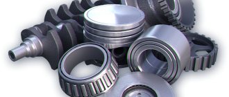
The lower part of the engine crankcase is covered by an oil pan. When driving the car uphill, the presence of a partition located in the sump ensures an even supply of oil to the engine. An oil intake with a strainer is attached to the pump, thanks to which the process of cleaning and supplying oil to the oil pump, which is installed in the engine sump, takes place. The pump type is a two-section gear pump, it is bolted to the cylinder block and is driven by the crankshaft.
The oil is transferred to the rubbing surfaces by a lubrication pump, which also serves to generate pressure in the system. The pump section is formed using borings located in the upper part and the housing in which the gears are located. The forks and keys contain the driving gears, and the driven gears are located in the axle. During operation, oil fills all the recesses between the teeth and moves permeably to the holes. The front part of the pump supplies oil to the main oil strip. The rear part, in turn, transfers oil to the filter and to the radiator and is called the radiator. All parts have valve guards, which limit the maximum pressure at the outlet of the section. In the discharge part of the engine there is a differential valve, thanks to which pressure is maintained in the oil flow.
Two types of oil filters are available in this type of engine. The first is full-flow, all the oil that was supplied by the injection section passes through it and the main oil purification takes place in it. And through the second passes the oil supplied by the radiator section. Filter elements are made from specially impregnated paper; they are replaceable and have high throughput. You can also use filter elements made from wood flour. To drain the oil there are plugs located in the caps. When dirty or at low temperatures, the bypass valve opens without passing through the filter elements, which helps avoid wear and breakage of parts.
From the radiator section, oil enters the filter, causing the rotor to rotate. Thanks to the centrifugal force, the mechanical elements settle on the walls of the cap and clean oil enters the oil cooler; if it is turned off or the pressure exceeds the permissible level, the oil is discharged into the engine sump. If the filter becomes dirty, the bypass valve allows oil to be transferred to the radiator.
There are special marks on the valve and rotor and when disassembling you need to align both. In spring or summer, the oil cooler cools the oil and ensures stable engine operation. To turn off the radiator, the air temperature must be less than zero Celsius and is turned off using a tap located on the filter housing.
There is a filler pipe on the flywheel housing, thanks to which the oil is cleaned. The discharge section of the pump transfers oil to the filter, where it undergoes a cleaning process and enters the crankshaft through channels to lubricate the bearings.
Dirt traps serve as an additional cleaning level before feeding it to the connecting rods. Oil is supplied to the fan fluid coupling through an oil pipeline and also to the compressor. Oil flows to the bearings through grooves in the block. The remaining rubbing parts are lubricated with oil mist or spraying.
The piston pin supports are lubricated by oils removed from the cylinders, which also lubricate the bearing heads. If the radiator is closed, the cleaned oil immediately falls into the sump, fuel vapors and exhaust gases enter the engine crankcase, which can adversely affect the operation of the engine and cause oil leakage into the crankshaft seals. For this case, crankcase ventilation was installed.
Maintenance of the engine lubrication system must be carried out according to the maintenance schedule. Oil filters are changed at every oil change. Failure of the lubrication supply system to the engine, or disruption of its operation, can lead to engine failure and a decrease in its efficiency. To repair and maintain the lubrication system of the YaMZ 236 engine, it is necessary to use high-quality URAL 4320 spare parts. It is important to beware of counterfeits and low-quality consumables, of which there are a lot on the spare parts market for Ural and KAMAZ vehicles today. supplies only high-quality auto parts and components for the YaMZ engine and provides a guarantee for the supplied products.
The waybill is assigned a number, the date of its issue and the name of the organization are indicated (address and telephone number are also possible). The lines provided for information about the driver indicate his last name, first name and patronymic, driver's license number and license card registration number. In the lines for information about the car, indicate its make and state registration number. The medical worker and mechanic (or other authorized person responsible for the technical condition of the car and authorizing departure) put their signatures below.
Section I “Assignment to the driver” indicates the routes, the name of the cargo and (or) the purpose of the trip.
In Section II “Operation of the driver and the vehicle,” the dispatcher (mechanic or other designated person) records the speedometer readings. At the end of the period for which the waybill was issued, the driver hands it over to the dispatcher. The dispatcher certifies the accuracy of the instrument readings taken with his signature on the waybill. Then the accountant receives the waybill from the dispatcher.
Based on the speedometer readings, the accountant determines the mileage of the car. Fuel consumption is determined according to approved fuel consumption standards and vehicle mileage.
Lubricate all points of the URAL-4320 vehicle lubricated with engine oil.
The shaft of the parking brake expansion cam and the threads of the parking brake adjusting mechanism are lubricated with oil used for the engine, 7-10 drops at every second service.
Ticket 6
Purpose, design and operation of the clutch of the KAMAZ-4310 vehicle.
The clutch serves to briefly separate the engine and transmission when changing gears and smoothly connect them when the car starts moving.
Cars use friction clutches. The operation of such a clutch is based on the use of friction forces. Discs made of material with a high coefficient of friction serve as friction surfaces. Depending on the transmitted torque, it is necessary to use a different number of friction elements, so the clutch can be single- or double-disc.
Springs are located around the circumference between the pressure plate and the clutch housing (support plate),
clamping the driven disk between the pressure plate and the flywheel. As a result of the friction that occurs between them, torque is transmitted from the engine to the drive shaft of the gearbox.
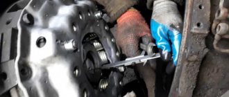
KamAZ-4310 vehicles are equipped with a friction dry double-disc clutch. On the KamAZ-4310 vehicle the clutch drive is hydraulic with a pneumatic booster. The clutch is called frictional and dry because the transmission of torque in it is carried out due to the friction forces between the disks, the surface of which must be dry; The disks are compressed by springs; The torque is perceived by two driven disks. The clutch parts are located in an aluminum housing bolted to the flywheel housing. On top of the crankcase there is a hatch for inspection of clutch parts; the hatch is closed with a lid. The bottom of the crankcase has two hatches, also closed with lids. A crowbar is inserted through the front (small) hatch to rotate the flywheel. The rear hatch cover has a threaded hole for grease drainage; Before crossing the ford, this hole is closed with a plug screwed into the blind boss of the lid. The clutch consists of driving and driven parts, a pressure device and a release mechanism with a drive.
Daily maintenance of the Ural car
During daily maintenance, they carry out general monitoring of systems, components and assemblies that ensure traffic safety, carry out work on refueling and maintaining the proper technical condition of the vehicle. The operation of wheel cranes is also checked on the Ural-375K vehicle.
During a control inspection before leaving the line, you must:
- inspect the car and make sure there are no leaks of fuel, oil, brake and coolant, check the oil level in the engine crankcase and the coolant level in the radiator, fill the windshield washer pump reservoir with water;
- check the operation of the generator using the ammeter reading, the operation of lighting and alarm devices, the operation of control devices and the windshield wiper, the condition of the rear-view mirrors;
- make sure that the parking and service brakes, as well as the steering, are in good condition;
- check the serviceability of the locks of the cab doors and the sides of the platform, the reliability of the fastening of the subframe and fifth-wheel coupling device, as well as the serviceability of the semi-trailer braking system.
When returning from the line you must:
- refuel the car, clean the cabin and platform, and wash the car if necessary;
- drain the condensate from the air cylinders, in winter, when storing without a garage, drain the water from the cooling system and from the starting heater and close the wheel valves (vehicles with a centralized tire pressure regulation system).
The procedure for issuing a waybill.
The waybill is assigned a number, the date of its issue and the name of the organization are indicated (address and telephone number are also possible). The lines provided for information about the driver indicate his last name, first name and patronymic, driver's license number and license card registration number. In the lines for information about the car, indicate its make and state registration number. The medical worker and mechanic (or other authorized person responsible for the technical condition of the car and authorizing departure) put their signatures below.
Section I “Assignment to the driver” indicates the routes, the name of the cargo and (or) the purpose of the trip.
In Section II “Operation of the driver and the vehicle,” the dispatcher (mechanic or other designated person) records the speedometer readings. At the end of the period for which the waybill was issued, the driver hands it over to the dispatcher. The dispatcher certifies the accuracy of the instrument readings taken with his signature on the waybill. Then the accountant receives the waybill from the dispatcher.
Based on the speedometer readings, the accountant determines the mileage of the car. Fuel consumption is determined according to approved fuel consumption standards and vehicle mileage.
Lubricate all points of the URAL-4320 vehicle lubricated with engine oil.
The shaft of the parking brake expansion cam and the threads of the parking brake adjusting mechanism are lubricated with oil used for the engine, 7-10 drops at every second service.
Ticket 6
Purpose, design and operation of the clutch of the KAMAZ-4310 vehicle.
The clutch serves to briefly separate the engine and transmission when changing gears and smoothly connect them when the car starts moving.
Cars use friction clutches. The operation of such a clutch is based on the use of friction forces. Discs made of material with a high coefficient of friction serve as friction surfaces. Depending on the transmitted torque, it is necessary to use a different number of friction elements, so the clutch can be single- or double-disc.
Springs are located around the circumference between the pressure plate and the clutch housing (support plate),
clamping the driven disk between the pressure plate and the flywheel. As a result of the friction that occurs between them, torque is transmitted from the engine to the drive shaft of the gearbox.
KamAZ-4310 vehicles are equipped with a friction dry double-disc clutch. On the KamAZ-4310 vehicle the clutch drive is hydraulic with a pneumatic booster. The clutch is called frictional and dry because the transmission of torque in it is carried out due to the friction forces between the disks, the surface of which must be dry; The disks are compressed by springs; The torque is perceived by two driven disks. The clutch parts are located in an aluminum housing bolted to the flywheel housing. On top of the crankcase there is a hatch for inspection of clutch parts; the hatch is closed with a lid. The bottom of the crankcase has two hatches, also closed with lids. A crowbar is inserted through the front (small) hatch to rotate the flywheel. The rear hatch cover has a threaded hole for grease drainage; Before crossing the ford, this hole is closed with a plug screwed into the blind boss of the lid. The clutch consists of driving and driven parts, a pressure device and a release mechanism with a drive.
The leading parts include the flywheel, housing, pressure and middle discs.
The driven parts include two driven disk assemblies mounted on the splines of the transmission drive shaft.
The pressure device includes twelve springs located between the casing and the pressure plate; A washer and a heat-insulating ring are placed under each spring on the pressure plate side. The release mechanism includes four levers with a thrust ring, a support fork with a nut, a clutch with a bearing, and a release fork with a shaft. The clutch is controlled by a release mechanism. The release bearing is moved by the fork and the pedal rod .
The bearing presses on the inner ends of the levers
,
and the outer ones move the pressure plate away from the driven one, and the clutch disengages. When the pedal is released, the pressure plate, under the action of springs, presses the driven disk against the flywheel - the clutch is engaged.
Maintenance No. 1 (TO-1) of the Ural car
When carrying out maintenance-1, it is necessary to carry out all daily maintenance work, lubricate the components according to the lubrication chart and, in addition, perform the following work. On the engine, check the connections and fastenings of the exhaust system and muffler pipes.
During the first 6,000 km of the vehicle, tighten the cylinder head bolts at each maintenance-1, and subsequently - after one maintenance-1. After all bolts are tightened, tighten the bolts further. After each tightening of the cylinder head bolts, check and, if necessary, adjust the gaps between the valve stems and rocker arms.
After one TO-1, check and, if necessary, tighten the engine mounts, check the tension of the drive belts when pressing with a force of 3-4 kgf, drain the sediment from the sediment filter, clean the centrifugal filter (centrifuge) and the air filter.
In the transmission, through one TO-1, check and, if necessary, adjust the amount of free play of the clutch pedal.
In the chassis of the car, through one TO-1, you should check and, if necessary, tighten the nuts of the wedges for fixing the pins of the front springs, the nut of the eye bolt of the front springs, and the nuts of the pins of the reaction rods.
In the steering system, check the oil level in the power steering pump reservoir.
In the vehicle brake system, adjust the gaps between the pads and drums and check the fastening of the compressor bracket.
In the electrical system, through one TO-1, rinse the breaker contacts with clean gasoline, check the density and level of the electrolyte, and the state of charge of the batteries.
FEATURES OF OPERATION OF CARS URAL-4320-10, URAL-4320-31
PREPARING A NEW VEHICLE FOR OPERATION
Before operating your new vehicle, please read this instruction manual, perform daily maintenance, and additionally:
1. Install on the vehicle according to the operating manual the accessories placed in the spare parts box.
2. Check and, if necessary, adjust the tension of the drive belts.
STARTING AND STOPING THE ENGINE
The order of operation when starting the engine depends on its thermal state, as well as on the ambient temperature. The electric starting system of the engine ensures its start at temperatures down to minus 10 ° C without heating. At outside temperatures below minus 10 °C, use a heater.
For insufficiently charged batteries and in order to increase engine life, the plant recommends using a pre-heater even at outside temperatures above minus 10 °C.
Starting the engine without heating
The procedure for starting a cold engine at a temperature from 0 to minus 10 °C:
1. Prime the engine system with fuel using a manual fuel priming pump.
2. Set the gearbox control lever to neutral.
3. Close the radiator curtain.
4. Turn on the batteries.
5. Set the engine stop handle to the working position (move it all the way to the panel).
6. Press the clutch pedal all the way.
7. Press the fuel control pedal to a position corresponding to the average crankshaft speed.
8. Without releasing the pedal, turn on the starter by turning the key clockwise all the way to the right.
9. After starting the engine, turn off the starter by releasing the key switch, hold the fuel supply control pedal in the position corresponding to the average crankshaft speed until the start of steady -
engine operation, and then smoothly release the clutch pedal (the gear shift lever should be in neutral position). Use the speed control knob to set the minimum crankshaft speed. The constant rotation speed of the engine crankshaft is set by pulling handle 7 (see Fig. 23) toward you. The handle is connected by rods to the fuel injection pump regulator control lever and is located in the cab on the front panel. If the engine does not start, repeat the start in the above sequence. If after three attempts the engine does not start, find and repair the problem. The starter activation time should not exceed 15 seconds and the intervals between starting attempts should not be less than 1 minute.
Before starting a warm engine, set the fuel supply control pedal to the position corresponding to the average engine speed. Turn on the starter and after the engine starts, release the key switch.
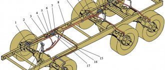
Lubrication system Ural 4320
The lubrication system includes the engine sump, oil intake, pump, full-flow and centrifugal oil filters, radiator, filler pipe, oil level indicator, breather, instrumentation, lines and pipelines.
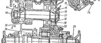
The trough-shaped engine sump is the main oil reservoir and is bolted to the engine crankcase flange through a rubber-corb sealing gasket. The oil contained in it is cooled due to heat exchange with the environment through the walls of the pan. To ensure an uninterrupted supply of oil when driving on inclines, descents and slopes, and to reduce its splashing, a partition is installed in the pan. According to the layout conditions on the KamAZ-5320 vehicle, the deep part of the sump is located in the rear part of the engine, on the KamAZ-4310 and Ural-4320 vehicles - in the front part of the engine. The oil is drained from the bottom of the pan through a drain hole closed with a plug. On earlier 740 engines, the oil pan has two drain holes.
The oil aborator provides primary purification of the oil and supplies it to the pump. It consists of a housing with a strainer, a suction tube with a flange and mounting parts. The oil intake is attached by the suction tube flange to the oil pump housing. The design of the oil intake for the engines of KamAZ-5320, KamAZ-4310 and Ural-4320 vehicles differs in the length of the suction tube. On the KamAZ-5320 engine, the suction tube is longer and curved, as a result of which it has an additional attachment point via a bracket to the crankshaft main bearing cover.
Promotional offers based on your interests:
Rice. 2.13. Engine oil pick-up! KamAZ 5320 1 — latch for fastening the intake mesh; 2 - mesh filter; 3 - body; 4 - suction tube; 5 — bracket; 6 - flange
The oil pump creates the necessary pressure in the lubrication system and supplies oil under pressure to the rubbing surfaces of engine parts. The pump is gear-type, two-section, driven by the crankshaft nose gear.
The pump consists of two sections separated by a spacer. The spacer has a hole connecting the suction cavities of both sections, which provides them with power from one oil intake. Each section consists of a pair of spur gears. The housings of 1.5 sections and the spacer are connected with bolts. The drive gears are pressed onto the shaft and secured with segment keys. At the outer end of this roller, a pump drive gear 6 is installed on a key. The driven gears rotate freely on an axis on bronze bushings. Each pair of gears operates in special borings made in the housings. When the gears rotate, their teeth capture oil at the inlet hole of the spacer, carry it near the walls of the housing and squeeze it out into the outlet holes.
The front section of the oil pump with extended gear teeth has a higher capacity and pumps oil into the main line (discharge section).
Both sections of the pump are equipped with safety valves, which are installed in the housings and adjusted to an opening pressure of 850...950 kPa (8.5...9.5 kgf/cm2) in order to limit the maximum pressure at the outlet of the pump sections. The injection section is equipped with a differential valve located in the housing of the injection section, which maintains oil pressure within the range of 400...550 kPa (4.0...5.5 kgf/cm2) in the main line of the engine.
Rice. 2.14. Oil pump: 1.5 - section housings; 2.4 - drive gears; 3 — spacer; 6 — pump drive gear; 7.8 - driven gears; 9, 11 — safety valves of sections; 10 - differential valve
The oil filter cleans the oil supplied by the pressure section of the oil pump to the main oil line. The filter is full-flow, with two replaceable filter elements, installed on the right side of the cylinder block. It consists (Fig. 2.15) of. housing, two caps, two filter elements and a bypass valve.
Filter elements and caps are attached to the filter housing with screws. A bypass valve is installed in the filter housing, which ensures the supply of crude oil to the main line in case of excessive contamination of the filter or increased oil viscosity. The valve opens when the pressure difference before and after the filter elements reaches 250...300 kPa (2.5...3.0 kgf/cm2). When the bypass valve is activated, the contacts of the signaling device are simultaneously closed and a lamp on the instrument panel in the driver’s cabin lights up, indicating that the engine is running on unclean oil.
Rice. 2.15. Oil purification filter: 1 - screw-rod; 2 - retaining ring; 3,7, 13 — washers; 4, 24 — sealing rings”; 5, 9, 16 — springs; 6 — sealing cup; 8, 11, 18, 19, 27 - traffic jams: 10 - blame the signaling device; 12, 20, 22, 28 — gaskets; 14 — signaling device body; 15 — movable contact of the signaling device; 17 - bypass valve; 21 — body; 23 — body bushing; 25 — filter element; 26 — cap
Rice. 2.16. Centrifugal oil purification filter: 1 - housing; 2 — rotor cap; 3 - rotor; j filter cap; 5, 8, 9 — Krel-genius nuts of the rotor cap, rotor, ULTRA cap; 6 — thrust ball bearing; thrust washer; 10, 13 upper and lower rotor bushings; 11 — rotor axis; 12 — rotor turbine; 14, 15, 16 — pin, plate, stopper spring; 17 — oil drain pipe; /в, 19, 20 - plunger, spring, bypass valve plug
The supply of raw oil to the main oil line through the bypass valve protects engine bearings and other rubbing parts from increased wear and possible failure. However, even short-term operation of the engine on unclean oil is unacceptable, as it causes scuffing of rubbing parts and ultimately damages the engine. The warning lamp can only illuminate when the engine is started and warmed up with cold oil in the lubrication system.
The degree of clogging of the filter elements is determined on a warm engine at a rotation speed of 260 rad/s (2600 rpm). The glow of the lamp in the driver's cabin indicates the need to replace the filter elements.
Since 1979, paper filter elements with increased throughput have been installed in the oil filter. In the summer, if necessary, filter elements with a composition of wood flour and binding materials are used.
A plug is used to drain the oil from the filter.
The centrifugal oil filter provides additional purification of the oil from technical impurities. A filter with an active-reactive rotor drive is installed in the front part of the engine, on the right. The main parts of a centrifugal filter (Fig. 2.16) are: a housing with a filter bypass valve and an oil cooler drain valve, a rotor with upper and lower bushings assembled, a rotor turbine, a rotor axis and a rotor cap. The rotor assembly with the cap is mounted on a thrust ball bearing on the rotor axis, screwed into the filter housing, and secured with nuts. The rotor impeller 12, made of zinc alloy, is fixed to the lower part of the rotor with screws. The rotor cap is closed on top by a fixed filter cap. A stopper is installed in the lower part of the housing to secure the rotor when disassembling the filter. The joints of the connected parts are sealed with gaskets and rings.
Maintenance No. 2 (TO-2) of the Ural car
During maintenance No. 2, it is necessary to carry out the scope of work TO-1, lubricate the components according to the lubrication chart and additionally carry out the following operations. On the engine, check the fastening of the fan and radiator, disassemble and wash the fine fuel filter. After one TO-2, remove the cylinder heads and clean the combustion chambers, valves and pistons from carbon deposits, clean and rinse the crankcase ventilation valve and the connecting pipe.
In the transmission, check the play in the splined joints and crosspieces of the cardan shafts and the fastening of their flanges. When loosening the bolts securing the support plates of the crosspiece bearings, tighten them and secure them by bending one eye of the locking plate to the edge of the head of each bolt. If there are significant radial and end clearances in the crosspiece bearings, the hinges should be disassembled and, if necessary, the bearings and crosspieces should be replaced.
Tighten the fastenings of the ball joints, gearbox, power take-off, bearing caps of all shafts. Check the tightness of the bolts securing the main gear housings to the axle housings. After one TO-2 check and, if necessary, adjust the front axle pin bearings. After two TO-2 checks and, if necessary, adjust the axial play of the drive and intermediate shafts of the transfer case and the position of the gearshift clutch, and adjust the drive axle gearboxes. In the chassis, check the fastening of the reaction rod brackets, tighten the fifth wheel coupling and the nuts of the front and rear springs.
After one TO-2 check the condition of the frame: side members, cross members, brackets, as well as bolted and rivet connections. Replace loose or cut rivets with bolts.
Tighten the balancer mounting nut as far as it will go, and then loosen it until you can turn the balancer by hand. Tighten the balancer nut pinch bolt.
In the steering system, check the fastening of the steering mechanism, power steering, swing arms and steering rods, and tighten loose threaded connections.
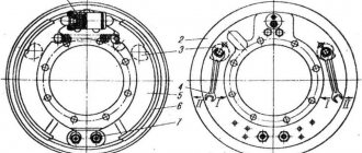
Check the amount of free play of the steering wheel and the amount of toe-in of the front wheels. In the brake system, after one TO-2, remove the pneumatic boosters, wash all parts in kerosene, wash the parts of the master cylinder in alcohol. Replace cuffs with risks and hooks.
When assembling, coat the pneumatic booster parts with a layer of CIATIM-201 lubricant, and the main cylinder parts with castor oil or brake fluid. In order to maintain the installation dimensions, disassemble the rod with pistons only when it is necessary to replace the cuffs.
Remove the brake valve for disassembly and inspection. Remove the cylinder covers, remove the pistons, clean and lubricate.
Inspect and clean the service brakes, to do this, remove the pads, clean the axles and bushings of the pads and lubricate them, disassemble the working cylinder, wash the inner surface and parts in alcohol. Before assembling, lubricate the pistons and cylinder bore with DT-1 lubricant or castor oil. During inspection, check the reliability of fastening of the brake shields and working cylinders, the tightening of the support pin nuts and the condition of the brake pads.
If the brake linings become oily, remove the drum and wash them with gasoline.
After two TO-2s, remove the parking brake drum, clean the axles and knuckle, and lubricate them before reassembling.
After three TO-2, remove the compressor head, clean the pistons, valves, seats, springs and check the tightness of the valves. Valves that do not provide tightness should be ground to the seats, and worn or damaged ones should be replaced with new ones. Rub new valves onto the seats until continuous annular contact is obtained when checking for paint.
Specifications
| Overall dimensions of the car, mm | 7746x2550x3065 |
| External overall turning radius along the buffer, m | 11,4 |
| Service brake system | Double-circuit with pneumohydraulic drive |
| Cabin | All-metal, three-seater, equipped with a ventilation and heating system |
| Cabin | All-metal, three-seater. Equipped with a ventilation and heating system |
| Wheel formula | 4x4 |
| Control fuel consumption at a speed of 60 km/h, l/100 km | 24 |
| Maximum speed, km/h | 90 |
| Weight of transported cargo, kg | 3600*/4200 |
| Platform | Metal with side and rear folding sides, fittings for fastening the container body, equipped with removable arches and an awning, side folding and removable middle benches, attachment points for removed arches, awning, benches, sides |
| Total weight of the towed trailer, kg | 7000 |
| Total weight, kg | 11500*/12100 |
| Transmission | Five-speed gearbox, two-speed transfer case with center differential lock, rear axle with cross-axle differential lock |
| Fuel tank capacity, l | 210 + 60 |
| Ground clearance, mm | 400 |
| Tires | 425/85 R21 KAMA-1260, KAMA-1260-1, 390/95 R20 KAMA-Ural with adjustable pressure |
| Distribution of total vehicle weight, kg | |
| To the rear axle | 6545*/7490 |
| To the front axle | 4955*/4610 |
| Overcoming obstacles | |
| Brod, m | 1,75 |
| Climb, % | 58 |
| Engine | |
| YaMZ-236M2 | |
| Rated power at 2100 1/min, kW (hp) | 132 (180) |
* for a multi-purpose vehicle. At the customer's request, the vehicle can be equipped with a winch (maximum traction force 10-11 t.p., cable length 60 m), YaMZ-236BE2 engines with a power of 250 hp, YaMZ-236NE2 with a power of 230 hp. with a corresponding change in traction and dynamic characteristics.
Engine
For 2022, the YaMZ-236NE23 engine is installed in this car. It is characterized by the following main points:
- the fuel is ignited by compression;
- type - V-shaped;
- equipped with six working cylinders;
- equipped with turbocharging.
Its working volume determines cross-country ability. The size of the combustion chamber is 11.15 liters. Rated horsepower is 230. This is quite enough for driving over rough terrain and undeveloped roads. The maximum torque is 883 N*m, the nominal crankshaft speed is 2080 min-1.
The most important advantage of this engine is its unpretentiousness to the type of fuel. At the same time, it fully complies with the Euro-4 standard, which makes it possible to use this truck in European countries. The engine produces almost no environmental pollution. At the same time, it is important to remember that in winter you need to use special diesel fuel. Since the car's fuel line is not heated, it is not protected from freezing in any way.
Engine repair is not a serious problem. Since all the necessary spare parts are presented in stores, they are publicly available. Due to the simplicity of the device, operational repairs will not be difficult to carry out in the field. This is one of the reasons for the popularity of the car in the army.
— (this is the design of the block in CSS)
Ural-43206 was equipped not only with diesel engines, but also with gasoline engines - ZIL-375.
This engine has the following parameters:
- 180 hp;
- 8 working cylinders;
- The cylinder block is made of cast iron.
Most of the engine was made of aluminum. Which made it easy. Liquid cooling made it possible to “maintain” the nominal temperature even under heavy load in the hot summer. But a small number of models with a gasoline engine went into production. Since the consumption is relatively high, and the cost of gasoline is an order of magnitude higher.
Power system, fuel consumption
The power supply system does not have any serious features. Injection is carried out using an injector developed at the Yaroslavl plant. Main parameters of the fuel supply system in Ural-43206:
- fuel tank capacity - 300 l;
- additional fuel tank capacity - 60 l;
- air supply system - through a cardboard filter;
- exhaust gases - through a muffler;
- cooling system - liquid, with forced circulation and closed type.
Despite the rather impressive power, the car is relatively “economical”. At an average speed of 60 km/h while driving along the chassis, the consumption for every 100 km of travel is approximately 24 liters. This indicator is set for ideal conditions. That is why when driving over rough terrain it may differ slightly.
Transmission
The unique operation of the transmission is another reason for the popularity of this car. The clutch is dry, friction type, with a diaphragm type spring. It is produced at the same plant where the engine installed in the Ural-43206 is assembled. A manual gearbox is used.
This box is designated as YaMZ-236U. Automatic transmissions are not installed on this car model for a number of different reasons. The gearbox itself is five-speed. There are 4 speeds for forward movement and one for reverse movement. Synchronizers are installed in all gears except first. There is a transfer case.
The transmission of torque to the wheels through the box is carried out using a cardan shaft. This greatly simplifies the process of servicing the entire chassis. The cardan itself is of an open type; hinges on needle-type bearings are used. Gear shifting is carried out by disconnecting the gearbox from the engine using the clutch. The algorithm is standard.
The following types of the Ural-43206 vehicle were produced for various needs:
- equipped with 2 bridges;
- equipped with 3 bridges.
Chassis
When assembling this car, the frame is stamped and riveted. Ural-43206 is equipped with special towing devices at the front and rear:
- Rigid towing hooks are mounted in the front part of the body;
- in the rear part of the body there is a traction coupling device.
The front and rear suspensions are equipped with special semi-elliptic springs. There are double-acting hydraulic shock absorbers. There is a spare wheel holder at the rear of the cab. The chassis allows both the driver and passengers outside the cabin to feel relatively comfortable.
Load capacity, tire size, ground clearance
This model is also popular due to its load capacity and excellent cross-country ability, depending on the type of tires used. Dimensional and mass parameters:
- wheelbase size - 4,405 mm;
- length - 7,902 mm;
- width excluding rear view mirrors - 2,965 mm;
- height with fully loaded weight - 2,965 mm;
- vehicle load capacity - 4 tons;
- permissible total weight - 12 tons.
ID-P284 tires are used as standard. Their dimensions are as follows: 1200*500-510. Overall dimensions may vary slightly depending on the body type and other factors. The varieties are shown in the pictures below.