How to make a horse-drawn plow with your own hands will be of interest to anyone who is looking for an adequate option and instructions. Many have tried to make a plow in the likeness of a real horse or tractor plow. But usually such attempts ended in failure. A negative result is not a lack of will and patience, but a lack of skills and knowledge in the field of product geometry.
Design and operation of the plow
The main working parts of the plow are the knife, skimmer and body. If we look at the structure and operation of the plow in more detail, we can add that sometimes an angle bar and a subsoiler are installed on the plow. The auxiliary parts of the plow are a frame with a mounted or trailed device, deepening and deepening mechanisms, support wheels.
The quality of plow work depends on the shape of the body (working surface) formed by the moldboard and ploughshare.
- field board
- sidewalls with heel
- dump
- rack
- ploughshare
The work process consists of cutting off part of the soil from below, lifting it and sending it to the dump. The blade, shifting the layer to the side, partially crumbles it and turns it over, throwing it into the furrow. The layer moves due to the shape of the plowshare-moldboard surface, with the plowshare and mouldboard installed at an angle to the furrow wall and bottom.
Plow bodies differ in the shape of the working surface on
- cultural
- cylindrical rukhadlovye
- screw
- semi screw
- universal
The most common are semi-screw and cultural cases. Good crumbling and wrapping of the formation is ensured by bodies with a cultural surface. Such buildings are used for plowing fallow and virgin lands and old arable soils.
However, in the case of fallow and virgin lands, half-screw bodies are more effective; they wrap the sod layer better, since this type of blade has a wing more bent towards the layer that is being wrapped. When the plow moves, with soil pressure on the body, due to its lateral pressure, the plow tends to move towards the plowed part of the field.
Against this, a field board is attached to each body, to the bottom of the stand, increasing the supporting surface of the plow, which in turn prevents the plow from moving. A plow for non-mouldboard plowing lifts the layer cut by the ploughshare and then it goes to the expander. In this case, the formation crumbles and the soil loosens.
Do-it-yourself plow
The detailed design diagram is that if the soil is mainly made of clay, then it must be processed using small-sized equipment, which is divided into independent units. It looks like this: the plow is placed on one edge of the earth, and the engine is placed on the opposite edge, and they begin to move towards each other.
The plowing cycle is the sequence and change of idle and standard speed in working mode. But this should not be scary, since such a unit has its advantages. The first plus is its compact size. A horse plow can easily fit in the trunk of a car. Secondly, the product weighs little, and any representative of the stronger sex can lift it. You can make a plow yourself, and the materials for making it are freely available and, by the way, are not that expensive. The horse plow is used for:
- plowing;
- cultivation;
- harrowing.
Using a plow, you can easily make recesses under a strip foundation, dig drainage ditches, and perform other construction work.
Plow diagram
The plow is divided into main parts (plow diagram):
- skimmer 1
- Pavilion 2
- knife 4
- frame 3
- support wheel adjustment screw 6
- support wheel 5
- tow hitch 7
Sometimes a hydropneumatic fuse is installed on plows; this is done for processing old arable soils that are clogged with stones of various shapes and sizes, partially protruding to the surface or hidden in the thickness of the layer. Its main components are: a hydraulic cylinder, a pneumatic hydraulic accumulator (PHA) with a piston and fitting, a valve, a pressure gauge, and oil lines.
Each plow body is controlled by articulated supports and a beam. For better wrapping and crushing of the formation, a chisel, a feather and an angle are installed on the body.
How to adjust a plow for plowing
1. Adjustment of the plow for plowing should begin with its working parts. The main working element of the plow is the ploughshare; when plowing, more than half of the load falls on it. The plowshare must be sharpened accordingly. Otherwise, fuel consumption will increase by 20%, productivity will decrease by almost 20%, and the processing depth may decrease by more than a third.
2. The blades of the plowshares must have attachments with a cutting edge of up to 1 mm, a sharpening angle of 25 - 400. These attachments must be made of hard alloys and of the same size. Deviations should not exceed: blade length 15 mm, back length 10 mm, and width 5 mm. Make sure that all bolt heads are recessed to 1 mm or flush. At the junction of the share and the blade there should be no gap exceeding a millimeter, and the blade itself should not protrude more than two millimeters.
3. It is important that the plowshare and blade are on the same line on the field side. The permissible protrusion of the ploughshare is no more than half a centimeter. It is unacceptable for the body stand to protrude beyond the field edge of the blade and ploughshare. The permissible gaps are: between the stand and the plowshare 3 mm, and between the stand and the blade 6 mm.
4. It is necessary to check the field boards on the plow; they must be level. Their back part should be in the same plane with the edge of the ploughshare. The permissible deviation is no more than half a centimeter.
5.The blade of the ploughshare must be installed parallel to the installation site. Elevation of the rear part is permissible no more than a centimeter. Installation of bent beams and/or skewed frames is not permitted. Otherwise, the correct overall position of the plow body is disrupted. The correct installation of the plowshares can be checked as follows: pull the cord along the heels and toes of the rear and front housings. The permissible deviation of the heels and toes should not exceed plus or minus from the tensioned cord.
How to remake a walk-behind tractor
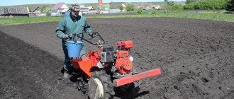
Many owners want to improve their walk-behind tractor to improve comfort during work. The most common modifications are the manufacture of adapters and trailers. This upgrade allows you to expand the functionality of the walk-behind tractor, because the adapter allows you not only to transport various loads, but also to use the walk-behind tractor as a vehicle.
Improving the walk-behind tractor will allow you to create a whole mini-tractor. Adapters and trailers can have their own steering, which is much more convenient than using a steering wheel from a walk-behind tractor. There are many step-by-step photo instructions and videos showing how to create a trailer. One of the most important elements of such a device is the frame, which is made of channel or pipes. Wheels can be taken from any car; the ideal option is wheels from an ATV. Bridges can be taken from VAZ 21-09, they need to be shortened. The steering column can be taken from the same car. The driver's seat will allow you to work with maximum comfort.
In addition, a mini-excavator can be made from a walk-behind tractor, the creation of which requires a hydraulic system. Such an excavator is very convenient for construction on a personal plot, because it is compact and can go where heavy equipment cannot.
Plow moldboard and its applications
The moldboard of the plow - its working part of the body is designed to lift a layer of soil that is cut by a ploughshare. The plow moldboard deforms the soil layer, turns the top layer down and dumps it into the furrow. Based on the shape of the working surface, plow moldboards are divided into semi-screw, screw, cultivated and cylindrical.
According to their design, they are divided into composite (two parts), roller, rod, plate, etc. Blades are made of 2 or 3-layer hardened steel. There are plows for plowing speeds of up to 12 km/h (high-speed plowing); they use moldboards with a special shape of the working surface, which ensures good plowing, normal formation turnover and a continuous plowing surface.
Installing a plow on a walk-behind tractor: step-by-step steps
Before you attach the plow to the walk-behind tractor and start setting it up, the draft unit itself must go through a number of preparatory procedures. They boil down to:
- transporting the walk-behind tractor to where it will be used;
- dismantling the wheel travel, which is replaced by lugs. Otherwise, the equipment will begin to slip and may get stuck.
Once these requirements have been met, installation of the plow can begin.
- fastening the plow to the hitch of a walk-behind tractor with nuts, which will allow you to independently set its operating parameters in the future;
- prepare two fastening pins with which to attach the hitches and plow to the shackle.
This completes the task of installing the plow and you can move on to the next one.
Working parts of the plow
The working parts of plows are cutting or disk knives, skimmers and main bodies.
A disc blade is a disc that rotates on two ball bearings. It is usually installed in front of the rear body, used on general-purpose plows, as well as for soils not clogged with tree roots and stones on bush-marsh plows. A cutting knife is a handle that goes into a knife and is a dihedral wedge. These are used when plowing stone-clogged, soddy soils.
Rotary plow on a walk-behind tractor: advantages of the unit
It has the most advanced form for plowing virgin soil and areas overgrown with weeds to a depth of about 30 cm. A homemade rotary plow includes:
The walk-behind tractor on which such a tool is mounted must have a working power take-off shaft. It is he who drives the axle, and she – the plowshares.
Homemade rotary plows for walk-behind tractors are most often found with disk mechanisms. But drum, blade and auger plows are also known. Indispensable for applying fertilizers and controlling weeds.
Horse plow: features and manufacturing algorithm
HORSE PLOWS AND HORDERS
PLOWS They are intended for basic tillage with 1 rotation of the layer. Basic tillage is usually the first deepest tillage of the soil after cultivating the previous crop. Such plows come in hanging and trailing types.
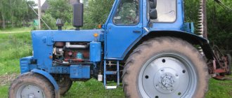
HANGING PV-25. used for plowing old arable soils to a depth of 16 cm. The working width is 25 cm. The plow consists of a beam 4 (Fig. 1), a body 1, a cutting knife 3, a harness hook 9, a regulator that includes an arc 5 attached to the end of the beam , a clamping bracket 6 with a bolt and a vertical bar 8, handles 2 and a support wheel 10. It keeps the front end of the beam from turning in the horizontal plane during operation. When plowing, the support wheel, as a rule, is not used, so the front end of the beam seems to hang above the surface of the field, which is why the plow received the name hanging. If the beam is equipped with a support wheel, then the plow is called a semi-forehead plow.
ADJUSTMENT In order to correctly adjust the PV-25 plow and the main position of the harness hook, it is necessary to know the conditions of its equilibrium in the longitudinal-vertical and horizontal planes. In the longitudinal-vertical plane, the center of gravity is at point O (Fig. 2). The projection of the center of gravity to the bottom of the furrow (point 01) is called the trace of the center of gravity. During operation, the plow is acted upon by the force of gravity G and the traction force P. If the force P passes through the trace of the center of gravity, then its vertical component P2 is balanced by a part of the force G, and the horizontal component P1 causes the movement of the plow. In this case, the plow will move steadily, that is, move at a given depth, since there are no moments of force acting on the plow. If the force P is higher than the trace of the center of gravity, for example through point O, then an overturning moment occurs with a shoulder equal to the distance from point O to the bottom of the furrow. The depth of the plow will increase. If a support wheel is installed on the plow, it will be subject to increased load. This will increase the depth of the wheel rut, which means the traction resistance of the plow will increase. If the traction force passes below the center of gravity, then the overturning moment will contribute to the deepening of the plow from the soil. Hence the conclusion is that when the harness hook moves upward, the depth of the plow stroke increases, and downward it decreases. The height of the hook relative to the supporting surface of the body (bottom of the furrow) can be determined by the formula:
(h + a) = (H + a) x 1/(L + 1),
where L is the length of the lines; H—height of the lines on the clamp; a is the specified plowing depth; 1 - distance from the trace of the center of gravity 01 to the hook. In the horizontal plane (Fig. 3), the plow will move steadily, that is, its working width will be constant, with the least traction resistance, if the traction force passes parallel to the wall of the furrow through the trace of the center of gravity. The line of action of gravity G of a single-furrow plow passes through the point determined by the joint line between the plowshare and the moldboard and the longitudinal vertical plane drawn at a distance of 5 cm from the wall of the furrow. The position of the harness hook 9 (Fig. 1) is determined: firstly, by the height of the distance (h + a) (Fig. 2) from the supporting surface of the body (regulated by a vertical bar 8), and secondly, horizontally 5 cm from longitudinal-vertical plane drawn through the field edge of the blade (regulated by clamping bracket 6 with bolt 7).
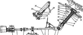
ADVANCED PP-28. designed for plowing both medium and heavy turfy soils to a depth of 18 cm. Its working width is 28 cm. It is pulled by two horses. One goes along the surface of the field, the other along the bottom of the furrow. ' This plow, unlike the hanging one, has a limber (Fig. 4), on which the front end of the beam rests. The front end has one axle shaft 22 of the field wheel 1 and another of the furrow wheel 3. They can be moved relative to each other using a tension bracket. Attached to the axle shaft of the furrow wheel is a vertical frame 21 with two rows of holes for attaching a transverse bar 19 with a saddle 20. The bar with a saddle can be moved in height and moved to the right or left. To do this, there is a longitudinal slot on the right end of the bar, and a row of holes on the left. A horizontal bar 18 with holes for adjusting the positions of the harness hook 24 is attached to the vertical frame. The frames together with the hook are moved relative to the axle axis of the furrow wheel. The beam 16 is connected to the front end using two chains 4, one of which has a coupling nut 5. The chains are connected by a round link (ring) to the draft of the harness hook, and the ends are connected to the hooks of the cross member 17 of the beam. Chain 23 supports harness hook 24.
INSTALLING THE PLOW TO A SPECIFIED DEPTH To ensure that the furrow wheel does not come into contact with the wall of the furrow during operation, the middle of the saddle 20 of the regulator is installed at a distance of + 5.6 cm (in is the working width of the body) from the vertical plane drawn through the inner edge of the furrow wheel. The plow is placed on a flat horizontal platform so that its body rests on the ploughshare blade and the field board. Then the length of the chains is equalized, and a block equal to the specified plowing depth is placed under the field wheel. The axle shaft of the furrow wheel is installed parallel to the supporting surface, and the draft of the harness hook is installed at an angle of 18.20°. Tension the chains and raise the transverse bar 19 so that the beam rests on the saddle 20. Check the adjustment of the plow by plowing it in the field. At the same time, we must remember that moving the transverse bar with the saddle up reduces the plowing depth, and moving it down increases it. The working width of the plow also depends on the position of the cross bar with the saddle. If you move it to the right, the working width decreases, and if you move it to the left, it increases. After plowing the plow, note the location of the wheel axle shafts relative to each other and the position of the transverse bar with the saddle on the vertical frame. This allows you to quickly restore this adjustment after the plow has passed the first and second furrows. To make the first furrow, the plow body is set to half the specified plowing depth. The field wheel is lowered so that it is in the same plane as the furrow wheel, and the transverse bar with the saddle is lowered by approximately two holes (Fig. 5a). After the first furrow, the plow is adjusted to the second, raising the field wheel to half the specified plowing depth relative to the furrow wheel (Fig. 5b). The body will be immersed in the soil to a specified plowing depth. After making the second furrow, using previously made marks, the initial adjustment of the plow is restored (Fig. 5c). The adjusted plow turns out to be so stable in operation that it almost frees the plowman from controlling it by the handles. Such plows are called “self-propelled”.
Drawing of plow parts for walk-behind tractor
You can draw up a layout diagram of functional and structural elements and a detailed drawing of the plow yourself. Maximum accuracy will allow you to avoid difficulties during assembly and the negative impact of errors on the performance characteristics of the finished unit. It is necessary to strictly adhere to the dimensional parameters of the parts. Even minor inaccuracies can have a significant impact on equipment performance. The drawings with the dimensions of the attachment for the walk-behind tractor include three structural surfaces:
- The plane of the slide is lateral.
- Bottom horizontal.
- Front dump.
A typical diagram of a simple homemade plow consists of:
- Two handles made of steel pipe.
- Frames.
- Stand clamp with screw size M10 or M8.
- Mounting fork for frame hinge.
- Drawbar.
- Bearing.
- Jumpers between handles.
- Joint shaft.
- Locknuts.
- Adjusting washer.
- Drawbar handles.
- Tee.
Depending on the type and purpose of the inventory, this list may include other elements.
Reversible plows
Reversible plows are distinguished by the shape of the plowshare, which resembles a feather. A plowshare with a curved upper part turns over the soil. Recommended for plowing hard, hard soil. Plows of this type are compatible with walk-behind tractors of medium and heavy classes, for example MTZ. They got their name from a device that rotates the ploughshare when changing the direction of plowing, which is convenient for long areas. The direction of the soil dump is maintained.
Do It Yourself (Ogonyok) 1996-06, page 65
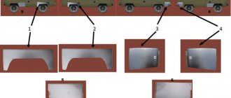
front plow into the soil:
a - passage of the first furrow;
b - passage of the second furrow;
c - restoration of the initial adjustment of the plow to a given plowing depth
touches the wall of the furrow, the saddle is fixed so that its middle (recess) is at a distance of b + 5.6 cm (b is the grip width of the body) from the inner edge of the furrow wheel.
To do this, the plow is installed on a flat horizontal platform so that the plow body rests on the ploughshare blade and the field board, the length of the chains is equalized, and a block equal to the required plowing depth is placed under the field wheel.
The axle axis of the furrow wheel is oriented parallel to the supporting surface, and the draft of the harness hook is oriented at an angle of 18.20° to the horizontal. Tension the chains and raise the cross bar so that the beam rests on the saddle.
Check the adjustment of the plow by plowing it in the field.
Please note that moving the cross bar with the saddle up reduces the plowing depth, and moving it down increases it. The working width of the plow also depends on the position of the cross bar with the saddle. If you move it to the right, the grip width decreases, and if you move it to the left, it increases.
After plowing the plow, note the location of the wheel axle shafts relative to each other and the position of the transverse bar with the saddle on the vertical frame. This will allow you to quickly restore this adjustment after the plow has passed the first and second furrows for the horse.
To make the first furrow, the plow body is set to a plowing depth equal to half the specified depth. To do this, the field wheel is lowered to the ground so that it is on the same plane as the furrow wheel. At the same time, the transverse bar with the saddle is lowered approximately two holes (Fig. 5, a).
After making the first furrow, the plow is adjusted to the second furrow. To do this, raise the field wheel relative to the furrow wheel to a height equal to half the specified plowing depth (Fig. 5, b). In this case, the plow body will plunge into the soil to the required plowing depth. After making the second furrow, using the marks previously made during plowing, ensure the necessary adjustment of the plow (Fig. 5, c).
The adjusted plow turns out to be so stable in operation that it almost frees the plowman from controlling it by the handles. Therefore, such plows are called “self-propelled”.
REVERSAL PLOW PO-23
The reversible plow (Fig. 6) is designed for smooth plowing, that is, for plowing without breakaway furrows and fall ridges.
Horse plow: features and manufacturing algorithm
Plowing is one of the most energy-intensive jobs. The amount of required traction force when plowing depends on the plowing depth, working width, type of soil, its mechanical composition, humidity, degree of weediness, and topography. With normal traction, the horse walks freely, moving the plow smoothly and evenly. If the resistance is high, the horse walks unevenly, sometimes speeding up, sometimes slowing down, making frequent stops. The quality of plowing is greatly reduced. The condition of the plow has a great influence on the amount of required traction force when plowing. A plow, properly adjusted to the appropriate depth and width, moves steadily along the furrow without creating additional resistance. When a plow is correctly assembled, the following basic requirements must be met: the plowshare must be adjacent to a level area with its entire blade; local gaps at the junction of the ploughshare and the blade on the working surface - no more than 1 mm; along the line of the field edge, the blade should not protrude beyond the ploughshare, and the ploughshare can protrude beyond the blade by no more than 5 mm; on the side of the furrow, the edge of the ploughshare can be no more than 10 mm longer than the edge of the blade at the junction; The thickness of the ploughshare blade should not exceed 1 mm. It is necessary that the field board fits tightly to the stand. The rear end of the board and the toe of the ploughshare should be located in the same longitudinal vertical plane. The deviation of the heel of the ploughshare towards the non-plowed field is no more than 5 mm. The skimmer and cutting knife are installed relative to the main body, as shown in Fig. 1. The plowing depth of a hanging plow is adjusted by the height of the harness hook. When plowing shallowly, the harness hook goes lower to the ground, and when plowing deeply, it rises. If the harness hook is stationary or there is no vertical comb, the plowing depth can be adjusted by the length of the lines. The shorter the lines, the shallower the plowing will be. The front plow is adjusted as follows. The first furrow is made by placing the field wheel of the plow at the same level as the furrow wheel, and the saddle of the front frame is lowered 3-4 holes below the working position. In this case, the plow will go deeper to approximately half the normal plowing depth. The second furrow is made by raising the field wheel to half the required depth, with the saddle in the same position. In this case, the ploughshare is buried almost to its full depth. For the third and subsequent furrows, the field wheel is raised from the supporting plane of the body to a height corresponding to the full depth of plowing, and so they continue to work. In this case, the saddle is moved to its normal position if the depth of the second furrow is sufficient; if the depth is insufficient, the saddle is left lowered on the third furrow and only from the fourth furrow is it returned to its normal position. To change the working width (which is done only in exceptional cases), you need to loosen the four nuts of the brackets securing the front frame to the furrow axle, move it to the desired side and tighten the nuts again. The saddle is moved away from the middle position very rarely, for example, when, after prolonged work or careless handling of the plow, the beam becomes skewed relative to the stand. In this case, the plow will deviate to the side during plowing - into the furrow or into the field. If the plow moves into the furrow when the furrow wheel is in the correct position (at the wall of the furrow), the saddle must be moved to the left; if it moves in the field, to the right. Rearrangement of the harness hook along the adjusting arc is carried out when plowing on a slope so that the plow does not slide down, and with different lengths of the arms of the wagon in the double-horse harness. The field wheel can be moved higher or lower so that the front axis is always horizontal both when plowing the first furrow and when plowing to any depth (within the limits of possible depth). When plowing small-contour areas with horse-drawn plows with right-turning bodies, the following methods of movement are used: routing or waddling; circular with loopless one-way turns; penless-circular method (see Fig. 2). The quality of plowing is determined mainly by three main indicators: plowing depth, levelness and ridgeness. Correct adjustment of the plow and selection of horses according to the required traction force on the hook will allow you to avoid overloading the horses, which leads to their rapid fatigue and loss of performance, as well as to carry out plowing in the best agrotechnical terms and with high quality. Note to horse owners. Currently, our industry produces two types of horse-drawn plows: the reversible plow PG-25 and the hanging plow KVP-27A. The first is produced by the Kutaisi Motoblock Plant, the second by the Polotsk Plant of the Ministry of Local Industry of the BSSR. PG-25 is designed for plowing areas located on slopes to a depth of up to 20 cm, and KVP-27A for light and medium soils to a depth of up to 12.5 cm.
G. EGOROV, Art. engineer of the horse technology department at VNIIK
Read it yourself, share it with a friend
| Rice. 1. Diagram of the PP-28 plow in working position. Rice. 2. Movement pattern: a - dump; b - waddle; c - penless-circular method; g - circular with loopless turns. Article rating: Horse plow: features and manufacturing algorithm Link to main publication Related publications
|