The manufacturer's motivation for equipping the MTZ 82 with a beam axle is to strengthen the front part of the tractor chassis. Frequent use of the machine in forestry, construction and other industrial sectors involves operation with loading equipment, which increases the load on the front axle of the tractor. The traditional portal front drive of the tractor, with its technical characteristics and track adjustment capabilities, is more intended for work in the cultivation of row crops in agriculture. Using a tractor with front-mounted loading equipment under constant overloads on the chassis leads to frequent breakdowns of the portal front axle. To strengthen the front end of the MTZ 82, the manufacturer proposed equipping the tractor with a reinforced beam front drive axle with planetary spur final drives.
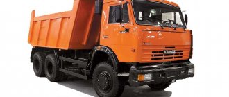
MTZ 82 with beam FDA
MTZ 82 driving front axle and its maintenance
The front axle of the MTZ 82 is a drive axle, and its design determines the high ground clearance and variable track width of the tractor. This functionality allows you to use the machine when processing tall agricultural plants, as well as moving between rows. Like any other systems and components, the front axle requires periodic maintenance, adjustment and repair - otherwise the risk of failure of the MTZ 82 tractor increases significantly.
Drive front axle diagram
- Front axle design and purpose
- Rear axle device
- Maintenance and repair principles
Tractor identification provisions
The fundamental legal source of digital identification of a machine is the factory passport for the tractor. All subsequent registration of property documents and other certificates regulating liability to government authorities are drawn up on its basis. When changing the numbered units of a self-propelled vehicle, the procedure for making changes to the factory passport is carried out under the control of state technical supervision on the basis of presented property documents (checks, invoices, sales contracts) for the replaced units.
The discrepancy between the actual numbers of the machine and its units and those indicated in the documents is not allowed and is the basis for prosecution by regulatory government bodies, and this fact can also lead to property disputes. The correspondence and authenticity of the factory serial numbers of the machine and the numbered units included in it are confirmed by a full-time expert of the State Technical Supervision Authority.
Front axle design and purpose
The MTZ 82 front drive axle transmits torque to the tractor wheels, which are the drive wheels. In this case, the corresponding force from the engine is transmitted via the cardan shaft through the activation lever located on the wall of the gearbox. As a result, the machine moves forward and the steered wheel pair is stabilized.
The front axle mechanism includes the following components:
- central gear;
- load-bearing beam structure;
- differential, the self-locking of which is activated when the front axle is activated;
- bevel gearboxes.
The design of the front axle provides for its connection to a support beam located on the half-frame, which ensures proper mobility of the unit. This type of suspension is called semi-rigid.
To limit the swing of the bridge, there are special fixing clamps that secure it to the frame. The front drive axle drive, main gear and differential are located inside the beam. The differential consists of an axle, two gears - driving and driven, and two satellites. The main transmission includes a set of conical gears that increase torque and provide the required tractor power, which is regulated by the shift lever.
Each wheel reducer interacts with the corresponding axle arm through a telescopic connection. As the MTZ 82 tractor moves, the gearboxes shift relative to the planes of the corresponding hoses. Bevel gears allow you to significantly increase the angle of rotation of the machine. In addition, this device is responsible for such parameters as ground clearance and maximum reduction in turning radius.
All about registration of self-propelled vehicles
What self-propelled vehicles need to be registered?
Tractors, self-propelled road-building, municipal, agricultural machines and other land-based trackless mechanical vehicles (with the exception of motor vehicles intended for driving on public roads) are subject to state registration. having a maximum design speed of more than 50 kilometers per hour) and trailers for them.
Important: snowmobiles, all-terrain vehicles and all-terrain vehicles are also subject to registration.
Who maintains the registration records of self-propelled vehicles?
Unlike cars, which are registered by the State Traffic Safety Inspectorate, self-propelled vehicles are registered by a specialized state inspectorate for supervising the technical condition of self-propelled vehicles and other types of equipment - Gostekhnadzor of the city of Moscow.
Self-propelled equipment is registered at the place of residence or stay of its owner. Therefore, only those who have permanent or temporary registration in Moscow can apply for a service to Gostekhnadzor of Moscow.
You need to contact Gostekhnadzor in the following cases:
- For registration of self-propelled vehicles.
- To make changes to registration data.
- To obtain duplicate passports and registration documents for self-propelled vehicles and other types of equipment.
- To deregister a car.
What do you need to register a self-propelled vehicle?
Step 1. Pass inspection.
Rear axle device
The MTZ rear axle is responsible for transmitting the generated torque from the longitudinally located secondary shaft to the final drives and hub axles of the driven wheels. For this purpose, a main gear reduction mechanism and a corresponding differential are used. The entire rear axle device is housed in a cast-iron housing, on the front wall of which the gearbox is mounted, and on the rear wall there is a gear unit for the rear power take-off shaft, a transfer case, a towing device and a bracket for attachments.
The main gear drive of the rear axle consists of a pair of cone-shaped gears with spiral teeth. The drive gear is mounted using the cantilever method on the splined element of the transmission secondary shaft. The driven gear is secured to the housing flange located on the differential using bolts.
In the process of turning an agricultural machine, the wheels move along arcs of varying lengths. If the wheels were fixed on a single axle, that is, rotating at the same frequency, their movement would cause the tractor to slip on the ground and twist the common axle. Accordingly, the driven wheels of the machine are located on separate axle shafts, and the rear axle differential is used to connect them.
Repair of the rear axle of the MTZ 82 tractor and its maintenance include regular topping up and changing of oil, periodic checking and tightening of external fastening connections, setting and adjusting of certain systems and components, as well as their replacement in case of failure.
Repair and adjustment of the rear axle MTZ 80
The rear axle of the Belarus tractor has a fairly reliable design; with proper care, the unit can be operated without major repairs for decades. The main causes of problems are: systematic overloading of the unit with slipping, frequent use of locking under load, lack of sufficient lubrication. The appearance of unacceptable gaps: in the meshing of gears, in the seats in the axes of rotation of shafts and gears when bearings are worn, in splined joints leads to the appearance of unacceptable vibration during the rotation of parts. As a result, runout occurs, leading to coloring of the gear wheel teeth, rapid breaking and wear of the seats, followed by jamming and complete failure of the mechanism. It is recommended to stop operating the tractor if noise, hum or rattle occurs.
When deciding to stop a tractor for repairs, they are usually guided by the principle: “The sooner a problem in the operation of the mechanism is detected and eliminated, the less expensive it will be to repair the unit.”
To gain direct access to the mechanism when diagnosing and repairing the unit, it is necessary to completely dismantle the tractor cabin, fuel tanks, power hydraulic cylinder of the linkage and open the top cover of the axle gearbox and gearbox, as well as drain the oil from the transmission housing. Visual inspection reveals the degree of wear of the mechanism parts. By rotating the gears, inspect the condition of the teeth; using a mandrel (mount), check for the presence of shackles on the axles and rotation supports, in the seats of the mechanism parts, and in the meshing of gears and splined joints. Based on the fact of detected problems, a decision is made to dismantle parts or components of the mechanism for final detailed troubleshooting and subsequent replacement of parts.
Installing the drive final drive gear
The correct installation of a helical bevel gear on the shank of the secondary shaft of the gearbox consists of three aspects: the optimal clearance in the shaft bearing races must be taken into account, the output of the drive gear on the shank must be within specified limits, and tightening the gear with a nut must ensure the integrity of the secondary shaft structure without axial clearances. When installing the drive gear on the shank, tighten the locking nut as much as possible. This eliminates all axial gaps in the connection of the secondary shaft parts. The glass compresses the bearing races.
Sufficient clearance in the bearing is checked by the rotational force applied to the gear, made integral with the secondary shaft without taking into account the engagement of the bevel pair. The force should not exceed 6-7 N.m or 0.6-0.7 kgf. The tension in the bearing races is loosened by placing pairs of adjusting plates with a thickness of 0.2 and 0.5 mm under the bearing cup.
Bolts are screwed into the pressing holes of the cup flange, which, when tightened, rest against the gearbox housing and move the cup away, loosening the tension in the cages. Having achieved sufficient clearance, install plates of appropriate thickness and tighten the glass flange with standard bolts.
The clearance in the bearings of the secondary shaft of the box should not exceed 0.3 mm. During assembly, it is necessary to take into account that the distance from the outer end plane of the gear to the outer plane of the gearbox housing must correspond to 58 ± 0.15 mm. Insufficient output is increased by placing washers under the gear.
Adjusting the main pair of MTZ 80 rear axle
When installing the engagement in a pair of final drive gears, two aspects are taken into account: sufficient clearance in the engagement, the correct contact patch in the teeth of the pair.
To obtain normal engagement and optimal contact patch of the gear teeth, they must be installed so that the cones that form them coincide. Adjustment of the lateral clearance in the engagement is adjusted by selecting and installing adjusting plates between the flanges of the cups of the drive shafts of the final drives and the axle housing, as for setting the clearance in the differential bearings.
In a new conical pair installed, the engagement gap should be between 0.25 and 0.55 mm. The check is carried out with an indicator at three equidistant points of contact between the gears. You can also check the gap with a piece of folded newspaper paper, considering that the thickness of the newspaper sheet is 0.1 mm. The gap is determined empirically, taking into account the number of layers at which the teeth begin to cut through the layers of paper.
Correct adjustment is carried out only after adjusting the bearings of the secondary shaft of the gearbox. During normal operation of the main gear with the working, a gap of up to 2 mm is allowed. Reducing the gap in this case is unacceptable, since the established working contact of the gears is disrupted, which can lead to jamming of the pair. To determine the contact patch, apply paint to several teeth of the driven gear and turn the drive gear in one direction or the other. The paint imprint on the teeth will indicate the nature of the contact.
A normal impression occupies 50% of the working surface of the tooth and is slightly shifted towards the narrow end of the tooth. If the contact is incorrect, the position of the drive or driven gear must be changed. A pair of gears is not dismantled; when a gear fails, the pair is replaced. Adjustment of the lateral clearance in engagement and adjustment of the contact patch is carried out only when installing a new pair, and is not adjusted during operation.
Adjusting the differential bearings
Scheduled adjustment of bearings is carried out every 3000 hours of operation approximately every two seasons. An increase in the gap as a result of wear of the teeth and the bearings themselves to 0.3 mm leads to runout and vibration in the mechanism. Signs of a problem are usually the appearance of hum and noise during operation. The adjustment is carried out by selecting adjusting shims with a thickness of 0.2 and 0.5 mm for the flange of the glass of the left drive shaft of the final drive.
The gap is checked with an indicator, bringing it to the driven gear. Swinging the mandrel with a force of 50-60 kgf. in the axial direction. The optimal clearance in the bearings should be 0.05 mm, and an interference of no more than 0.1 mm is also allowed. The permissible moment of resistance during rotation of the differential, applied to the outer ends of the teeth of the driven gear, should be no more than 30-50 N.m or 3-5 kgf.
Since the driven gear is pressed against the right bearing, in order not to disturb the clearance in the meshing of the main gear gears, the adjustment is made by selecting shims on the left side. To do this, disconnect the left brake drive rods and the oil line of the automatic locking hydraulic drive. Then dismantle the automatic locking mechanism with the locking shaft and the working drum of the left brake. Loosen the bolts securing the left glass and press it off, screwing the bolts into the dismantling holes in the flange. Thus, gaining access to the adjustment plates. After installing the desired plate package, tighten the flange, turning the differential so that the bearing rollers are in the correct place.
Maintenance and repair principles
To ensure that front axle repairs are carried out as rarely as possible, it is important to perform timely maintenance of all its components and assemblies, which will help to quickly identify any malfunctions that have arisen:
- The differential and final drive share a common housing, so they can be serviced at the same time. First of all, they check the most probable causes of the problems: the level of lubrication, the condition of the axle gear housings responsible for fixing them, and the axle clearances. If necessary, tighten the fastenings. Parts that have reached the end of their service life are replaced with new ones;
- Before disassembling the wheel gear mechanism, you should also check the oil level: in the absence of lubrication, the wear of rubbing parts increases significantly. If the gear mechanism is worn out and does not turn on, its repair is useless - it is necessary to completely replace the unit. It should be taken into account that during operation the gearbox is subjected to serious loads, so it is important to periodically check the reliability of the fastening connections. Bevel gears do not require special maintenance, except when it is necessary to replace or repair components;
- drive gear is a device that operates under increased loads, and therefore the gaps between the mesh teeth gradually increase, leading to the formation of backlash. As a result, engaging the front axle does not allow the tractor to produce the required power. Adjusting the drive gear first involves checking the fastening nut. To do this, simply shake the connecting flange on the cardan shaft by hand: free movement of the flange on the splines indicates loosening of the fasteners. In this case, the nut is pulled through and the play is checked again;
- To adjust the upper bevel gears and support bearings, tighten the mounting nut while simultaneously turning the bearings to give them the required position. At the end of the adjustment, check the axial clearance. If the repair is successful, the nut is secured using a core.
Despite the high level of reliability, the MTZ tractor may fail at some point. The front axle of the MTZ 82 tractor very often turns out to be faulty due to loss of lubricant. This situation can lead to different results. If grease appears on the final drive housing or driveshaft flanges, the drive gear seals may need to be replaced. To do this, remove the flange by unscrewing the corresponding nut, and then tighten the mounting and fastening bolts located on the cup-shaped bearing block of the main gear. Having dismantled the drive gear, remove the worn cuff and install a new one.
Traces of lubricant on the inside of the wheel rim indicate the need to repair the wheel axle. To do this, you need to remove the wheel and final drive gear, unscrew the radial bearing mounting bolts and remove the gear.
MTZ 82 is characterized by high build quality and reliability, however, without proper care, the front axle, which is subjected to severe loads, can quickly become unusable. Without timely maintenance, even a reinforced beam bridge installed from another tractor model will fail. The rear axle wears out less, but also requires timely maintenance. In this regard, when operating the machine, it is important to monitor the number of hours worked and regularly replace the lubricant in the axle gear units.
All about registration of self-propelled vehicles
What self-propelled vehicles need to be registered?
Tractors, self-propelled road-building, municipal, agricultural machines and other land-based trackless mechanical vehicles (with the exception of motor vehicles intended for driving on public roads) are subject to state registration. having a maximum design speed of more than 50 kilometers per hour) and trailers for them.
Important: snowmobiles, all-terrain vehicles and all-terrain vehicles are also subject to registration.
Who maintains the registration records of self-propelled vehicles?
Unlike cars, which are registered by the State Traffic Safety Inspectorate, self-propelled vehicles are registered by a specialized state inspectorate for supervising the technical condition of self-propelled vehicles and other types of equipment - Gostekhnadzor of the city of Moscow.
Self-propelled equipment is registered at the place of residence or stay of its owner. Therefore, only those who have permanent or temporary registration in Moscow can apply for a service to Gostekhnadzor of Moscow.
You need to contact Gostekhnadzor in the following cases:
- For registration of self-propelled vehicles.
- To make changes to registration data.
- To obtain duplicate passports and registration documents for self-propelled vehicles and other types of equipment.
- To deregister a car.
What do you need to register a self-propelled vehicle?
Step 1. Pass inspection.
Step 2 . Collect documents:
- statement;
- identification document of the applicant (authorized representative);
- a document confirming the authority of the representative (legal representative);
- receipt of payment of the state duty (the fee must be paid in any case, the receipt is provided at the request of the applicant);
- self-propelled vehicle passport; it must indicate the owner of the self-propelled equipment;
- a document confirming ownership of self-propelled equipment;
- a leasing agreement between the owner (lessor) and the lessee and documents certifying the lessor's ownership of the self-propelled vehicle (in the case of state registration of the self-propelled vehicle with the lessee);
- transit state registration plate (if it was issued);
- OSAGO policy;
- for foreign representative offices and companies, citizens of foreign states, stateless persons - documents confirming their registration in Moscow;
- for a new self-propelled vehicle: certificate of conformity;
- for a used self-propelled vehicle:
- a certificate of registration of the car with a note on deregistration with the Gostekhnadzor body at the place of previous registration (in case of loss, documents confirming the fact of loss must be submitted);
- a document confirming the technical inspection of self-propelled equipment by the Gostekhnadzor inspection at the actual location of the self-propelled equipment (if the equipment is not located in Moscow).
Documents drawn up in a foreign language are provided with a certified translation into Russian.
How to apply for registration of self-propelled vehicles?
An application for registration of equipment is submitted during a personal visit to Gostekhnadzor if:
- the applicant is under 18 years of age;
- the applicant is a foreign citizen or stateless person;
- registration of equipment is carried out at the place of residence determined by the command of military units;
- registration of equipment is carried out at the place of residence of the refugee or temporary migrant;
- registration of equipment is carried out at the place of residence of relatives who have rights of inheritance by law (subject to their written consent);
- registration of equipment is carried out at the place of reservation of living space in the presence of circumstances that do not allow registration at the place of residence of the owners (residence in the regions of the Far North and areas equivalent to them, long-term business trips, military service, study, work on long-distance vessels).
You will need to come to Gostekhnadzor twice - once to submit documents for review, and the second time to receive a document confirming registration actions.
In all other cases, the application must be submitted online at mos.ru. Use the electronic application service:
After you receive confirmation of a positive review result, you will need to come to one of the territorial inspection departments at the appointed time with the original documents.
When registering a used car, a preliminary inspection is required to verify the compliance of the license plate units. For inspection, you will need to bring the car to the inspection site. However, in some cases it is possible to inspect the machine at your site.
If the car is not in Moscow, you can undergo a technical inspection (MOT) at the Gostekhnadzor at its location, and for registration, attach to the application documents issued based on the results of the MOT in the region. Please note: MOT documents will not be accepted from you if more than 30 days have passed from the date of issue.
How and when should I change my registration information?
Changes to registration data must be made if:
- the details or other information of the owner have changed;
- registration documents are lost or damaged;
- Self-propelled equipment units require replacement.
Step 1. Collect a package of documents:
- statement;
- identification document;
- if the car is not yours - a power of attorney or other document confirming your authority;
- receipt of payment of the state duty (the fee must be paid in any case, the receipt is provided at the request of the applicant);
- passport of a self-propelled vehicle indicating the owner of the self-propelled vehicle;
- car registration certificate;
- documents confirming the need to make changes to the registration data of a self-propelled vehicle (in case of changes in the organizational and legal form of the owner of the self-propelled vehicle, the surname, first name, patronymic of the owner of the self-propelled vehicle, the address of the owner of the self-propelled vehicle, the color of the self-propelled vehicle, indicated in the registration documents of the self-propelled vehicle);
- documents confirming ownership of the numbered unit of a self-propelled vehicle (in case of replacement of numbered units).
Documents drawn up in a foreign language are provided with a certified translation into Russian.
Step 2. Submit your application:
- online at mos.ru. After you receive confirmation of the positive result of the review, you will need to come to one of the territorial inspection departments at the appointed time with the original documents;
- personally to Gostekhnadzor - in some cases. You will need to come to Gostekhnadzor twice: once to submit documents for review, and a second time to receive a document confirming registration actions.
When changing registration data, a preliminary inspection is required to verify the compliance of the numbered units. For inspection, you will need to bring the car to the inspection site. However, in some cases it is possible to inspect the machine at your site.
If the car is not in Moscow, you can undergo a technical inspection (MOT) at the Gostekhnadzor at its location, and for registration, attach to the application documents issued based on the results of the MOT in the region. Please note: MOT documents will not be accepted from you if more than 30 days have passed from the date of issue.
How to get a duplicate passport for a self-propelled vehicle?
Step 1. Gather documents:
- statement;
- identification document of the applicant (or authorized representative);
- a document confirming the authority of the representative (legal representative);
- receipt of payment of the state duty (the fee must be paid in any case, the receipt is provided at the request of the applicant);
- a document confirming the technical inspection of self-propelled equipment by the Gostekhnadzor inspection at the actual location of the self-propelled equipment (if the equipment is not located in Moscow);
- explanation (notification) of the owner regarding the loss (damage) of a document, a duplicate of which must be obtained.
Documents drawn up in a foreign language are provided with a certified translation into Russian.
If a self-propelled vehicle passport (its duplicate) is issued to replace a damaged or unusable one, the corresponding damaged or unusable passport must also be presented.
Front axle MTZ-82 - design and repair
The MTZ-82 mini-tractor has established itself as a reliable, easy-to-use and easy-to-repair model. The design of the MTZ-82 front axle ensures the functionality of the model due to high ground clearance and variable track width. For smooth operation, regular preventive maintenance is necessary, because heavy loads can lead to premature wear and failure of the front axle. The rear axle also needs preventive maintenance, despite the lower load.
Introduction
The operating manual is intended for operators and technical workers involved in the operation of Belarus 80.1/80.2/82.1/82.2/82R tractors. It contains a general description and technical characteristics of tractors, rules for their operation and maintenance.
Long-term and reliable operation of Belarus tractors is ensured subject to their correct operation and timely maintenance. Before putting the tractor into operation, carefully read this manual and strictly follow the recommendations contained in it.
Re-equipment and modification of the tractor design without agreement with the manufacturer is prohibited.
Design of FDA MTZ-82
The MTZ-82 front axle ensures the transmission of torque from the engine to the steered front wheels. The front axle mechanism consists of the following parts:
- main central gear;
- limited slip differential;
- wheel reducers;
- beam structure.
The center gear includes a set of bevel gears with spiral teeth. They increase torque, providing the required power. The power is regulated by the power lever.
The differential kit includes an axle, driven and drive gears, and two satellites. It is equipped with an automatic self-locking mechanism when the FDA is turned on.
Wheel bevel gearboxes transmit torque to the drive wheels from the differential. They contact the front axle sleeves through a telescopic connection. The telescopic connection makes it possible to continuously adjust the front wheel track at the same intervals as the rear wheels. The bevel gears of the gearbox significantly increase the rotation angle. The amount of reduction in the turning radius and the ground clearance value depend on the gear mechanism.
Torque from the transfer case is transmitted to the FDA by a cardan drive. The cardan drive includes an intermediate and front cardan shaft and an intermediate support.
The central gear, FDA drive and differential are placed inside the beam.
Breather PVM MTZ-82
The design of the MTZ-82 front axle includes a friction block, which includes a breather and a stop.
The function of the breather is to maintain the operating pressure level in the area of the main gear and beam. On the front drive axle MTZ-82, the breather is used with an adapter. The clamp used has small dimensions. The gasket is placed in the central part of the gearbox. The breather is complemented by a long tube that closes under the gearbox. Bearings are installed above and below the housing. The glasses are placed under the bearings.
The SU 1/8-A breather is designed for high loads. Its body has reliable protection. The breather consists of three discs. The transmitting torque to the regulator comes from the shaft. Threaded type linings are used under the discs.
At the top of the part there are wide clamps fixed with screws. The cuffs with adapters are fixed on special rubber gaskets.
Periodic lubrication of the part is necessary.
Vertical FDA shaft
The front axle diagram of the MTZ-82 tractor includes a drive gearbox. The vertical shaft of the model is attached directly to the gearbox.
The vertical shaft ensures the rotation of the gear, connecting to it with a splined shank. This design, according to experts, is capable of generating high speeds. The thickness of the shaft at its lower end is 45 mm. The flange of the model includes an adjusting adapter. The glass is selected to be small in size. The seal under the shaft base is not used. The design provides an overlay at the top of the part.
If it becomes necessary to remove the shaft yourself, it can be disconnected without removing the gearbox using a screw wrench. The tube is unscrewed by hand.
If there is a need for inspection, check the front axle first. The thrust rollers and flange should be inspected periodically. If a crack appears on the housing, cleaning is required, as well as lubrication of the running gears with machine oil. The flange also needs careful periodic cleaning.
PVM MTZ-82 flanges
The design of the MTZ-82 front axle includes a flange mechanism. Flanges transmit torque from the rotating shaft. The interaction between the flanges is carried out using adapters. A pass-through type differential is used. Glasses are not used in the process.
The design of the upper part of the flanges includes specialized kingpins. The seals are characterized by a small diameter. The width of the stops is 22 mm.
When repairing the FDA, the disks are the last to be separated. If it is necessary to inspect the flanges, the glass with stands must be removed. The adjustment rings are removed manually. The cuffs may not be touched during disassembly. To unscrew the front part of the adapter structure, you will need a key. To separate the stop, lightly tap the edge with a hammer.
After the examination, the discs are lubricated and installed in their original position.
Rear axle design
The MTZ rear axle transmits torque from the secondary shaft to the rear driven wheels. Its mechanism is mounted in a cast iron body. The front panel of the body houses the gearbox, the rear panel contains the rear shaft gearbox, a transfer element, a support for additional equipment, and a towing mount.
The main gear drive consists of two bevel gears with a spiral tooth. The drive gear is mounted on the secondary shaft. The driven gear is attached to a flange on the differential. The differential connects the driven wheels located on separate axle shafts.
The thoughtful and durable design of the MTZ-82 mini-tractor is a guarantee of long and successful operation. But for this it is necessary to follow the operating rules, regularly carry out maintenance and promptly replace used materials and parts.
Video on the topic: Routine repair of the front axle MTZ-82
Where are the numbers on the MTZ Tractor?
In this article we will tell you where the numbers of the component parts are marked on the tractor. This will be useful when registering the tractor with the traffic police, for checking the numbers with the passport of the self-propelled machine.
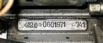
Let's start the review from the rear of the tractor. Just above the fuel filler neck, under the glass, there is a tractor nameplate (nameplate, nameplate). It indicates: 1. Individual serial number of the tractor (VIN, WIN) 2. Engine serial number 3. Tractor model 4. Weight 5. Year of manufacture
A little higher and to the right of the PTO shaft, the transmission number is marked on the rear axle housing (not to be confused with the gearbox number)
Let's move to the right side of the tractor in the direction of travel.
The individual serial number of the tractor is duplicated on the front part of the right side member of the semi-frame, so if for some reason you do not have a nameplate, you can check it using this number. The engine (diesel) number is also duplicated; it is printed on the diesel nameplate, which is attached to the cylinder block on the right, to the right of the oil filler neck.
On the front of the tractor, or rather on the front axle housing, there is the front axle number. If you have a regular portal axle, then you should look for the number on the right sleeve in front of the FDA. If the bridge is beam, then the number is located on the left sleeve in front.
Let's move to the left side of the tractor in the direction of travel (Where the operator usually sits). Here, just above the gearbox dipstick, the gearbox number is located. The clutch number (if necessary) can be found on the clutch housing on the left.
Let's finish reviewing the numbers of components in the tractor cabin. To the left of the operator, closer to the rear axle, there is a nameplate with the cab serial number.
Tip: when checking numbers, they are often under a layer of paint and it is not always possible to see them, especially in low light conditions, so arm yourself with a wide flat-head screwdriver and, if necessary, remove the layer of paint.
Numbers of components of the MTZ-826 tractor
Tractor nameplate indicating the serial numbers of the tractor and diesel engine.
The tractor serial number is duplicated on the front part of the right side member of the semi-frame (or on the right plate of the front ballast weights).
Diesel number (duplicated on the diesel nameplate attached to the cylinder block on the right).
Clutch housing number (on the clutch housing on the left). Gearbox number (on the gearbox housing on the left)
Transmission number for a tractor with a hydraulic lift (on the rear axle housing in the junction area with the gearbox on the right).
Front drive axle number (on the front of the body).
Number of the front drive axle if the FDA is 822 (on the right arm in front of the FDA).
Cab serial number and EC certificate number (inside the cab on the left).
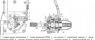
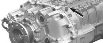
Design, diagram, malfunctions and repair of the MTZ 82 transfer case
The transmission of the MTZ 82 tractor with all-wheel drive chassis is distinguished by a gearbox that provides additional torque distribution for driving the front axle. The unit is attached by its body to the right hatch of the tractor gearbox housing and is called a transfer case. The mechanism can supply power to the FDA in automatic and forced modes with the ability to completely disable the front axle drive.
Dispenser device
The unit is made in a separate cast iron housing in the form of a single-stage gearbox with spur gears and an overrunning clutch. The mechanism receives its drive from the secondary shaft of the gearbox through an intermediate gear mounted on an axis in the gearbox bulkhead. The mechanism is lubricated by spraying oil from the general capacity of the tractor transmission.
The mechanism includes:
- shaft rotating on two ball bearings
- single-acting overrunning roller freewheel clutch, consisting of outer and inner races
- gear coupling with a sliding block for selecting the FDA operating mode
- a control mechanism that allows you to disable - enable and block the freewheel
Overrunning clutch
The outer race 5, being the leading part of the coupling, with its outer ring gear is constantly in mesh with the intermediate gear 12 in the gearbox and receives rotation in all gears. The cage rests on two bearings 7 mounted on the outer diameter of the driven part 6 of the coupling, which, in turn, rotates independently on the transfer case shaft 8, resting on a brass bushing. Thus, both clips rotate independently of each other when unlocked. In eight profile grooves 10 of the leading part of the coupling there are locking rollers with pins 9 and springs 11, which are locked with plugs. To connect to gear block 2 when switching FDA operating modes, the driving and driven parts of the coupling have internal gear rims.
For reference! MTZ 82 transfer case bearing numbers:
- a 306K5 ball bearing is installed on the shaft on the flange shank side
- on the shaft of the reverse side of the unit - ball bearing 305A
- a pair of identical ball bearings between the driven and driving parts of the overrunning mechanism - 115K5
- a pair of tapered roller bearings 7306A on the axis of rotation of the intermediate gear of the transfer case drive in the gearbox
Mode shift clutch
The gear coupling is a single gear block sliding along the shaft splines with external gears of the same name to interact with the driven and driving races of the overrunning clutch. The choice of block position determines the operating mode of the front axle. The control mechanism is a system of rods from the control lever connected to an axis in the unit body, which moves the fork interacting through an annular groove in the gear block.
For reference! The MTZ 52 transfer case differs from the MTZ 82 tractor unit in the absence of a freewheel shutdown mode. The MTZ 82 transfer case can be installed on the 52nd - on the contrary, it is not recommended.
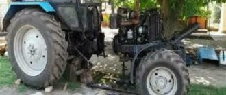
Beam bridge structure
The fundamental difference between the design of this bridge and the portal unit is a different final drive device. The side parts of the beam FDA are gearboxes with pairs of cylindrical gears that transmit rotation from the axle shafts to the planetary wheel drive mechanism with cylindrical gears.
Beam FDA MTZ 82.2 assembled (822-2300020-04)
In the factory catalog, the beam bridge assembly for MTZ 82 is marked under the numbers - 822-2300020-02 or 822-2300020-04 . Separate final drive gearboxes: 822-2308005 - left gearbox, 822-2308005-01 - right gearbox.
Main gearbox and differential
The main gear of the main gearbox and the differential have the same design as in the portal axle. The main pair of gears is a bevel gear with helical teeth. The drive gear is placed on bearings in a separate cast cup, which is attached with its flange to the main drive housing of the bridge. The driven gear is mounted with its internal splines on the differential housing.
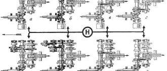
Scheme of beam FDA MTZ
The differential is a self-locking, closed type, with four cylindrical conical satellites located in pairs on two separate floating axles. Automatic blocking is carried out by friction clutches as part of the unit when transmitting force from the lagging wheel. the gears are in constant mesh with the differential pinions. The axle shafts receive rotation through their splined ends, which mesh with the internal splines of the axle gears.
Detailing of beam FDA MTZ 82
To ensure tightness and prevent oil leakage from the cavities of the assembly, cuffs and rubber rings are installed in the sleeves and in the drive gear housing. To eliminate oil pressure, an oil sump ring is installed in front of the drive gear oil seal, at its splined end. The main gear housing is equipped with a breather that ensures optimal pressure inside the cavity.
Final drive final drives
Wheel reducers are attached to the outer ends of the left and right sleeves of the axle axles through two vertically placed axles of the steering axle, each of which is mounted on a tapered roller bearing. The angle of rotation of the gearbox on the trunnion is adjusted by a limiting bolt with a lock nut screwed into the body of the unit.
The final drive drive gear is connected to the axle shaft by a double articulation joint (double cardan joint), which ensures transmission of rotation during cornering conditions. The drive gear rotates with its axis on two tapered roller bearings.
Next, the gear transmits rotation to a cylindrical gear unit that rotates on the hub shaft using a double-row tapered roller bearing mounted with its inner diameter on the splineless part of the shaft. The large ring gear of the block (closer to the axis of movement of the tractor) performs the function of a driven gear, a pair of gears that receive rotation from the axle shaft of the bridge. The small crown of the block is the drive - the sun gear of the planetary part of the gearbox, along the ring gear of which the satellites are rolled.
The planetary carrier with its hub is firmly seated on the splines of the hub shaft, on the outer edge of which there is a flange for mounting the wheel. The shaft itself rotates on two tapered roller bearings: the outer edge of the hub shaft rests on a bearing in the gearbox cover; the inner edge is on the bearing in the bore of the gearbox housing.
Detailing of the side beam FDA MTZ 82
Driven by the sun gear and the satellites rotating in their axes, they simultaneously roll along the internal teeth of the rim of a static fixed gear (epicycle), which is mounted with its outer diameter on the locking pins inside the wheel gearbox cover. Thus, the satellites, pushing off the teeth of the static gear, transmit rotation with an increase in power to the carrier hub. The hub shaft, connected to the carrier through splines, receives rotation and provides direct drive from its outer connecting flange to the wheel.
Operating modes
On an ongoing basis, on dirt roads in rural areas, they use the automatic mode of operation of the front axle. To reduce the wear of assembly parts in field work conditions as part of land-cultivating units - plowing, cultivation, it is advisable to use the forced operating mode of the FDA. In conditions of constant driving on roads with hard, dry surfaces, it is recommended to disable the front axle drive.
Front axle control
The control lever is located on the right side of the driver's seat and is connected to a rod passing through the cabin floor. The control handle has three positions:
- medium - automatic mode is enabled
- lower - front axle is turned off
- upper — FDA is engaged in forced mode
In later versions of the tractor, control is carried out by a lever, in older versions by changing the position of the handle.
Automatic switching on
In automatic mode, the transfer case transmits rotation only when slipping of the rear drive wheels occurs. In this case, by selecting the position of the control lever, the block sliding along the shaft splines engages its smaller ring gear only with the driven race of the overrunning clutch. This ensures that both parts of the overrunning clutch rotate independently in the unlocked position. The power transmission is switched on due to the jamming of the rollers in the grooves and the connection of both cages when the speed of rotation of the driven cage of the mechanism slows down relative to the speed of the constantly rotating driving part of the transfer case clutch.
The gear ratios of the mechanism are designed so that the driven race of the roller clutch, receiving rotation from the passive rolling of the front wheels of the tractor, rotates 6% faster than the driving race of the mechanism. Thus, during standard tractor movement, the clutch does not engage and torque is not transmitted to the front axle from the gearbox. When the movement of the front wheels naturally slows down as a result of slipping of the rear drive wheels, the rotation speed transmitted to the driven race of the overrunning mechanism decreases, but the speed of the drive gear remains unchanged. At the moment the rotation speeds of both parts of the mechanism are equalized, the rollers enter the wedge grooves, causing the parts to rotate as one whole. From the moment of actuation, power is transferred to the wheels of the front axle of the tractor until the rear wheels stop slipping. When the rotation speed of the driven cage increases due to the reverse rotation received from the front wheels, the rollers will come out of the grooves and the clutch will automatically disengage.
Forced mode
It is activated by introducing the engagement of the toothed sliding block with both the inner gear rims of the outer drive and inner driven races of the overrunning clutch. By connecting the three parts of the mechanism, a single rigid block is formed, which receives rotation from the intermediate gear in the gearbox with subsequent transmission through the flanged shank of the transfer shaft to the FDA cardan drive. This inclusion ensures constant power transfer to the front axle.
Disabling FDA
When selecting a position where the gear block disengages from both rims of the two parts of the overrunning clutch, the FDA drive is completely disconnected. In this case, the driving and driven parts of the overrunning mechanism and the gear block rotate independently of each other, that is, the automatic and forced modes are disabled.
Do not register until 16
All this is spelled out in the registration procedure for tractors and self-propelled vehicles, which is approved by government decree. The Subcommittee on Improving the Control and Permitting Functions of Federal Executive Bodies under the Government Commission for Administrative Reform supported the draft of this document.
Let us remind you that on January 1, 2022, the law on vehicle registration came into force. Chairman of the Board of the Association of Lawyers of Russia Vladimir Gruzdev recalled that, according to Article 28 of this law, decisions regarding the state registration of self-propelled vehicles, trailers and other types of equipment are taken by the state authorities of the constituent entities of the Russian Federation. The procedure for such registration is established by the government. This required a new government decree.
In accordance with this document, all such equipment must be registered with the regional bodies of Gostekhnadzor. Nothing has changed here.
But by analogy with ordinary cars, when the document comes into force, it will not be possible to register a tractor or snowmobile for a minor under 16 years of age. If he owns such equipment, then it must be registered with one of the parents or a guardian.
This was done because those who have not reached 16 years of age cannot bear administrative responsibility. Many irresponsible citizens took advantage of this by registering cars and tractors in the name of minors. But for cars this possibility was stopped starting on January 1, and for tractors and self-propelled guns - only from the moment this resolution came into force.
The second important point has also been changed by analogy with conventional cars. You can only register a snowmobile or tractor for one person. Even if, according to documents, this self-propelled gun belongs to several people, only one owner will be indicated in the registration documents. This is so that in the event of any violation it is clear who to file claims against.
It is difficult to imagine that in forests, fields and other habitats of this equipment, compliance with the rules is monitored by cameras that automatically fine the owner of the equipment. But we can assume that the tractor can be used in the city, and its driver can break the rules. Do not exceed the speed limit, but turn around in the wrong place or move in the opposite direction without good reason.
But it was not possible to achieve complete extraterritorial registration of this equipment by analogy with cars. It can be registered at the place of residence, regardless of the place of registration of the owner within the same region. This is due to the fact that Gostekhnadzor bodies are regional.
Third important point. The document clearly states what equipment needs to be registered with the Gostekhnadzor authorities. Let us remind you that, according to the current wording of Article 28 of the registration law, it is necessary to register self-propelled vehicles and other types of equipment and trailers for them, provided that they have an engine. It doesn’t matter what power this engine has. That is, it would be necessary to register bicycles with a suspended engine, self-propelled lawn mowers, children's electric cars, unicycles and all garden equipment that can move.
The government has already submitted a bill to the State Duma that will amend this article. The draft government resolution takes these amendments into account. The document establishes the obligation to register only those self-propelled vehicles for which passports and electronic passports of self-propelled vehicles are issued.
That is, those equipped with an internal combustion engine with a displacement of more than 50 cubic meters. cm or an electric motor with a power of more than 4 kW. These are tractors, self-propelled road construction, utility, agricultural vehicles and other ground-based trackless mechanical vehicles and trailers for them. With the exception of those intended for driving on public roads, motor vehicles with a maximum design speed of more than 50 km/h.
At the same time, other self-propelled vehicles include motor vehicles that have a maximum design speed of 50 km/h or less or are not intended for driving on public roads. Separately, the document stipulates that racing cars, motorcycles, walk-behind tractors, as well as vehicles assembled individually from spare parts and assemblies are not subject to registration with the Gostekhnadzor authorities. Depending on the purpose of the equipment, registration plates of different types will be issued.
Type 3: registration plates for tractors, self-propelled, road construction and other machines. Type 4A: registration plates for off-road motor vehicles not intended for driving on public roads. The document will come into force three months after its official publication.
Maintenance, troubleshooting and repairs
Maintenance of the unit is carried out with general maintenance of the tractor transmission, which consists of checking the tightness of all joints of the system housings and monitoring the oil level. Seasonal oil changes are carried out with a lubricant of the appropriate viscosity when the temperature drops below +5°C. The viscosity indicator is important for the trouble-free operation of the automatic switching mode, since when the temperature drops, thickened summer oil will interfere with the operation of the overrunning mechanism of the transfer case.
Automatic mode does not work
The causes of this problem may be contamination of the running channels of the profile grooves of the gear with dirt and metal oxidation products. And also due to shrinkage of the mechanism springs, unacceptable wear of the rollers and running channels with grooves, and wear-out of the driven part of the coupling.
Often the cause of failures is the appearance of edges on worn rollers. In this case, they are replaced with rollers with an increased repair size to compensate for the increased worn jamming grooves of the mechanism. The first set of rollers have a diameter of 15 -0.012 mm, the repair rollers have a diameter of 15.15 -0.012 mm.
FDA drive does not work
The main cause of the problem is the appearance of unacceptable axial play as a result of wear of the bearings, as well as the bushing on which the driven part of the coupling is mounted. Axial vibration disengages the forced engagement gear coupling, preventing rotation from being transmitted to the drive. To eliminate it, the unit is dismantled, completely disassembled, troubleshooting and replacement of failed parts is carried out.
An additional reason for poor activation of modes is a violation of the adjustment of the switching mechanism as a result of shrinkage of the shock absorbers in the cab mount and a slight change in its position relative to the tractor frame. The unstable position of the fixing post and rod disrupts the amplitude of travel of the levers of the activation mechanism. For normal operation, it is periodically necessary to check the compliance of the positions of the switching modes and make adjustments by changing the length of the rod using a threaded coupling.
Often, malfunctions in the operation of the transfer case occur as a result of a complex of reasons - general wear and contamination of the mechanism, incorrect adjustment of the activation mechanism. If we talk about disruption of the rotation transmission from the transfer case to the FDA, you need to pay attention to the adjustment and technical condition of the intermediate drive support.
In conclusion, it should be noted that the working life and normal operation of the unit are directly affected by the condition of the joints of the cardan drive, the intermediate drive support, and the final drive of the front axle. If unacceptable axial clearances appear in the rotation bearings of the FDA drive units, axial runout will break the bearings in the shaft supports and the transfer case coupling, which will lead to axial instability of the unit parts and, as a consequence, to the impossibility of switching on the drive operating modes or complete failure. Therefore, when repairing any FDA drive unit, pay attention and check the technical condition of all parts, starting with the FDA main drive and ending with the transfer case. This will extend the service life of all drive components and parts, have a positive effect on technical readiness for work, and reduce the cost of maintaining the tractor.
Bridge adjustments and maintenance
Adjusting the clearances in the meshing of gear pairs and rotation bearings in accordance with the technical parameters established by the manufacturer ensures a comfortable operating mode of the mechanisms with maximum preservation of the operating life of the unit.
Kingpin Adjustment
- The main gear is adjusted in the same way as with a portal axle. The tension in the bearings is adjusted by tightening the drive gear shank nut and adjusting washers. The lateral clearance in the meshing of the main gear gears should be 0.18... 0.46 mm. It is adjusted by spacers between the drive gear housing flange and the bridge housing, as well as between the left and right sleeves and the bridge housing. The correctness of the adjustment is checked by the moment of resistance to rotation of the gear, which should be within 0.12...0.18 kgf (1.2...1.8 N.m)
- The tension in the bearings of the final drive pivot pin is set within 0.01...0.1 mm and is adjusted by selecting gaskets 4 under cover 3 in the upper pivot pin support. The cover is removed using the dismantling bolt 1 . In this case, the tension in the bearing must correspond to the force applied to the wheel mounting flange for turning within 6...8 kgf.m (60..80 N.m). During installation, the bearing cover is evenly tightened with mounting bolts 2 with a torque of 12…14 kgf.m (120…140 Nm).
- Adjustment of bearings 3 and 5 of rotation of the hub shaft 4 of the final drive is carried out by tightening nut 1 , with the gearbox removed, at the inner end of the shaft with a force of 18...20 kgf.m. Then unscrew the nut 15-20° and fix its position with a center punch. According to technical requirements, during assembly, the preload in the bearings should be 0.01...0.1 mm.
- The nuts securing the road wheels to the gearbox flange are tightened with a force of 20..25 kgf.m (200...250 N.m)
Lubricating the beam FDA
The kingpin is lubricated in 4-6 injections with a syringe every 125 hours of tractor operation. The oil level to the edge of the filler hole in the axle housing and wheel gear housings is checked every 500 hours of operation. The filling volume of the planetary wheel reducer is 2 liters, the volume of the main gear housing is 3.7 liters. The tightness of all connecting flanges of the axle parts and the drive mechanism is checked every 1000 hours of tractor operation. (the slides indicate: arrow - control filler plugs, numbers - drain plugs of units)
Monitoring the lubricant level in the final drive gearbox of the beam FDA
Checking the oil level in the FDA housing
Checking the oil level in the intermediate support of the FDA drive
Options for equipping MTZ 82 tires with a beam axle
An important factor is compliance with the dimensions of the rear and front tires of the drive axles established by the manufacturer. Inappropriate configuration leads to a change in the final drive gear ratio of the front and rear axles, which will disrupt the synchronization of the torque supply. The lag of one of the axles from the other directly affects the driving performance of the tractor, and also leads to unwanted loads in the drive mechanisms and the FDA mechanism.
- For front tires 360/70 R24 - rear tires 18.4R34 or 15.5R38
- When installing front tires 13.2-20, install rear tires 16.9R30
- With front tires 9.5-42 - install rear tires 11.2R24
In conclusion, it should also be noted that often, if they want to equip a tractor with a beam front axle, tractor drivers purchase units from machines of other traction classes - MTZ 1221, 1523. This initiative also leads to similar disruptions in the operation of the transmission and chassis due to the discrepancy between the gear ratios of the gearboxes of the installed unit, despite the same design.
PVM drive MTZ-82
The front drive axle of the FDA of all-wheel drive tractors MTZ-82, MTZ-82.1 with a gearbox switched by moving gears is driven through a transfer case and a series-connected intermediate cardan shaft, an intermediate support with a safety clutch and a front cardan shaft.
On tractors with a powershift or synchromesh transmission, the front axle is driven directly from the transmission by a torsion shaft located in the transmission and clutch housings and a single driveshaft located externally. In this case, the friction clutch for engaging the front axle is also a safety clutch.
The transfer case is used to transmit torque from the gearbox to the front drive axle. With its help, the front axle is automatically or forcefully turned on and off.
The MTZ-82, MTZ-82.1 FDA drive with a power shift gearbox and a synchronized gearbox is mounted in the gearbox housing.
The front axle is turned on and off by the PMG both automatically and forcibly. Automatic activation (disengagement) - using a freewheel mechanism (depending on the slipping of the rear wheels) only for moving the tractor forward, forced activation (disengagement) - both when moving forward and when moving backward.
The cardan transmission consists of two cardan shafts of the same design and length (rear and front).
The cardan shaft of the MTZ-82 tractor has cardan joints on needle bearings. The central part of the shaft is made of thin-walled pipe 1 (Fig. 1) into which forks are pressed at both ends and welded to it.
Rice. 1. Cardan drive of the front drive axle (FDA) of the MTZ-82.1, MTZ-82 tractor with an intermediate support
1 — cardan shaft; 2 — needle bearing; 3 - retaining ring; 4 — crosspiece oil seal assembly; 5 — driveshaft oil seal reflector; 6 — grease fitting; 7 — crosspiece: 8 — cardan flange; 9 - gasket; 10 - bearing; 11 — pressure disk; 12 — driven disk; 13 - drive disk; 14 — spacer sleeve: 15 — intermediate support shaft; 16 — sliding flange; 17 — sealing rings; 18 — cuff body; 19 — cuffs; 20 — coupling bushing; 21 — intermediate support body; 22 — disc springs; 23 — support washer; 24 — connecting flange of the cardan shaft: 25 — nut; 26 - oil deflector washer.
Each cardan shaft of the MTZ-82 tractor is dynamically balanced; to eliminate imbalance in areas with less mass, metal balancing plates are welded to the edges of the shaft.
Uneven rotation of the cardans, as well as imbalance, causes pulsating loads in the joints and transmission.
To reduce uneven rotation, the forks are welded to the shaft pipe so that the axes of the holes for the bearings in the forks are located in the same plane.
On a gearbox switched by moving gears, the MTZ-82 intermediate and front cardan, connecting, respectively, the transfer case and the intermediate support, the intermediate support and the main gear of the front axle, are identical and interchangeable.
On tractors with a power shift transmission and a synchronized transmission, the cardan shaft differs in the length of the shaft tube and one outer (sliding) yoke. The sliding fork 15 rotates on sliding bearings (bushings), which are pressed into the bore of the clutch housing.
The universal joints of the MTZ-82 tractor and the fork (except for the sliding one) are interchangeable with similar parts of UAZ vehicles.
Compensation for changes in the distance between the connecting flange of the main drive and the sliding flange 16 (see Fig. 1) of the intermediate support, caused by the swing of the front axle in the eyes of the half-frame beam, is ensured by axial movements of the sliding and connecting flanges of the intermediate support inside the connecting sleeve.
The cardan drive guard is used to prevent straw crops from wrapping around the front axle driveshaft hinges when performing harvesting work.
The removable casing of the intermediate propeller shaft guard is attached on one side with two bolts to the cuff body of the transfer case connecting flange, on the other - with a clamp to the intermediate support body.
The front driveshaft of the MTZ-82 tractor is protected by two removable covers. The rear casing is bolted to the intermediate support housing, and the front casing is bolted to the flange of the main gear housing.
If the tractor is not used for work, when it is possible to reel in straw crops using cardan joints, then the fence must be dismantled (you should not work with the fence unnecessarily due to the difficulty of maintaining the cardan drive).
The intermediate support of the MTZ-82 tractor with cardan transmission is a bearing unit with a tubular splined sleeve in which the intermediate and front driveshafts are telescopically connected by means of connecting 24 and sliding 16 flanges, respectively.
The cast-iron body 21 of the intermediate support, made as one piece with the bracket, is installed on the clutch body from below on two pins and is bolted to it. A friction multi-disc safety clutch is located inside the housing.
The safety clutch limits the torque supplied to the front axle in cases of overload, and thereby prevents damage to the shafts and gears of the MTZ-82 front axle drive.
The rotation of the intermediate cardan shaft is transmitted through the connecting flange 24 to the shaft 15 of the safety clutch.
Drive disks 13 (16 pcs.) are connected to the splines of the shaft 15 and, due to friction, transmit torque to the driven disks 12 (15 pcs.), which are connected to the splines of the connecting sleeve 20.
With the same splines, the sleeve 20 is telescopically connected to the sliding flange 16, from which rotation is transmitted through the front driveshaft to the main gear of the front axle.
When the safety clutch slips, the flange 24 and the intermediate driveshaft of the axle drive connected to the transfer case rotate at a higher frequency than the sliding flange 16 and the front driveshaft connected to the drive gear of the final drive, i.e. the intermediate propeller shaft rotates relative to the front propeller shaft and the intermediate support shaft 15 rotates relative to the sliding flange 16.
When operating without slipping of the clutch, all parts located inside the connecting sleeve 20 rotate as one unit with the sleeve 20 in two ball bearings 10.
The friction discs of the safety clutch are compressed by the force of three pairs of disc springs 22, which are tightened through the connecting flange 24 with a nut 25. To supply lubricant to the friction discs, holes are drilled around the circumference of the connecting sleeve 20.
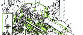
Design and diagram of the MTZ-82 front axle
We will study this mechanism in full, but first we need to fully understand the circuit and devices of this mechanism. To do this, we present its complete diagram and give a breakdown of the details.
The main task of the front axle of the Belarus MTZ-82 tractor is to transmit torque from the engine to the steering front wheels. The mechanism itself consists of: transmission, front differential and wheel gearbox.
The transmission design is made of two bevel gears with spiral teeth. The drive gear (37) is placed on a tapered roller bearing (40) in the cup (39). The driven one (25) fits into the belt of the differential housing (27) and the splines, using a nut (24) it is secured against any axial movements.
Front drive axle differential
This mechanism uses a limited-slip self-locking differential. The cover (31) and the body (27) are connected by bolts; they contain semi-axial gears (21), a satellite (30, driven (36) and driving (28) friction discs. As well as pressure cups (35).
The differential integrally secures two axle shafts, eliminates separate wheel slipping and significantly increases the traction force of the tractor. When it is turned on, the wheels lock. Reinforcement from the axles passes to the satellites, which is transmitted by the shoulder cups (35). In turn, this causes the friction discs (26 and 36) to compress.
The differential is locked using friction.
If the friction force in the discs (26 and 28) exceeds the standard deviation at the moment of rotation, then slippage occurs. The MTZ-82 front axle differential is placed in the cover (20) and housing (34) on tapered roller bearings (32).
Additionally, a breather (33) is installed in the system, which maintains normal pressure in the differential cavity.
How is the front axle of a tractor connected?
With the help of hollow axles (58) and a beam, the bridge is connected, in turn, the hollow axles ensure the rolling of the front wheels and the bridge in the transverse plane. The axes are stopped from moving using bars (59).
Mechanical final drive gearboxes are installed in the sleeves of the cover (20) and the solid body (34). They consist of pairs of bevel gears, which serve as joints of equal angular velocities.
Splined shanks with gears secure the differential axle shaft and vertical shaft. The tractor axle shaft itself is mounted on two tapered roller bearings (14), and the vertical shaft rests on them and its installation takes place in the bore of the pivot pipe (13). The cuffs (16 and 45) together with the paronite gasket seal the cavity (19) along cover surface.
The pivot pipe (13) is supported by a coiled coil spring (49). The pipe itself fits into the sleeve (47); it is also pressed into the gear housing (53) and secured with a pin.
How is torque transmitted?
The process itself is quite simple to understand; first, the disc flange (2) rotates on a roller-type bearing (50) and a pair of conical bearings (4), which are pressed into a glass (6), which is located in the bore of the cover (1).
The gear (52) and bearing are secured with two bolts and a washer from moving along the axis. The lower conical pair is sealed using a rubber ring, which is placed in the glass (6), as well as a lip and paronite gasket along the plane of the housing cover (53). A swing arm with trapezoid steering rods and a bracket for the wheel fenders is attached to the gear housing. Torque is transmitted to the disc flange (2) from the differential axle gear (21), using the gear of the lower and upper bevel pair.
Repair of the front drive axle MTZ-82
We will consider the repair in several stages depending on those symptoms. Which can be observed. Each stage will be illustrated with detailed pictures.
If traces of grease appear on the propeller shaft flange and the main gear housing, this is the first sign that elasticity will be lost and the main gear cuff will collapse. To do this, replace the cuffs and disconnect the driveshaft. First, unscrew the castle nut and remove the cardan flange. Next, unscrew the bolts securing the main gear cup bearings and two mounting bolts. Afterwards, the drive gear is pressed into the glass and the assembly with the cuff itself is removed.
If traces of oil are found on the inner surface of the wheel rim or on the disk flange, this is a sign that the wheel axle is damaged. To do this, you need to remove the wheel and the final drive gearbox as a complete assembly (see the diagram of the arrangement of parts for the final drive gearbox of the MTZ-82 tractor).
then you need to unscrew the two radial bearing securing bolts and remove the driven gear.
So we looked at the main problems of the front axle of the MTZ-82 tractor. We hope that this article was useful to you.