Controls and instruments
Rice. 3a.
1 — diesel engine stop and emergency stop handle. When you pull the handle toward you, the fuel supply to the cylinders stops and the diesel engine stalls. When released, the handle returns to its original position under the influence of a spring.
2 — control handle for the cabin heater valve (if installed).
3 — differential lock control handle (for tractors with power steering housing); has three provisions:
- I "lock off"
- II "automatic blocking",
- III “forced blocking”.
4 — handwheel for controlling the water radiator shutter. When the handwheel rotates clockwise, the curtain rises; when rotated counterclockwise, it lowers. When the curtain is lowered, the temperature of the diesel engine decreases.
5 — rear axle differential lock pedal. When you press the pedal all the way, the lock is turned on, when you remove your foot from the pedal, it turns off.
6 - switch for starting aids (EFS).
7 — windshield washer switch.
8 - light switch. It has two positions: I — instrument lighting and side lights are on; II - in addition to position I, road headlights are turned on.
9 — alarm switch.
17 - switch for direction indicators, low and high beams, sound signal.
19 — radio receiver (optional).
20 — cover of the steering wheel height adjustment mechanism. To change the height, remove the cover, unscrew the wing nut 3-5 turns and set the required steering wheel height.
21 — front window wiper switch.
22 — cabin heater fan switch.
23 - switch for rear working lights.
24 - front working headlight switch.
24a — switch for the “Road Train” sign.
25 — cabin lamp with switch.
26 — air distributor of the cabin ventilation and heating system.
Rice. 3b.
Important ! Before you start working on the tractor, study the purpose of the controls, instruments and their functions.
27, 28, 29 — hydraulic system distributor control levers: 27 — left side terminals; 28 — right side terminals; 29 - rear terminals. If the tractor does not have a power regulator, then lever 29 controls the cylinder of the hitch, and lever 27 controls the left side and rear outputs duplicated with it.
The connection diagram for the hydraulic system terminals is shown on the instruction plate in the tractor cabin (see Fig. 4.1). Each lever has 4 positions: “floating”, “forced lowering”, “neutral”, “raising”. In the “forced lowering” position with the engine running, the lever should be held by hand.
Rice. 4.1.
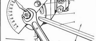
30 — tachometer speedometer control panel (see Fig. 9.2).
31 - starter and instrument switch. Has three positions (from neutral):
- I - power supply of devices;
- II - turning on the starter;
- position counterclockwise from neutral - the radio is on.
32 — lever for turning on the reduction gear. It has two positions: front - “Gearbox on” (slow movement of the tractor) and rear - “Gearbox off” (fast movement of the tractor).
In a tractor with a synchronized reduction gearbox, the control lever 32 has two positions: rear - “Gearbox on” (slow movement of the tractor) and front - “Gearbox off” (accelerated movement of the tractor).
In a tractor with a synchronized reverse gearbox, control lever 32a (Fig. 4.1.1) (unlike lever 32 is bent to the left along the tractor) has two positions: rear - “Reverse on” and front - “Reverse off” (forward travel) .
Rice. 4.1.1.
33 — connecting bar of the brake pedals for simultaneous braking with the right and left brakes.
34 — fuel control pedal.
35, 36 — brake pedals. When you press the pedals with your foot, the tractor slows down; at the same time, the brake valve of the pneumatic drive of the trailer brakes is activated from pedal 35. 37 — handle for fixing the tilt of the steering column.
38— clutch control pedal.
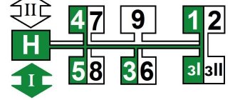
39 — gear shift lever. When moving the lever forward in the extreme left position, the 2nd (increased) gear range is switched on, and back - the 1st (lower) gear range. Gear shifting is carried out in accordance with the diagram (Fig. 4.2.).
Rice. 4.2.
40 — control lever for the attachment fixing mechanism. The extreme left position of the lever is “the hitch is fixed”, the extreme right is “the fixation is removed”. You must first raise the hitch to the top position.
41 — control lever for the transfer case of the FDA drive. The middle position of the lever is “FDR is switched on automatically”, lower (pull) – “FDR is switched off”, upper (pull) – “FDR is forcibly switched on”.
42 — parking brake control lever.
43 — lock of the power regulator control handle.
44 — fuel supply control handle. The extreme forward position is the maximum fuel supply, the rearmost position is the minimum supply corresponding to the minimum idle speed.
45 — power regulator control handle. The rearmost position of the handle is “raising the implement” (while lifting, hold the handle with your hand); after releasing the handle, it moves forward and is fixed in the “transport neutral” position. The intermediate position forward from the “transport neutral” position is the “regulatory zone”. The extreme forward position of the handle is “forced lowering” (hold the handle with your hand). After releasing the handle, it returns back and is fixed at the leading edge of the control zone.
46 — rear PTO control lever.
It has two positions: front - “PTO off”, rear - “PTO on”.
47 - battery ground switch.
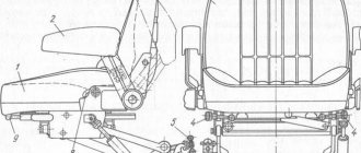
48 — seat backrest tilt lock.
49 — seat belt bolt
Gearbox design MTZ-80 and MTZ-82
The MTZ-80/82 gearbox is a cast-iron crankcase containing 4 shafts on which gears are mounted. The main shafts are the primary and secondary, which are located one above the other. When generating torque, they are helped by two other shafts - intermediate and additional.
All gearbox shafts rest on bearings located in the walls of the box housing, as well as in the central partition.
The gearbox housing itself is filled with transmission oil, which provides lubrication of the rubbing surfaces. To prevent oil from leaving the crankcase, there are seals at the ends of the shafts.
Photo of MTZ-80/82 gearbox
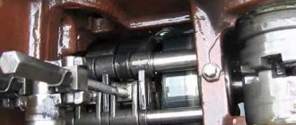
Design of the reverse gearbox MTZ-80 and MTZ-82
A reverse gearbox is located between the clutch housing and the gearbox. This unit is responsible for quickly changing the direction of movement from front to rear.
The reverse gearbox consists of two units: a block of shafts and gears, as well as a gearbox control unit. A drawing of the reverse gearbox can be seen in the figure below:
The numbers in the figure indicate:
- reverse gear cover;
- synchronizer;
- lever;
- roller with fork;
- retainer ball;
- cup;
- sleeve;
- gearbox input shaft;
- driven gear;
- Transmission;
- front socket;
- clutch housing;
- idler gear;
- satellite axis;
- pin;
- satellite;
- ball bearing;
- power shaft;
- drive gear;
- lid;
- parallelogram mechanism;
- reverse gear control lever.
Popular unit modifications
As is the case with many popular tractors, the MTZ-80 received several modifications that were intended for certain jobs. The most famous of them include:
- MTZ-80.1 - an enlarged cabin and improved rear-wheel drive made this tractor popular among owners of land located on slopes. This model had reliable spare parts and a modernized gearbox. It made it possible to operate the tractor without any preparation for work;
- MTZ-80L is a tractor designed for forestry work. It was used mainly to fight fires and restore forests. This unit was equipped with a diesel engine with a power of 60 hp. With. Among the disadvantages is the need for frequent repairs of the chassis.
Each of these representatives is still popular, because, at a low cost, these machines have high reliability and excellent performance.
Primary shaft
The input shaft is one of the most important parts of the gearbox. It is through the clutch that the torque from the engine enters the gearbox. One side of the input shaft interacts with the clutch basket. The other side transmits torque to the secondary shaft coupling.
The primary shaft in the box rests on two bearings and has gears on it, which are responsible for turning on the 3rd, 4th, and 5th speeds of the tractor.
Another important function of the input shaft is to transmit rotation to the speed reducer. It is connected to it through a gear drive.
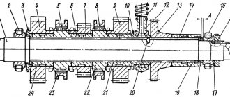
Operating procedure for the MTZ-80 and MTZ-82 gearboxes
The figure above shows a diagram of the MTZ-80/82 gearbox. It will be needed to understand how the checkpoint operates.
Torque from the engine, through the clutch, is transmitted to the input shaft, which is designated by the number 1. There are two gears on the shaft (numbers 3 and 4). These gears can move along the shaft; they are responsible for 5, 4, 7, 8 speeds. The order in which these speeds are turned on can also be seen in the figure.
In addition, gear 4, when engaged with gear 5, engages 9th gear.
The intermediate shaft, designated 14, is responsible for transmitting torque to the gearbox secondary shaft, designated 7.
The moving gears on this shaft are marked with the number 18. It is the block of these gears, when moving forward along the shaft, that is responsible for 1, 3, 4, 5, as well as 1 reverse speed. If this block moves backward, then it is responsible for engaging 2, 6, 7, 8 and 2 reverse gears.
The additional shaft, designated 27, is involved in generating the torque of 1st and 2nd forward gears, as well as both reverse speeds.
The secondary shaft (number 7) transmits torque directly to the drive wheels. All transmissions go through intermediate or additional shafts, and only in direct 9th speed 2 shafts are involved: primary (1) and secondary (7).
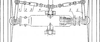
Installation of attachments
The tractor is equipped with a three-point rear linkage design, made according to the classical design. The device consists of 1 central, two longitudinal rods, braces and a power cylinder that raises and lowers attachments.
To manage inventory, the machine is equipped with a separate hydraulic device, which consists of the following parts:
- Gear type oil pump;
- Motor driven;
- Hydraulic distributor with three sections;
- 2 or 3 cylinders.
MTZ-80 is operated with various attachments. For work you can use:
- Kuhn;
- Potato digger;
- Plow;
- Harrow;
- Hiller;
- Kosarka;
- Snow shovel and much more.
If necessary, the tractor can be equipped with a trailer. The design of the machine allows you to connect a generator.
Specifications
Technical characteristics of the MTZ-82 tractor:
| Characteristics | Unit measurements | Indicators |
| Traction class | — | 1,4 |
| Dimensions (LxWxH) | mm | 3930x1970x2740* |
| Ground clearance (minimum) | mm | 470 |
| Engine | type | diesel, 4-cylinder, radn., |
| Working volume | l | 4,75 |
| Power | hp | 80 |
| Starting system | type | Starter(82), Starter(82L) |
| Transmission | type | mechanical |
| Number of gears | PC. | 18-forward, 4-back |
| Drive unit | type | full |
| Speed (min/max) | km/h | 1,3/34,3 |
| Weight | kg | 3770 |
| Fuel consumption | gkWh | 230 |
*- The height indicated is for a tractor with a small cabin.
How to drive a tractor?
Persons who have completed a training course in the direction “Fundamentals of control and traffic safety of tractors” are allowed to operate the tractor.
Before moving on to driving the tractor, a number of preparatory works are carried out:
- Check the serviceability of tractor components;
- Measure tire pressure;
- If there is attachments on the tractor, visually inspect the tow bracket;
- Remove the casing from the tractor power unit to ensure the proper condition of the battery, cooling system and radiator;
- Wear comfortable clothes and shoes, avoiding loose hair and jewelry;
- The driver's seat settings are adjusted to the height and weight of the operator. With your back resting on the seat, your hands should have free access to the tractor controls, and your feet should have free access to the pedals.
The tractor control process occurs as follows:
- They start the engine and begin to move away - the first attempt to move begins with a warm engine. To do this, reduce the fuel supply, turn off the clutch handle, select a working gear, increase fuel consumption and move the clutch pedal to the on mode;
- When the tractor has moved, they begin to accelerate it to the required speed - they reduce the fuel supply, disengage the clutch, set the desired mode on the gearbox, smoothly engaging the clutch;
- To make a turn at the end of acceleration and pull the plow out of the ground, the accelerator is set to minimum feed;
- Controlling the tractor during the first rut - laying the 1st furrow begins with setting a straight trajectory of movement. In flat areas, for this purpose, one pole and a sighting device are used, built into the tractor; for fields with complex geometry, several poles are required that delimit the entire field. On modern tractors, this control issue is solved faster - with the help of GIS technologies;
- When performing the main cycle of work, the tractor driver must constantly “maneuver” between gears – i.e. choose the optimal rhythm of work for a specific agrotechnical task and the characteristics of the cultivated area. So, to move up a slope and on clayey, loamy, gravelly and heavy chernozems, low gears are used, and in the opposite case, high gears;
- Turning and turning on the field is unacceptable with working adapters and at high speed. To turn the tractor on wheeled propellers, reduce the speed to 5 km/h and apply the brakes to the wheel that is in the center of the turning circle. Turning a caterpillar tractor is done only in extreme cases;
- Driving a tractor while going down a slope is an extremely dangerous maneuver, during which the load is shifted from the front wheels to the rear wheels. To perform it without the risk of an accident, reduce the diesel supply, select a low gear and periodically brake the engine;
- In order to drive a tractor with mounted adapters from the PTO without damage to the power plant and with safety for yourself, you must remember to turn off the power take-off when turning and switch them to transport mode - when going uphill. When moving between areas, it is advisable to disconnect the PTO shaft shank from the cardan drive.
These requirements apply to both factory models and homemade tractors from Niva or Oka.
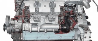
Tractor engine design
The engine of the machine belongs to the class of 4-cylinder, four-stroke engines with a water cooling system for the tractor.
It was created specifically for the line of these tractors at the same Minsk Tractor Plant. The operating volume of the engine is approximately 4.75 liters. Thanks to high-quality electrical equipment and a semi-separate combustion chamber, the rated engine power is 80 hp. s., and torque – 2200 rpm. The weight of the diesel engine is 428 kg. Some tractor models are additionally equipped with a pre-heater PZHB-200B. To start the machine, it is equipped with an electric starter and a carburetor starting motor. The design also includes a starter locking device, which must be used to hold the tractor in place when the engine is running.
To extend the life of the engine, the manufacturer recommends inspecting and servicing it every 240 operating hours. The manufacturer does not recommend using the heater unless necessary, as this negatively affects the stability of engine torque.
Cabin and unit interior
The Belarus MTZ-80 tractor is equipped with a spacious cabin. It is attached to the power frame using rubber shock absorbers, which effectively suppress noise from the operating transmission and tractor engine. The comfortable driver's seat can be adjusted in height.
The internal surfaces of the cabin of the MTZ-80 unit are finished with thermal and noise-absorbing material. There are rubber mats on the floor that prevent the driver's feet from slipping off the pedals. The interior of the tractor cabin will be clearly demonstrated in the photo.