Minsk dump truck: MAZ-503A (Our auto industry): diecast43
While all enlightened humanity is busy discussing sanctions and anti-sanctions, and prudent fellow citizens are lining up for Finnish butter, Italian sausage and French cheeses, collectors are again forced to spend their hard-earned money not on Belgian pate or Polish apples, but on yet another large-scale copies of Soviet trucks made by the Chinese .
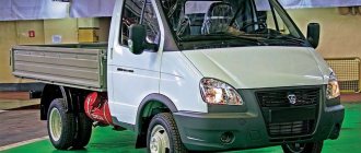
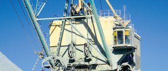
A couple of days ago, Minsk dump trucks in four colors with two different bodies appeared on the shelves of model stores - the promised MAZ-503A saw the light of day. Two exhibition and overhaul colors - red and dark green with black cladding remained in the store, and two trucks with more familiar colors and at least some claim to historical authenticity were put on the shelf - the first of them is a 1970 MAZ-503A with a pale a blue cabin and an unexpectedly green body (I would like, of course, gray).
Collectors are already familiar with the cabin with such a cladding - a scattering of MAZ flatbeds arrived in stores earlier, so all attention is on the body. And this body is the main disappointment: it doesn’t rise, the tailgate doesn’t fold down. This makes it sad and the dump truck loses half of its attractiveness - it won’t be able to dump anything on its own. And against the backdrop of rising prices for truck models in “Our Automotive Industry” boxes, such a nuance in execution completely discourages people from buying the model. Many, of course, will make an effort - there were plenty of Minsk dump trucks on the streets, and even now there are cars with such a cab. Someone will saw through a Chinese product and make the body work, but the rest have two options - put the model on a shelf and sigh, knowing that the body cannot be lifted, or wait for a model from another manufacturer. There is a chance, and sanctions do not yet apply to China.
The model itself is quite decent, similar to the prototype and quite neat - and inexpensive compared to St. Petersburg products:
Car model: 1970 MAZ-503AN Model name: MAZ-503A dump truck (1970) Manufacturer: Hongwell Release date: August 4, 2014 Catalog number: H757 Series: “Our auto industry” Circulation: no data Brief opinion: dump truck layout Subjective assessment: 7/10
A backup copy of the recording is here: https://diecast43.dreamwidth.org/376329.html Journal Navigator
diecast43.livejournal.com
In modern world
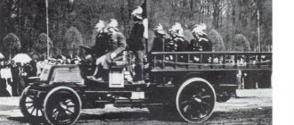
You will no longer find this representative of dump trucks on the market of large-sized equipment. They were relevant and in demand until the 1980s, but then they were supplanted by more progressive trucks created on the basis of the MAZ-5335.
But Soviet-made copies that have survived to this day can be actively used on medium-sized construction sites, in agriculture and in some industrial areas. And every year their number becomes less and less.
Soon the MAZ-503 (a photo of which can be seen in this article) will become only a memory. Those who are interested in the Soviet automobile industry can find a scale (1:43) model of the Kostroma plant.
Dump trucks MAZ-503 and MAZ-503V
Construction machines and equipment, reference book
Category:
Buses and special vehicles
Dump trucks MAZ-503 and MAZ-503V
The MA3-503 dump truck with a lifting capacity of 7 tons is based on the MAZ-500 vehicle and, in comparison with it, has a shortened frame with a reduced wheelbase (3200 mm), an increased rear axle final drive ratio (9.57 instead of 7.73) and a braking system , equipped with a single ZIL type crane without a line to the trailer. The vehicle is additionally equipped with a bucket-type body that tilts back and has a hydraulic lifting system with a pneumatic control drive.
On the MA3-503 car, a metal welded bucket-type body is pivotally connected at the rear to the axle of a subframe mounted on the car frame.
The vehicle can also be equipped with a tipper body with a pneumatically controlled hinged tailgate (model MA3-503B).
The hydraulic lifting system of the MA3-503B vehicle includes a power take-off (Fig. 489), an oil tank with a filter, an oil pump with a discharge valve, a bypass valve, a telescopic lift and oil lines: inlet, discharge and bypass. The entire system is controlled using a pneumatic valve and air diaphragm working chambers of the power take-off and bypass valve, fed by compressed air through air ducts from the brake system cylinders. The pneumatic system of the MA3-503B also includes a tailgate lock control cylinder. The power take-off is single-stage and is attached by a crankcase flange to the gearbox housing on the left side opposite the hatch in it. In this case, the intermediate gear, mounted on the axle on a roller bearing, is in constant engagement with the additional gear of the intermediate shaft of the gearbox. In the power take-off housing, a hollow shaft is mounted on ball bearings, on the splines of which a movable gear can move. The drive gear shaft of a gear oil pump (type NSh-32) is connected to the hollow shaft by splines, the housing of which is attached to the power take-off housing.
The movement of the movable gear to turn on the drive to the pump is carried out by the rod of the pneumatic chamber with a diaphragm loaded with a spring. The rod is connected to the gear shift fork. An air duct from a pneumatic distribution valve is connected to the pneumatic chamber.
Rice. 1. Diagram of the hydraulic tipping system with pneumatic control of the MA3-503B dump truck
The pump's discharge cavity is connected via an oil line to a hydraulic lift and a bypass valve through a discharge valve.
The hydraulic telescopic lift consists of a cylindrical body, inside of which there are three retractable cylinders equipped with sealing devices. The maximum stroke of the retractable cylinders is limited by guide sleeves secured in the links by retaining rings. With axles welded to the body, the lift is pivotally mounted in the bracket supports mounted on the platform subframe. The ball pin, fixed to the head of the inner cylinder, is connected by a nut to the spherical heel of the platform base.
The bypass valve consists of a housing with a valve stem installed in it, which is constantly pressed by a spring to a rubber seat located in the housing cover. A ball safety valve with a spring secured by a plug and a movable spool is installed in the channel of the valve stem. The safety valve limits the maximum pressure in the hydraulic system. The valve stem is connected to the diaphragm of the pneumatic working chamber mounted on the control spool body. In addition, the spool is connected by a cable to a lever mounted on the hydraulic lift body. The required length of the cable is adjusted by a threaded sleeve wrapped in the lever pin.
An oil line from the pump and lifter is connected to the side hole of the bypass valve body. An oil bypass line leading to the tank filter is connected to the hole in the cover. An air duct from a pneumatic distribution valve is connected to the opening of the pneumatic chamber.
Rice. 2. Equipment elements of the hydraulic system for tipping the body of the MA3-503B dump truck: a - bypass valve; b - pneumatic distribution valve
The pneumatic distribution valve is used to remotely control the hydraulic system of the body lifting mechanism. In the cast body of the valve, closed by the upper and lower covers, there is a roller installed, the lower end of which is connected to a rotating spool, pressed to the plane of the body by a disc spring.
At the upper end of the roller there is a gear mounted on a key, with which a sector mounted on the roller engages, at the outer end of which there is a lever connected by a rod to the control handle located on the instrument panel in the cockpit.
In the middle part, a locking disk is attached to the shaft on a key, into the recesses of which a ball can enter under the action of a spring installed under the plug. The plug is wrapped in the body and secured with a lock nut. All tap connections are securely sealed.
The housing has four vertical channels, which, using a spool having one through hole and a blind connecting groove, can be connected to air lines and the atmosphere in different sequences.
An air duct from the air cylinders of the vehicle's brake system is connected to the hole in the bottom cover.
Air ducts from the working chambers of the power take-off and bypass valve are connected to the housing channels. The channel is connected to the atmosphere. The channel on the MA3-503 dump truck is closed with a plug, and on the MA3-503B dump truck, an air duct is connected to this hole, which goes to the pneumatic, double-acting cylinder for controlling the tailgate locks of the platform.
The pneumatic lock control cylinder has a body with covers and a piston with a rod. The covers have holes to which air ducts from the control valve are connected. The cylinder is hinged under the body, and its rod is connected to the lever of the tailgate locking shaft.
The pneumatically controlled hydraulic lifting system works as follows.
When the control valve handle is installed in the neutral position (spool in position I), the working chambers of the power take-off and bypass valves are connected to the atmosphere, so the pump is turned off and the bypass valve is closed, which isolates the lift cylinder from the system and makes it possible to stop the body at the required or completely lowered position position In the upper cavity of the tailgate power cylinder at. In this case, compressed air is supplied, and the side locks are held in the closed position.
When the valve handle is turned to the “Lift” position (spool valve in position II), air enters the working chamber of the power take-off, and the bypass valve chamber is exposed to the atmosphere. In this case, the power take-off is turned on and the pump is running, and the bypass valve is closed. Oil from pump 6 flows through the discharge valve into the lift cylinder, which, expanding, lifts the body.
When the body is fully raised, when the retractable cylinders reach their stop, or when the body is overloaded, the oil pressure in the system increases to 130 kg/cm2. At the same time, the safety valve in the spool opens and oil, entering under the spool, moves it. The spool, resting against the edges of the socket, moves the rod, opening the bypass valve, and excess oil pumped by the pump begins to flow from the pump back into the tank.
When the crane handle is set to lift, compressed air enters the lower cavity of the side cylinder, which opens the tailgate latches.
At the end of the body lift, the lift cylinder lever, deflecting along with it, tightens the cable and opens the bypass valve, as a result of which the pressure in the cylinder drops sharply and the body begins to quickly lower, releasing the cable. At the same time, the valve closes again, and the body begins to rise again until the cable is pulled again. Such a sharp shaking of the body at the end of the lift makes it easier to dump the cargo in the body. When the control valve handle is set to the lowering position (spool in position III), the working chamber of the power take-off is connected to the atmosphere, and the box turns off the pump drive. The air pressure entering the working chamber of the bypass valve keeps it in the open position. In this case, the lift cylinder is connected to the oil bypass line, and the body lowers under its own weight, displacing oil from the lift cylinder through the oil bypass line through the filter back into the tank. The oil discharge line of the pump is closed using a discharge valve. In the side cylinder, its lower cavity communicates with the atmosphere, and compressed air enters the upper cavity, and the side latches are held in the closed position.
The hydraulic lifting system of the MA3-503 works the same way. There is no side cylinder in it.
Read more: BelAZ dump trucks
Category: – Buses and special vehicles
Home → Directory → Articles → Forum
stroy-technics.ru
COMMON DATALoad capacity in kg. 8000 Gross vehicle weight with load in kg. 15250
Weight distribution without load in kg. on the front axle 3580 on the rear axle 3520
Weight distribution with load in kg. on the front axle 5250 on the rear axle 10000
Vehicle base in mm 3400 Rear wheel track (between the centers of the double slopes) in mm 1865 Front wheel track in mm 1970 Ground clearance in mm: to the front axle 270 to the rear axle housing 270
Minimum turning radius in both directions in m along the bumper 8.5 along the front outer wheel track 7.5
| Overhang angles (with full load) in degrees: front 28 rear 48 Overall dimensions in mm: length 5785 width 2500 height (without load) 2650 Body capacity (without additional sides) in cubic meters. 5.1 Highest speed at full load on a horizontal section of a straight road in km/h 75 The braking distance of a vehicle (with a full load without a trailer) moving at a speed of 40 km/h on a horizontal section of a dry road with a hard surface should not exceed 18 m Control fuel consumption per 100 km in l 22 |
ENGINE
Engine model YaMZ-236 Engine type Four-stroke, compression ignition Number of cylinders 6 Cylinder arrangement V-shaped, with a camber angle of 90° Cylinder operating order 1 – 4 – 2 – 5 – 3 – 6 Cylinder diameter in mm 130 Piston stroke in mm 140 Cylinder displacement in l 11.15 Compression ratio 16.5 Rated power in l. s 180 Nominal speed in rpm 2100 Maximum torque in kg-m 68 Rotation speed at maximum torque in rpm 1500, no more Minimum idle speed in rpm 450 - 550 Maximum idle speed under the influence of the regulator in rpm 2225 - 2275 Minimum specific fuel consumption according to the speed characteristic in g/l. With. h 167+5% Method of mixture formation - Direct injection Combustion chamber - Continuous type in the piston
Intake valve timing: opening 20° to i.e. m.t. closing 56° after n. m.t.
exhaust valve: opening 56° BC. m.t. closing 20° after c. m.t.
Number of valves per cylinder - One intake and one exhaust
Valve disc diameter in mm: inlet 61.5 exhaust 48
Valve lift in mm 13.5 Gap between the valve and the rocker arm of the pusher (in a cold state) in mm 0.25 - 0.30 Camshaft - Common to both banks of gear-driven cylinders Fuel supply equipment - Separated Charge pump - Piston, mounted on the housing high-pressure fuel pump Installation injection advance angle in degrees 20 Injection advance clutch - Automatic, centrifugal High-pressure fuel pump - Six-plunger Plungers - Spool type Operating order of the fuel pump sections - 1 - 4 - 2 - 5 - 3 - 6, numbering of sections from the side drive Speed controller - Centrifugal, all-mode Nozzles - Closed, with multi-hole nozzles Pressure at the start of lifting the nozzle needle in kg/cm. sq. 165+5
Fuel filters: coarse - With a replaceable filter element made of fine cotton roving - With a replaceable filter element made of wood flour on a pulverbakelite bond. A bypass jet is installed in the filter cover
Fuel - Diesel according to GOST 4749 - 49 or 305 - 62.
Lubrication system - Mixed. The crankshaft main and connecting rod bearings, camshaft bearings, connecting rod upper head bushings, valve rocker arm bushings, oil pump intermediate gear bushing, spherical rod bearings, and pusher bushings are lubricated under pressure. Gears, rolling bearings, cylinder bores and camshaft lobes are splash lubricated
Oil system pressure in kg/cm. kv.: at rated speed 4 - 7 at minimum idle speed 1, not less
Oil filters - Two: coarse with a metal mesh filter element; fine cleaning - centrifugal with jet drive
Oil Cooling System - External Engine Mounted Oil Cooler
Oil for the engine, high-pressure fuel pump, regulator, starter and for air filters In summer (at air temperatures above +5°C): - M10V engine oil according to TU 38-1-210-68; — motor oil M12V according to MRTU 12N-3-62; — motor oil M12V according to MRTU 38-1-182-65, made on the basis of DS-11 oil with additives: 5% VNII NP.370; 2% PMS; 0.5% L3-23k;
In addition, in the summer it is allowed to use: - diesel oil DS-11 (MYUB) according to GOST 8581 - 63 with additives: 6% VNII NP-360 and 0.003% PMS-200A.
In winter (at air temperatures below +5° C): - diesel oil DS-8 (M8V) according to GOST 8581 - 63 with additives: 5% VNII NP-370; 2% PMS; 0.5% L3-23k; 0.005% PMS-200A; 1% B-167.
In addition to the above, in winter it is allowed to use: - diesel oil DS-8 (M8B) according to GOST 8581 - 63 with additives: 6% VNII NP-360; 1% AzNII-CIATIM-1; 0.003% PMS-200A.
When operating engines on low-sulfur diesel fuel in accordance with GOST 4749 - 49, in addition to the above oils, it is allowed to use: - in summer, diesel oil DS-11 (MYUB) in accordance with GOST 8581 - 63 with additives; 5% CIATIM-339; 0.003% PMS-200A; - diesel oil Dp-11 according to GOST 5304 - 54 with an additive of 3% CIATIM-339; - in winter - diesel oil DS-8 (M8B) according to GOST 8581 - 63 with additives: 5% CIATIM-339; 1% AzNII-CIATIM-1; — diesel oil Dp-8 according to GOST 5304-54. with additive 3% CIATIM-339.
Cooling system — Liquid, closed type, with forced circulation of coolant, equipped with a thermostatic device to maintain constant thermal operating conditions of the engine Starting device — Electric starter type ST-103, 24 V Cylinder block — Cast from alloy cast iron together with the upper part of the crankcase Cylinder liners — Wet type, cast from alloy cast iron Cylinder heads — Two, one for each cylinder bank, cast from alloy cast iron Crankshaft — Forged with screw-on counterweights; The surfaces of the necks are hardened by heating. h. Number of crankshaft supports 4 Main bearings - Sliding, with replaceable liners Connecting rod bearings - Sliding, with replaceable liners Pistons - Made of aluminum alloy Piston pins - Floating, axial movement is limited by retaining rings Connecting rods - Steel, I-section, bronze pressed into the upper heads Flywheel bushings - Cast iron with a steel ring gear for starting the engine with a starter
Overall engine dimensions in mm: length 1020 length with gearbox and clutch 1844 width 1041 height 1195
Unfueled engine weight in kg: without auxiliary equipment (according to GOST 491-55) 820 with auxiliary equipment, with gearbox and clutch 1195 Engine starting heater - Liquid, PZD-44
POWER TRAIN
Clutch - Friction, dry, double-disc
Transmission - Mechanical, five-speed, three-way with synchronizers in 2nd - 3rd and 4th - 5th gears
Gearbox ratios: first gear 5.26 second gear 2.90 third gear 1.52 fourth gear 1.00 fifth gear 0.66 reverse 5.48
Cardan shafts - One, open type, the middle part of the shaft is tubular. Joints with needle bearings Final drive - Pair of spiral bevel gears Wheel drive - Spur gears (center, three pinions and internal ring gear) Overall rear axle ratio 8.28 Differential - Bevel, four pinion Axle shafts - Fully balanced crankcase rear axle - Cast steel with pressed-in tubular casings
CONTROL MECHANISM
Steering gear - Screw, nut with rolling balls, sector Steering gear ratio 23.6 Power steering - Hydraulic
Maximum steering angle of the front wheels in degrees: right 38 left 38
Foot brake - Shoe brake, on all wheels Foot brake drive - Pneumatic, brake chambers with rubber diaphragms Air compressor - Two-cylinder, liquid-cooled head Hand brake - Central, shoe type, located on the flange of the drive gear of the rear axle Engine brake - Compression with a rotating flap in the exhaust system
CHASSIS
Frame - Riveted from stamped parts
Towing device - Towing fork
Car suspension - Four longitudinal semi-elliptical front and rear springs, mounted with the front ends on pins in the frame brackets, and the rear ends on sliding supports. The rear suspension has two additional longitudinal semi-elliptic springs
Shock absorbers - Hydraulic, telescopic type, double acting Front beam - Forged, I-section
Installation of the front wheels: camber angle in degrees 1 lateral inclination of the kingpin in degrees 8 longitudinal inclination of the kingpin in degrees 2.5 wheel toe (at the ends of the brake drums) in mm 3 - 5
Wheels - Discless, with beads and locking rings Tires - Low pressure, sizes 11.00 - 20* with 14 layers of cord. Front - single-slope, rear - double-slope
The air pressure in the tires is 11.00–20 kg/cm. kv: front wheels 6.5 rear wheels 6.5
The air pressure in the tires is 12.00–20 kg/cm. kW: front wheels 5.5 rear wheels 5.5 ELECTRICAL EQUIPMENT
Generator - G-271 AC works in conjunction with relay regulator RR-127 Rechargeable batteries - 2 pcs., type 6TST-165EMS Starter - Type ST-103, 24 V, 9.5 l. With. with an electromagnetic switching mechanism Headlights - Two main (two-light with low and high beam) and two fog lights Sidelights - Two-light, to indicate the size and turn signal Rear light, left - With two lamps, used to indicate the size, license plate illumination, brake signal and turn indicator Tail light right - With two lamps, used to indicate clearance, brake signal and turn indicator. The diffusers of the rear lights are also rear light reflectors Turn signal switch - Allows the use of rear lights as turn signal indicators Interior lighting of the cabin - Ceiling lamp, instrument lighting lamps Signal - Vibrating type, two-tone Windshield wiper - Two, electric type Radio receiver - AT-64M, 24 c, dual-band
CAB AND BODY
Cabin - Three-seater, all-metal, welded, with side doors, a berth, and seat backs. To provide convenient access to the engine, the cabin tilts relative to the front hinges at an angle of 45°. In the working position, it is fixed on the frame with a locking mechanism Cabin equipment - Rolling down door windows, sun visors, windshield wipers, rubber floor mats, rear-view mirrors, glove box and tool box, heating and ventilation devices Seats - Separate for driver and passengers; driver's seat is adjustable Platform - Welded metal universal type, the tailgate automatically opens and closes Fifth wheel - Double-hinged with automatic lock
CAR PLATFORM LIFTING MECHANISM
Type - Hydraulic, single-cylinder, telescopic type, with direct action of the cylinder on the platform Control - From the driver's cabin, pneumatic; The pneumatic drive acts on the power take-off and control valve. Platform unloading - Backward, maximum platform lift angle 55°. The hydraulic system has a special valve that provides shaking of the platform at the end of the lift Pump - Gear, mounted on the flange of the power take-off Cylinder - Telescopic, with three extendable links Pump drive - From the power take-off, direct
REFILLING CAPACITIES
in liters Vehicle fuel tank 175 Engine cooling system 28 - 30 Engine lubrication system 21 Gearbox housing 5.5 Rear axle final drive housing 11.5 Wheel drive housing 1.5 Steering gear housing 1.2 Tipping mechanism lift 25 Power steering system 4 Starting heater boiler 8
Second approach: MAZ-503A (Our auto industry): diecast43
The second version of the MAZ-503A with a more familiar body, painted in Chinese bright blue:
Two more or less life-like colors of Minsk dump trucks in Chinese design:
Car model: 1975 MAZ-503AN Model name: MAZ-503A dump truck (1975) Manufacturer: Hongwell Release date: August 4, 2014 Catalog number: H758 Series: “Our auto industry” Circulation: no data Brief opinion: dump truck layout Subjective assessment: 7/10
A backup copy of the recording is here: https://diecast43.dreamwidth.org/376593.html Journal Navigator
diecast43.livejournal.com
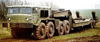
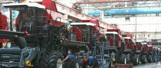
Progenitor
The new model of large-sized equipment was developed on the basis of the MAZ-500 truck, a modern and progressive truck at that time. It was a dump truck with an 11.2-liter diesel engine producing 180 horsepower. For the transport of goods, the standard model was equipped with wooden sides.
The maximum carrying capacity was 7.5 thousand kg. Modifications of the MAZ-500 model differed in different types of sides:
- The MAZ-500V had a metal platform in its design, which had a positive effect on transportation capabilities;
- The MAZ-500G had an elongated body, which made it possible to transport long materials.
Subsequently, these two main modifications were replaced by new representatives of heavy equipment - MAZ-503 (dump truck), MAZ-504 (tractor tractor) and MAZ-509, designed for transporting wood materials. Let's consider the first option in more detail.
MAZ 503: price, technical specifications, photos, reviews, MAZ 503 dealers
Technical characteristics of MAZ 503
| Year of issue | 1965 |
| Body type | Dump truck |
| Length, mm | 5785 |
| Width, mm | 2500 |
| Height, mm | 2650 |
| Number of doors | 2 |
| Number of seats | 3 |
| Trunk volume, l | — |
| Country of assembly | USSR |
Modifications of MAZ 503
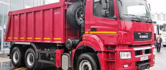
History of creation
The Minsk Automobile Plant progressively churned out model after model and their modifications. MAZ-503 was born as an upgrade from the MAZ-500 version. Production took place between 1966 and the mid-70s. In the anniversary year for the Minsk plant, 1970, the model was upgraded. The main difference from the “500” model was the reduced wheelbase and narrow focus - a mining dump truck. The stamped sections of the frame were fastened with rivets. It is located on four springs, respectively, located longitudinally. In addition, hydraulic shock absorbers operating telescopically are introduced into the suspension. The properties of the cabin changed in small details; it was also made entirely of metal and assembled by welding; in addition to three seats, there is one sleeping place.
The platform tilting mechanism is equipped with a hydraulic system operating in reciprocating mode. It was convenient that tipping and other body control operations could be carried out from the driver’s cab. A special valve was integrated into the system, which, after completion of loading, activated shaking of the loading platform for better discharge. For convenience, the steering system is equipped with power steering. Changes also affected the transmission; the main gear now had a higher gear ratio for the rear axle (9.57). The brake system applied only to the car and did not have the ability to connect a trailer (the brake valve was of the ZIL type).
It is interesting that in the MAZ-503V there was pneumatic control above the hydraulic system. The process occurs under the control of a pneumatic distribution valve. The cabin was provided with the same elements as in the “500th” MAZ. Manual windows, electric windshield wipers, floor mats, boxes for tools and personal items. For convenience, folding sun visors were even provided. Rear view mirrors are most likely not worth mentioning.