- home
- Media center
- Articles
- KAMAZ 43118 diagram
Menu
- News
- Articles
- Video materials
- Photo materials
- Publication in the media
- 3D tour
27.09.2019
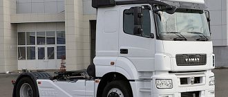
KamAZ-43118 is a fairly recent vehicle. It was produced from 2011 to 2016. At this time, this truck became one of the best-selling models of the Kama Automobile Plant. And in 2022, in general, it became the best-selling truck in Russia.
KamAZ-43118 van version
KamAZ 43118 - technical characteristics
KamAZ-43118 is an all-wheel drive truck with a 6 × 6 wheel arrangement. This vehicle, with its high cross-country ability, has become simply irreplaceable in hard-to-reach areas of Russia. Also, having a lifting capacity of 10 tons, the machine became the basis for a large number of various special equipment and, above all, truck cranes.
KamAZ-43118 has the following overall dimensions (in millimeters):
- Length – 8580;
- Width – 2500;
- Height – 3455;
- Ground clearance – 385;
- Wheelbase – 3960+1320.
The vehicle is equipped with a KamAZ-740.30-260 diesel engine that meets Euro-2 environmental standards. This power unit is made according to the V8 formula. It has a displacement of 10.85 liters, is equipped with a turbocharger and develops a power of 260 hp. With.
This power unit allows the car to reach a maximum speed of 90 km/h.
The empty weight of the truck is 10,400 kg. The weight of a fully loaded vehicle can be 20,700 kg.
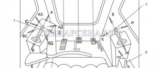
Controls in the cab of a truck crane based on KAMAZ
Cabin of truck crane KS-45721 Chelyabinets 25 tons
Truck crane Ivanovets
Cabin of truck crane KS 45721 Chelyabinets 25 tons
Russian miracle crane "OVOID"
Review of the Chelyabinets KS-55733-33 truck crane KamAZ 63501 | Ural Special Equipment Plant
Crane manipulator KANGLIM KS2056H Control
Automated training system “Crane operator”
IVANOVETS truck crane with ovoid boom
Kamaz 5511 mixer unloading concrete
Truck crane Chelyabinets KS 45721, 25 tons, Kamaz 43118 id3279
Also see:
- Put sloth on KAMAZ
- How to remove a hub on a KAMAZ
- KAMAZ from state storage 55111 and 65115 or conservation
- Spoiler for KAMAZ with maxi roof
- Assembling and disassembling the KAMAZ starter
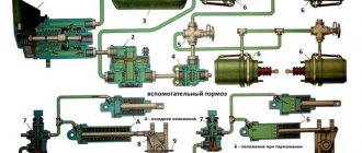
- Diagram of air movement in the KAMAZ brake system
- Hydrogen at KAMAZ
- Wheel hub bearing KAMAZ 4310
- KAMAZ injection pump tubes diagram
- KAMAZ engine degassing
- Auto KAMAZ next
- Color wiring diagram KAMAZ 43114
- Steel grade for KAMAZ springs
- Starter retractor KAMAZ
- KAMAZ problem with charging
Home » News » Controls in the cab of a truck crane based on KAMAZ kamaz-parts.ru
Composition of KamAZ electrical equipment
The KamAZ-43118 electrical equipment includes the following systems:
- Electricity supply;
- Light signaling;
- Lighting;
- Instrumentation;
- Heating systems;
- Windshield wipers;
- Sound alarm;
- Launcher.
Each of these systems has its own diagram, which will be given below. And we'll start with the power supply system.
Control of KAMAZ all-terrain vehicle | KAMAZ
Overview of the interior and controls of KAMAZ 65221)))
Kamaz off-road all-terrain vehicle
KAMAZ in the mud and ZIL in the swamp! All-terrain vehicles at work! Selection. Compilation of extreme off road
Off-road truck tractor KAMAZ (Batyr) and flatbed semi-trailer PPB 20-21-12K UST-94651 id5317
KAMAZ 4310, new
Gearbox on a Kamaz car (switching diagram) for subscribers
Kamaz all-terrain vehicle 44108, light gray
ZF Double H gearshift pattern
KAMAZ 43101 CONTROL-INSTRUMENTS
MTLB ALL-TERROAD VEHICLE PULLING OUT A STUCK KAMAZ IN THE SNOW OFF-ROAD NORTH MTLB, KAMAZ OFFROAD
Also see:
- Truck tractor KAMAZ 6460 load capacity
- Fastening the barrel to KAMAZ
- TTX KAMAZ 6520
- KAMAZ wheel composition
- Use of heating oil in KAMAZ
- KAMAZ master chassis
- How to find KAMAZ in GTA Criminal Russia
- KAMAZ van height
- How many tons of sand are in a KAMAZ dump truck?
- First gear ratio KAMAZ
- How to install one turbine on KAMAZ
- KAMAZ hit a car video
- KAMAZ divider cable with valve
- Watch a video about KAMAZ accidents
- Do-it-yourself KAMAZ cabin trim video
Home » New items » KAMAZ control all-terrain vehicle
kamaz136.ru
Power supply system for KamAZ-43118 vehicle
This system, perhaps, can be considered the main one in the car; thanks to this system, the truck is supplied with electricity when the power unit is running. The general diagram of the power supply system is presented below:
In the figure the numbers indicate:
- generator excitation winding cut-off relay;
- generator;
- fuse box;
- starter relay;
- starter;
- rechargeable batteries;
- mains switch;
- button for remote battery disconnect switch;
- heater motor relay;
- ammeter;
- fuses 13.3722 (7.5 A);
- fuse PR310 (10 A);
- instrument and starter switch;
I. to the EFU thermal relay
Brief explanations of the diagram:
The energy sources for this system are a generator (2) and two batteries connected in series (6). The negative terminal of the batteries, as in all cars, is connected to the housing. But, unlike passenger cars, on KamAZ it is connected through a special ground switch (7), which has a remote control.
Number 1 in the diagram shows a relay for disconnecting the generator excitation winding. This relay must break the circuit when the electric torch device (EFD), which is responsible for starting the engine in the cold season, is operating.
When the engine is running and the ignition is on (the ignition unit is indicated in the diagram as number 13), the circuit leading to the remote battery mass switch button (8) is opened. This is done so that the engine does not spontaneously turn off accidentally or as a result of a malfunction.
Let's look at the light signaling circuit next:
KAMAZ controls and pedals video
Cabin KAMAZ 4310, KHAKI color
installation of a floating system on KamAZ 53212
Auto-mentor. Basic car controls
KAMAZ dashboard
How to Move Off Smoothly (For Beginners).
Training video for VOLVO Fh22, Fh23 truck driver
K-701 how to drive a tractor | Kirovets | Review, Test Drive |
Cabin of KAMAZ concrete mixer truck, gray
Everyday life of Kamazist: Elimination of air leaks, repairs
The first Russian unmanned bus from Volgabus
Also see:
- Adjusting the clutch of the 154 KAMAZ gearbox
- Which antenna to put on KAMAZ
- Remote disconnect switch 24v KAMAZ
- Expansion tank KAMAZ 4310
- Luzar KAMAZ stove motor
- Bearing 306 KAMAZ
- KAMAZ 2022 strategy
- Replacing the KAMAZ euro heat exchanger
- KAMAZ 65115 engine Yamz 238
- KAMAZ brake drum approval
- KAMAZ test explosion
- How to remove the steering wheel play on a KAMAZ video
- Osago on KAMAZ 55111
- KAMAZ fuel tanker capacity
- Wheel stud KAMAZ 6522
Home » New products » KAMAZ controls and pedals video
kamaz136.ru
Warning light circuit diagram
This system controls the rear brakes and turn signals. It serves to notify other road users about the maneuvers the truck is making. The general diagram of this system is shown in the figure below:
The numbers on the diagram indicate:
- left lamp;
- right lamp;
- turn signal and hazard warning relay;
- fuse PR 119 (6 A);
- light switch;
- fuse 13.3722 (7.5 A);
- fuse PR 310 (10 A);
- hazard warning light switch;
- turn signal right
- left turn indicator;
- rear left lamp
- rear right lamp;
- brake light switch;
- trailer solenoid valve switch;
- brake signal relay;
- sound signal (buzzer);
- 18, 19 — switches for pressure drop alarms in the brake air drive receivers;
- parking brake warning switch;
- relay-interrupter for the parking brake system activation indicator;
- reverse light switch;
- reversing light;
- trailer socket 24 V;
- center differential lock warning switch;
- 27, 28 — signaling units;
- oil filter clogged warning switch;
I. to the instrument and starter switch;
II. to the coolant temperature gauge;
III. to the tachometer;
IV. to the speedometer.
This scheme includes the following subsystems:
- Hazard warning system;
- Brake (stop) indicators;
- Direction indicators
- Indicator lamps for turning on the direction indicators of the vehicle and trailer;
- Center differential lock indicator lamps,
- Parking brake system;
- Drops in air pressure in the pneumatic drive circuits of brake mechanisms;
- Warning lamp blocks,
In addition, the system includes a variety of switches and relays.
Brief explanations of the diagram. Under the number 8 hides the well-known “emergency warning light”. That is, this switch turns on all the direction indicators at once.
The turn signals themselves, in normal mode, are turned on by a combination light switch, marked in the diagram with the number 5. Their intermittent lighting is provided by a special relay (3).
The driver observes the operation of the direction indicators thanks to the signal lamps (26), while the vehicle and the trailer have different signal lamps.
The braking signal to the feet comes from a pneumoelectric sensor (13). The signal from it goes through the intermediate relay (15), and then to the stop lamps. I draw your attention to the fact that the stop circuit is connected via an ammeter, and is not connected by the instrument switch and starter. This is done so that the stop lights light up even when the ignition is turned off.
You need to know that the brake alarm turns on even when the parking brake is applied - the handbrake. The sensor marked on the diagram with the number 20 is responsible for turning on the stops when the handbrake is turned on. When the parking brake is applied, the stops light up intermittently. This operation is ensured by a relay-interrupter (21).
Warning lamps
| Emergency oil pressure in the engine lubrication system (color – red) | ||
| Turning on the high beam headlights (color – blue) | ||
| Activation of the parking brake system (color – red, intermittent) | ||
| Emergency (color – red) | ||
| Low battery (color – red) | ||
| Trailer/semi-trailer direction indicator (color – green, intermittent) | ||
| Vehicle turn signal to the right (color – green, intermittent) | Depending on the vehicle's equipment, the left/right turn indicator lamps may light up simultaneously | |
| Vehicle left turn indicator (color – green, intermittent) | Depending on the vehicle's equipment, the left/right turn indicator lamps may light up simultaneously | |
| Turning on the center differential lock (color – orange). Not available for 4x4 vehicles | ||
| Turning on the cross-axle differential lock on the 2nd axle (color – orange) | ||
| Turning on the cross-axle differential lock for the 3rd axle (color – orange) | ||
| PTO activation (color – green) | ||
| PTO activation (color – green) | ||
| Turning on the traction control system (color - orange) | ||
| Tractor ABS malfunction (color – orange) | ||
| Trailer/semi-trailer ABS malfunction (color – orange) | ||
| Turning on the transfer case center differential lock (color – orange) | ||
| Malfunction in the engine management system (color - orange) | ||
| Malfunction in the exhaust gas aftertreatment system and/or engine (color - orange) | ||
| ECU readiness (for KAMAZ engine) or control lamp of electric intake air heater (for Cummins engine) (color - orange) | ||
| Air filter clogged (color – red) | ||
| The cabin is not locked with a hydraulic lock (color – red) | ||
| Turning on cruise control (color - green) | ||
| Brake system malfunction (color – red) | ||
| Turning on the low range in the range multiplier (color - orange) | ||
| Turning on fuel heating in the FGOT and fuel intake (color - orange) | ||
| Turning on the transfer case downshift (color – red) | ||
| Turning off the fan clutch drive (color - orange) | ||
| Turning on the retarder/intarder (color – orange) | ||
| Low liquid level in the neutralization system (color – blue) | ||
| Presence of water in the fuel coarse filter (color – red) | ||
| Low coolant level (color - orange) (for certain trim levels) | ||
External and internal lighting system KamAZ-43118
In addition to external lighting, this system is also responsible for lighting inside the vehicle’s cabin. It includes the following devices:
- headlights;
- fog lights;
- front lights;
- rear lights;
- engine compartment lamp;
- lamp for lighting the glove compartment and bed;
- instrument lighting lamp;
- cabin lighting lamp;
- portable lamp.
It has the following scheme:
- right fog lamp
- left fog lamp;
- right headlight
- glove box lamp;
- lamp switch;
- road train lights;
- road train light switch;
- heater motor relay;
- left cockpit light;
- right cockpit light;
- left headlight;
- fog light switch;
- brake signal relay;
- trailer solenoid valve switch;
- rear right lamp
- rear left lamp;
- front right lamp
- front left lamp;
- combination light switch;
- fuse 13.3722 (7.5 A);
- fuse PR 310 (10 A);
- instrument lighting switch;
- engine compartment lamp;
- hazard warning light switch;
- portable lamp socket;
- seven-pin socket;
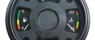
- oil pressure indicator;
- fuel level indicator;
- speedometer;
- tachometer;
- coolant temperature gauge;
- ammeter;
- pressure gauge;
I. to the instrument and starter switch
All devices, except for the glove compartment light, are connected using a single-wire circuit. As for the glove box lighting lamp, its negative contact is connected to the fuse block.
As for the low and high beams (numbers 3,11), dimensions, fog lights (1,2), they are turned on and off by a combination switch (19) connected through an ammeter.
To protect low beam headlights, as well as fog lights, from short circuits, they are powered through PR310 thermobimetallic fuses. High beams have their own fuses.
The size circuits and instrument lighting lamps are also protected from short circuits by thermobimetallic fuses of type 13.3722.
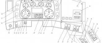
Instrumentation system
As you might guess from the name, this system is designed to service various instrumentation, indicators and sensors. Instruments are located on the dashboard of the car, and sensors are located in its various components and mechanisms.
The electrical diagram of this system is as follows:
The numbers on the diagram indicate:
- fuel level indicator;
- fuel level sensor;
- fuse 13.3722 (7.5 A);
- coolant temperature indicator sensor;
- coolant overheat sensor;
- emergency oil pressure sensor;
- oil pressure indicator sensor;
- oil pressure indicator;
- 11 — blocks of warning lamps;
- coolant temperature gauge;
- generator;
- tachometer;
- speedometer;
- speedometer sensor;
I. to the instrument and starter switch
KAMAZ 43118 description of the instrument panel
Overview of the interior and controls of KAMAZ 65221)))
Cabin structure of KamAZ 43114
KAMAZ Euro-3 instrument panel assembled.
KAMAZ dashboard
Kamaz colt start euro 4
KAMAZ 65115
Automotive simulator "KAMAZ-Master-01" (original dashboard of a KamAZ car)
KamaZ generator operation.
Speedometer KAMAZ Euro 3
CAN Rewinding the Kamaz euro4 speedometer into the OBDII connector www.odovrn.ru
Also see:
- Instructions for new KAMAZ trucks
- KAMAZ will crush you
- KAMAZ seat upholstery
- KAMAZ electric traction
- KAMAZ clutch adjustment technology
- Seat KAMAZ euro mechanical
- Interaxle differential KAMAZ 65116
- KAMAZ 4310 axle gearbox housing
- Center distance on KAMAZ
- Belaz against the background of KAMAZ
- What is the fuel consumption of KAMAZ at idle speed?
- KAMAZ starter mounting bolts
- KAMAZ 65116 019
- Cooling system of KAMAZ 55111
- KAMAZ 43118 fuel consumption per hour
Home » Video » KAMAZ 43118 description of the instrument panel
kamaz136.ru
Electrical diagram of the heating system, sound alarm and windshield wiper systems
This system is responsible for the operation of the heating system of the car, or in common parlance, the stove. In addition, it is responsible for powering the wipers and sound signal. This system has the following electrical diagram:
- heater electric motor;
- heater motor switch;
- wiper;
- heater motor relay;
- fuse 13.3722 (7.5 A);
- fuse PR 310 (10 A);
- windshield washer switch;
- windshield washer,
- wiper switch;
- combination light switch;
- sound signal (buzzer);
- tonal signals;
- horn relay;
I. to terminal AM of the instrument switch and starter;
II. to the short circuit terminal of the instrument switch and starter;
III. to the brake signal relay;
IV. to the signaling unit.