06.05.2021
To control the movement of the MKSM-800 or MKSM-1000 loaders, their main and replaceable equipment, levers and switches are used, located inside the driver’s cabin. It is designed taking into account the requirements of ergonomics and the ability to control all functions of the MKSM.
Figure 1 — Controls 1 — motion control lever; 2 — control pedal for replaceable attachments; 3 — friction clutch pedal; 4 — fuel pedal; 5 — operating equipment control lever; 6 — manual fuel supply handle; 7 - protective lever.
Features of electrical equipment
In the MKSM-800 and MKSM-1000 loaders, two batteries with a generator act as sources of electrical energy. It is mounted on the engine and works in parallel with the batteries. The rated voltage for the generator is 14 V. When the engine is not running, as well as at low generator speeds, the electrical devices of the loader consume electricity from the batteries (in this case, the indicator light (12) Fig. 2 will light up).
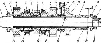
Figure 2 - Right panel 1 - switch for turning on headlights;
2 — battery switch; 3 — switch for turning on the cabin glass washer; 4 — operating time counter; 5 — sound signal button; 6 — control lamp for turning on the direction indicators; 7 — direction indicator switch; 8 — temperature sensor; 9 — operating equipment control lever; 10 — switch for turning on the starter and instruments; 11 - light indicator of engine operation; 12 — light indicator of battery discharge; 13 — light indicator of emergency oil pressure in the engine; 14 — light indicator of emergency temperature of the engine cylinder head; 15 — light indicator of air filter contamination; 16 — light indicator for engine preheating. The nominal voltage in the MKSM-800 electrical equipment system is 12 V. Depending on the functional purpose, the electrical devices of the loader are connected either to the battery or to the generator. Connect directly to the battery:
All other electrical devices are connected to the generator.
Engine characteristics
MKSM loaders are equipped with various diesel engines imported from the USA, Japan and Germany. They vary in power, have a different cooling system and a different number of cylinders. All these differences determine the modification of the loader.
| Options | Modifications of MKSM | ||||
| 800 | 800K | 800N | 800A | 800A-1 | |
| engine's type | diesel | diesel | diesel | diesel | diesel |
| Engine make | Cummins A2100 | Cummins A2300 | Hatz 3M41 | Cummins A2300 | Kubota V2403 |
| Number of cylinders | 3 | 4 | 3 | 4 | 4 |
| Cooling option | liquid | liquid | air | liquid | liquid |
| Engine power, kW/hp | 34/46,2 | 32,4/44 | 38,9/52,9 | 35,3/48 | 37,5/51 |
Return to navigation
Connecting electrical system devices
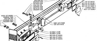
The switching circuits of electrical devices are protected by fuses of the appropriate rating; they are located on the left panel. The layout and connection diagram of electrical equipment is shown in Figure 3.
Figure 3 - Electrical diagram of the machine 1, 72 - (EL5, EL6) - flashlight 23.3712 with lamp A12-5 and A12-21-3; 2, 71 - (EL2, EL3) - headlight FG-152 AB"O" with lamp AKG-12-55; 3 - (PP) - right panel; 4, 70 - (EL13, EL1) - front working headlight FG-152 AB"O" with lamp AKG-12-55; 5, 22, 23, 49 (X8, X2, X3, X5) - connector 02-6.3-04; 6 (A1) — control and display unit (supplied with the HATZ engine); 7, 54, 56, 58, 63, 64 (HL1, HL4, HL5, HL6, HL3, HL2) - indicator light 121.3803010 with lamp A12-1; 8, 26, 34 (X7, X9, X10) - connector 02-6.3-06; 9 (K2) - relay 73.3747; 10 (SA2) - switch 5102.3709; 11, 65, 66 (SA3, SA9, SA8) - switch P147; 12 (SA4) - switch P150; 13, 55, 57, 59 (K6, K5, K4, K3) - relay 735.3747 or 90.3747; 14 (SA6) — switch VK 322; 15 - (RT) - operating time counter SVN-2-01; 16 (SA7) — battery switch (VN-45M); 17, 18 (EL12, EL14) — license plate light 12.3717; 19, 20 (EL9, EL10) - lampshade 21.3714 with lamp AC12-5-1; 21 (EL11) — flashing light FPM-2M with lamp KGM-12-50-1; 24, 25 (SA11, (SA12) - switch 4602.3710; 27, 48 (EL7, EL8) - rear lamp 33.3716 with lamps AC12-5 and A12-21-3 or rear lamp 71.3716 with lamps A12-21-3 and A12- 21+5-2; 28 (M4) - electric motor of the fan-dust separator ME236; 29 - (EK) - heater (supplied with the engine; m HATZ); 30 - (S4) - oil pressure sensor in the system (supplied with the HATZ engine) ; 31 - (S5) - engine emergency temperature sensor (supplied with the HATZ engine); 32 - (Y) - fuel pump solenoid valve (supplied with the HATZ engine); 33 - (S6) - air filter contamination sensor (supplied with the HATZ engine ); 35 - (M1) - starter (supplied with the HATZ engine); 36 - (G3) - generator (supplied with the HATZ engine); 37 - (A2) - power automation unit (supplied with the HATZ engine); 38, 40 - (G2, G1) - rechargeable batteries; 39 (K1) - switch 1300.3737 41 (S1) - drain oil filter clogging sensor 533-9-62-19-1145-1K; 42 (S2) - pressure oil filter clogging sensor 533- 9-62-19-1247-1K; 43 (S3) — hydraulic system oil level sensor 533-9-62-19-1141-1K; 44 (B2) — temperature indicator sensor TM100-A; 45 (B3) - fuel level indicator sensor 23.3827; 46, 69 (NA2, NA1) - sound signaling device 201.3721-01; 47 (EL4) - headlight 30.3711 with lamp A12-50; 50 (X1) — socket of portable lamp PS500; 51, 52 (X6, X4) - connector 02-6,3-08; 53 (FU) - fuse block Pr 121; 60 (T) — temperature indicator receiver UK 145-A; 61 (HL7) - control lamp A12-1; 62 (P2) — fuel level indicator receiver 13.3806; 67 (P1) — turn signal switch RS950K; 68 (PL) - left panel; 73 (M2) — windshield wiper motor ME237-B; 74 (M3) — windshield washer motor ME268; 75 (B1) — heater temperature sensor AIRTRONIC D2; 76 (A5) — mini heater regulator AIRTRONIC D2; 77 (FU11) - 5 A fuse for AIRTRONIC D2 heater; 78 (FU12) - 20 A fuse for AIRTRONIC D2 heater; 79 (A3) - AIRTRONIC D2 heater control unit; 80 (A4) - metering pump of the AIRTRONIC D2 heater.
WARNING: Commissioning of a dry-charged battery located on the right wing requires its removal from the skid steer, filling with electrolyte and charging according to the procedure.
After these procedures, the battery is installed in its normal place and connected according to the battery connection diagram (Figure 4).
Figure 4 — Battery connection diagram 1 — right battery;
2 - switch 1300.3737; 3 - left battery. Before starting work with MKSM-800, you need to turn on the battery for 2 seconds (no more). To do this, press the switch (2) (Fig. 2). When work is completed, the battery is turned off.
WARNING: The battery must be disconnected no earlier than 4-5 minutes after turning off the heater. This is necessary for normal purging of the heater boiler from combustion products and to prevent it from becoming coked. Failure to comply with this rule may result in heater failure.
Source
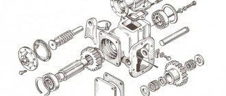
Design
Structurally, the drive has:
- handle (1) (Figure 2), which is attached to the console (3) of the left wall of the cabin;
- rope (5) with fastening elements;
- valve block (14);
- high pressure hoses (15, 16, 20, 21);
- pipelines with connecting fittings (12, 17, 19, 28, 31, 34, 35, 36).
Figure 2 — Drive for controlling the parking brake and locks 1 – lever;
2 – axle; 3 – console; 4,11,25,27,40 – nut; 5 – rope; 6 – bar; 7,18,30,33,37 – bolt; 8 – clutch; 9 – fuse; 10 – washer; 12,17,19,28,31,34,35,36 – pipeline; 13,29,38 – fitting; 14 – valve block; 15,16,20,21 – sleeve; 22 – clamp; 23 – futorka; 24 – shoulder; 26 – thrust; 32 – gasket; 39 – clip; 41 – sheet; 42 – screw. A second console is attached to the right wall of the MKSM-800 cabin; the second end of the lever (1) is locked in it (it is in the “Lever down” position).
To hold the lever vertically, a clip (39) is used, secured to the sheet (41) with bolts and nuts (40). The lever (1) is connected by means of a rope and quick-release clutches (8) to a rod (26), which is connected through the shoulder (24) to the spools of the valve block (14). The block includes two identical valves, each of which has:
- body (1) (Figure 3);
- spool (2);
- liner (3);
- washers (8 and 11);
- spring (9);
- shoulder (14).
Figure 3 - Parking brake valve 1-body;
2 - spool; 3 - liner; 4.5 - ring; 6 — retaining ring; 7 — oil seal; 8.11 - washer; 9 - spring; 10,12,13 - nut; 14 - shoulder; 15 - bolt; 16.18 - gasket; 17.19 - fitting. To fix the spool (2) and the liner (3) inside the housing, a locking ring (6) is used. The position of the arm (14) in relation to the body (1) is adjusted using a bolt (15) and nuts (12). Hoses and pipelines are connected using fittings (17), (19). To ensure normal sealing, rubber rings (4), (5), as well as gaskets (16), (18) are used.
MKSM 800 Service Manual
The manual contains technical data of the MKSM loader, a description of its design, instructions for servicing and caring for the machine, as well as lubrication, safety rules when working with the loader and transporting it. By correctly following the instructions given in this manual, malfunctions and injuries can be avoided, and therefore it is necessary that personnel dealing with the MKSM 800 mini loader be sufficiently familiar with the contents of this manual before starting any work.
In view of the constant improvement of products and their parameters, the manufacturer reserves the right to make appropriate changes to the design of the MKSM 800 mini loader.
The universal mini loader MKSM is designed for loading, leveling and moving rocks of classes 1-4 using the main bucket, digging narrow trenches, drilling holes in rocks of classes 1-2 using appropriate interchangeable working equipment.
Types of attachments
The main loading bucket, which is equipped with all types of MKSM loader, can be easily replaced with any other attachments in the arsenal of this mini-machine, namely:
Quarry bucket . For working with non-flowing and coarse-grained materials (crushed stone, stones, construction waste, etc.), and has a bucket volume of almost 0.5 cubic meters and a width of 173 cm. Equipped with special teeth on the edge.
Bulldozer rotary blade . It is used for cleaning winter roads from snow, platforms from debris, for soil leveling, filling and leveling holes. Its width is 220 cm.
Main working body
Bucket excavator . It is used for excavating small soil layers: trenches, holes, ditches, etc. Its capacity is 0.08 cubic meters, it rises to a height of 2 meters and goes deep to a depth of 2.4 m.
Trench excavator . It has a narrower specialization than the previous one, and is used for digging trenches necessary for laying cables, pipes and other communication units. Digs a trench with a maximum depth of 1 m, its width is 0.16 m, and works at a speed of 3.8 m/h.
Load forks . They are used during the storage of any stackable goods, for example, wooden pallets with construction or other goods during work in a warehouse, construction site or terminals. The working width varies from 23 cm to more than one and a half meters, and lifts to a height of 3.06 m.
Pressing forks . Used for collecting, loading and local movement of bulky and long waste, for example, construction waste (boards, beams, etc.), tree branches, bales or stacks of hay and straw, etc. They capture 162 cm and lift to a height of 3.01 m.
Weight pin . Used for moving or loading rolled materials: paper, wire, textiles, etc. The pin is 98 cm long and rises to a height of 3 m.
Load boom . With the same technical data as the pin, used for loading and unloading, lifting or transporting particularly heavy loads (up to 800 kg), a lifting hook is used to complete the task.
Drilling equipment . It is used for drilling wells in the ground, with different diameters and depths (20-40 cm in diameter and up to 2 m in depth), which can be used for a wide variety of work: from landscaping areas to constructing foundations and supports.
Hydraulic hammer . Used for crushing. With an impact force of 480 J, it breaks rocks and stones, concrete slabs and old asphalt, etc.
Road brush . Street cleaning. The tank contains 200 liters of water, and the brush covers 155 cm of surface.
Cleaning machine . Performs similar functions as a brush, but without the use of water and with the ability to reach hard-to-reach places, for example, a line near the curb, fences, etc. Coverage of the area during cleaning - 2 m.
Spreader with hopper . Used for sprinkling slippery roads. The volume of the bunker is 0.4 cubic meters, scatters at a distance of 3-16 m.
Milling rotary snow blower . Clears and discards snow cover from the treated surface. Captures 172 cm and throws 5 m.
Concrete mixer . It is used for mixing concrete mixtures directly on the construction site. Volume – 250 l.
Technical description of the units
The drive of the MKSM 800 mini loader is provided by a transmission with a Zetor 5201 diesel engine, which is rigidly connected to the pump drive and to the NPA 33 travel pumps and the U32l working equipment pump. The final drives are driven from the MPA 33 hydraulic motors and provide constant drive to the front and rear wheels of the mini loader . The hydraulic oil cooler and the mini loader cooling system radiator are located in front of the engine. The fuel tank is located on the right side, the hydraulic tank is located on the left side in the inner frame. The RSK16T3 distributor is located in front of the adjustable pumps NPA 33 under the hydraulic filter of the working fluid. To provide convenient access to individual units of the MKSM 800 loader, the safety-type cabin tilts after first disconnecting the hinges in the loader cabin. The cabin contains all the controls and controls, instrumentation and the operator’s seat. All this together forms a single assembly unit. The loader wheels are attached to final drives, mounted on different sides of the loader frame. The heating is located on the left side of the cabin from the inside. The batteries are located on the right and left wings. Access to them is possible after lifting the covers, which are equipped with a motorcycle lock.
The MKSM 800 mini loader is equipped with a Zetor 5201 diesel engine, which is installed elastically. Access to the engine opens from the rear after lifting the rear radiator shroud and from above after tilting the hood and cab. This is a four-stroke, three-cylinder, water-cooled diesel engine with direct fuel injection. The crankshaft housing is cast from gray cast iron, one-piece, with a flange for mounting the pump drive. The cylinder head for each cylinder is independent, the cylinder liners are replaceable.
The engine cooling system is liquid with forced circulation and with a thermostat. The lubrication system is pressure circulation with a wet bath; the MKSM loader is equipped with a two-stage or replaceable oil filter. The fuel supply system consists of a fuel pump, a mechanical all-mode regulator and a fuel priming pump. The Zetor 5201 engine is cooled by forced circulation liquid, which is provided by a centrifugal pump mounted on the front of the engine crankcase and driven through a water pump via a V-belt drive. The cooling system includes a small circuit with a thermostat that ensures rapid heating of the engine to an operating temperature of up to 80 degrees. There is a filler cap on top of the radiator, and the coolant drain valve is located on the bottom left side of the radiator. The power system of the MKSM loader consists of a fuel tank, a fuel supply system on the engine and fuel pipes. The fuel tank is located on the right side of the rear with a filler pipe behind the cab. The fuel tank capacity is 55 liters. From the bottom of the tank, fuel is sucked in by the fuel priming pump through the fuel pipeline. A fuel coarse filter is installed on the lower part of the fuel priming pump. From the fuel lift pump, diesel fuel is forced into the Motorpal fuel pump through a single stage fuel filter. The fuel pump forces fuel through high-pressure pipes into the injectors. Excess fuel from the engine injectors goes through the drain pipe back into the fuel tank.
Hydraulic system of MKSM 800 loader
Serves to drive working equipment and running gear. It consists of two hydraulic circuits: the working equipment circuit and the chassis drive circuit.
Contour of working equipment MKSM 800
Travel drive circuit MKSM 800
It consists of two NPA 33 hydraulic pumps and two MPA 33 hydraulic motors. This circuit is protected by a pressure of 35 MPa using high pressure safety valves built into the MPA 33 hydraulic motors. The working fluid tank, radiator and filter are common to both circuits. The capacity of the hydraulic tank is 55 liters.
Pump drive MKSM 800
The pump drive consists of a power take-off and clutch, which together form one unit.
Control of the pump drive is reduced to disconnecting it from the engine, especially to facilitate engine starting at lower temperatures. This operation is performed mechanically by the clutch pedal located in the operator's cabin.
The pump drive housing is equipped with flanges for mounting two adjustable pumps NPA 33, which provide drive for the running mechanism, and one gear pump U 32l, which charges the hydraulic system of the working equipment. From adjustable hydraulic pumps, torque is transmitted hydrostatically to MPA 33 hydraulic motors through high-pressure hoses. From the hydraulic motor, torque is transmitted to the final drives using gears that are located between the hydraulic motors and the final drives. The design of the gear assembly allows the loader to be braked using the force of disc springs. The loader is braked using a safety lever which is mechanically connected to the parking brake bypass valve when the safety ramp is folded down. The bypass valve releases pressurized oil into the drain branch of the hydraulic system (which ensures the release of the loader), as a result of which the loader is braked. The raised safety lever provides protection against spontaneous or uncontrolled movement of the MKSM 800 loader.
MKSM 800 loader control
Attention ! When learning to operate the MKSM 800 loader, levers and handles must be moved carefully. The clutch can only be used when starting the engine in cold weather, and the clutch can be depressed for a maximum of 1 minute. It is strictly forbidden to use the clutch while the engine is running. In this case, it threatens to destroy the clutch and bearing.
Starting the engine at low temperatures.
When operating the MKSM 800 loader in winter conditions, changing the oil and oil filter at intervals recommended by the manufacturer plays a very important role, since the viscosity of the oil may increase during operation. Thus, when the engine is started, the condensed oil flows around the engine oil filter, which ultimately means that oil enters the engine without being filtered. As a result, engine wear increases several times.
It is recommended to integrate an electric antifreeze heater into the motor block using an external 220V energy source, which preheats the coolant to a temperature that meets the summer operating conditions of the MKSM loader. Before starting, it is recommended to turn on the low beam briefly. It is imperative to depress the clutch to disengage the hydraulic pumps and drive the pumps.
We work for you from Monday to Friday from 9 am to 18:00.
Source
Technical characteristics of MKSM-800
MKSM-800 is a municipal construction multi-purpose machine for performing various works:
The listed works are carried out through the installation of attachments and good performance characteristics of special equipment. The MKSM-800 model can develop a load capacity of up to 800 kg, and the MKSM-1000 model – up to 990 kg. The generated traction force is 24 kN, and the magnitude of the static tipping load is 16·10 3 N. This is enough to work with such attachments as:
The mini loader can operate on terrain with a maximum slope of 5°. Its parking brake holds the machine on a slope with a maximum angle of 13°.
Power transmission and hydraulic system
The MKSM-800 loader uses a volumetric hydraulic drive with a gear transmission. It provides an independent smooth change in the speed of rotation of the left/right final drive. Two adjustable axial plunger hydraulic pumps are installed, which supply working fluid to two axial plunger unregulated hydraulic motors. The pumps are driven by a gear reducer equipped with a single-disc friction clutch.
The basis of the hydraulic system of mini loaders is a gear pump, which provides a working pressure of 16 MPa. This pressure is sufficient to guarantee uninterrupted operation of both the components of the loader itself and the active attachments. The efficient distribution of working fluid flows is facilitated by a distributor of the MKRN type. Cleaning the liquid from possible contaminants is carried out using two oil filters: pressure and drain.
Hydraulic system operation diagram
When the safety lever (7) (Fig. 1) is raised, the valves (11) (Fig. 2), (16) move to the left as shown in the figure. In this case, the pressure outputs of the feed pumps (19) are disconnected from the hydraulic pump control mechanisms (10, 17), which are connected to the tank drain line (29). As a result, the axial piston pumps (20) switch to idle mode, which eliminates the possibility of the MKSM-800, MKSM-1000 mini loader moving when the control lever (1) is accidentally pressed (Figure 1).
Figure 2 - Diagram of the hydraulic system 1 - plug; 2- quick release coupling; 3 — block of secondary make-up and safety valves of the bucket “pull” (18 MPa); 4 — block of secondary make-up and safety valves of the bucket “pull away” (5 MPa); 5- bucket hydraulic cylinder; 6 — block of secondary make-up and safety valves for boom lift (18 MPa); 7 — boom valve; 8 — boom hydraulic cylinder; 9 — block of secondary make-up and safety valves for lowering the boom; 10.17 - hydraulic pump; 11 — brake and travel blocking valve; 12.14 - hydraulic motor; 13 — safety valve (36 MPa); 15 — low pressure line valve; 16 — valve for blocking travel and working equipment; 18 — control pressure valve; 19 — feed pump; 20 - axial piston pump; 21 - radiator; 22 - valve (170 kPa); 23 - valve (200 kPa); 24 - drain filter; 25.33 — contamination sensor; 26 - valve (20 kPa); 27 — temperature sensor; 28 - pump; 29 — hydraulic tank; 30 — level sensor; 31 - valve (0.65 MPa); 32 - pressure filter; 34 — blocking valve; 35 - primary safety overflow valve (16 MPa); 36 — distributor; 37, 39 — check valve; 38 — spool; 40.41 - block of secondary make-up safety valves (18 MPa).
Electrical equipment
The basis of the electrical system of the MKSM-800 mini-loader is two batteries, providing an operating voltage in the on-board network of 12 V. The following brands of batteries can be installed on the loaders: 6 ST-90A, 6 ST-90AP, 6 ST-75AP, their capacity is 75 or 90 Ah. The engine is started by a HATZ starter; the generator is supplied with the engine.
To illuminate the working path there are four FG-152 lanterns, two of which are located in front, and two in the back. Front and rear lights and a flashing light are used as light and road signaling.
Dimensions and weight
The weight of the MKSM-800 loader, as well as its overall dimensions, are almost the same for all modifications. And only the MKSM-800A model is an exception.
| Options | Modifications of MKSM | ||||
| 800 | 800K | 800H | 800A | 800A-1 | |
| Track width, cm | 141.0 | 145.0 | 141.0 | ||
| Ground clearance, cm | 20.6 | ||||
| Length, cm | 248.0 | 264.5 | 248.0 | ||
| Width, cm | 168.0 | 172.0 | 168.0 | ||
| Height, cm | 206.5 | 205.5 | 206.5 | ||
| Total weight, t | 2.8 | 3.1 | 2.8 | ||
Return to navigation
Chassis
MKSM-800 is a four-wheeled loader that uses tires measuring 10.0/75-15.3 to move it. They allow the equipment to successfully work on soils with low bearing capacity, the optimal operating pressure is 240 kPa. The equipment can be equipped with wheels with discs measuring 9...15.3, and it is also possible to install tracks for working on clay and swampy soils. The loader and its attachments are controlled using joysticks from the driver's seat.
Hydraulic oil cooling
Cooling of the MKSM-800 working fluid is ensured when it is discharged from the drain line through the valve (15) into the radiator (21). The speed and direction of movement of the loader are determined by moving the control lever (1) (Fig. 1).
To control the operation of the main equipment, a lever (5) is used (Fig. 1), and a pedal (2) is used for replaceable attachments. When exposed to them, the spools 38 (Fig. 2) of the distributor (36) move, and the overflow fuse (35) goes into operating mode (the pressure line is disconnected from the drain).
Fluid is supplied to the skid steer functional equipment by means of a pump (28), which directs it through the pressure section of the distributor (36), the check valve (37) and the corresponding spool (38). She can do:
- raising the boom – to the cavities of the hydraulic cylinders (8);
- displacement of the bucket “away from itself” – towards the cavities of the hydraulic cylinders (5);
- operation of replaceable attachments - to the quick-release couplings (2) (to the right - pedal travel (2) (Figure 1) forward and to the left - pedal travel back).
Protection of the loader elements from overload when the spools are in the operating position is carried out through the primary overflow fuse (35). When the spools are located in the neutral position, the working units are protected from overloads by means of secondary make-up fuses.
Loader MKSM-800
The MKSM-800 loader is a multi-purpose municipal construction machine, ideal for moving and loading soil (bulk materials), leveling terrain, drilling wells, digging trenches, clearing areas of debris and snow, and transport and storage operations with single loads.
Model MKSM-800 is a product of CHETRA. Thanks to its small dimensions and versatility, this loader efficiently and quickly performs large volumes of work in cramped conditions (alleys, city streets, markets, parking lots), where it is impractical to use conventional municipal equipment. MKSM-800 fits into openings 1.8 m wide and 2.1 m high, which again allows it to be used for maintaining pedestrian paths and sidewalks, landscaping and road maintenance. The model is distinguished by high speed and performance.
Performance characteristics
MKSM loaders, regardless of the model subtype, have a bucket in their arsenal and have the same load capacity, however, the method of controlling the hydraulic system, the speed of movement of the machine and the traction force of the loader vary depending on the modification.
| Options | Modifications of MKSM | ||||
| 800 | 800k | 800H | 800A | 800A-1 | |
| Max. travel speed, km/h | 10 | 18 | 12 | ||
| Max. weight of the lifted load, tons | 0.8 | ||||
| Max traction force, kN | 24 | 21 | 28 | 25 | 27 |
| Basic bucket capacity, m3 | 0.46 | ||||
| Width of base bucket, cm | 173.0 | ||||
| Max. bucket unloading height, m | 2.41 | ||||
| Max. boom radius, cm | 64.0 | ||||
| Drive unit | mechanical | electric | mechanical | ||
Tire set Return to navigation
Video in action
It is no coincidence that special equipment is called multifunctional. Thanks to a wide range of replaceable equipment, MKSM-800 is used to perform a variety of tasks. Moreover, you can equip the equipment with the necessary device in a matter of minutes, and the process itself does not require the involvement of an experienced specialist. The loader operates both indoors and outdoors. Tests carried out by CHETRA before the start of serial production of the model showed its high efficiency when performing harvesting, repair and earth-moving work using a variety of equipment.
MKSM-800 is an ideal option when it is necessary to carry out basic or auxiliary work, but there is not enough space for large-sized and powerful equipment. A small loader pays for itself quite quickly, often being more cost-effective than larger models.
MKSM-800 turns almost in one place and smoothly changes speed thanks to the presence of a volumetric hydraulic drive and the possibility of stepless speed switching. Operating the loader is extremely simple. All operations are carried out using a pair of joysticks located on the side panels.
This model, in comparison with analogues, has the following distinctive features:
Until recently, CHETRA offered customers two modifications of MKSM-800, differing in indexes. The MKSM-800K model was equipped with a Cummins (or John Deere) diesel unit, the MKSM-800N version was equipped with a Hatz engine. Now A-series loaders are again available on the market, having received design changes. New modifications have a welded frame, and the gear drive of the pump has disappeared. To optimize the launch of the power plant at sub-zero temperatures, a clutch is installed in the MKSM-800A models.
The latest modification of the loader was the MKSM-800A-1 version, which debuted at the YugBuild-2013 exhibition. This model received pneumatic wheels with tubeless tires and a modified suspension.
Device
MKSM-800 is equipped with hydraulic systems produced at enterprises located in Kovrov, Pargolovo or Salavat. Their only difference is the method of removal of wear products.
CHETRA's loader is valued for its versatility. The model works with 17 types of attachments: a road brush, a snow blower, a unit for spreading anti-ice materials, a rotary blade and other devices. The equipment can be changed in a matter of minutes using a quick-release clamp. No specialized tools are required.
The all-metal operator's cabin of the MKSM-800 deserves special attention. It is hinged to the frame using silent block connections. It can be folded back and fixed for servicing the units and components of the loader. The door forms the front wall of the operator's cabin, with clothes hangers installed on the sides. Inside the operator's cab there is a sprung seat that can move longitudinally. Next to it is the washer reservoir. The operator's cabin contains all controls and devices, as well as indicators and instrumentation. There is also a box for accessories and tools. The front window of the operator's cab provides excellent visibility and is cleaned by a windshield wiper driven blade. The glass at the back serves as an emergency exit, and on the side there are windows with windows. Modern thermal insulation and a powerful heater maintain the required temperature in the forklift operator's cabin. Additionally, a dust separator fan is installed, which reduces the level of dust in the operator's cabin. By replacing windows and doors with protective grilles, the MKSM-800 operator's cabin can be transformed into a lightweight version. The safety belt and bar, safety bars and door locking feature ensure operator safety.
Another advantage of the CHETRA loader is the availability of spare parts for it. You can buy them not only in specialized centers, but also in ordinary stores and markets.
How much does the MKSM-800 loader cost?
The price of the MKSM-800 loader is in the range of 1-1.1 million rubles, which is an adequate price for multifunctional and reliable equipment.