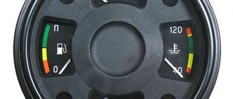
Dashboard ZIL-131
Cabin
Aleks095 New Messages: 85 Registered: 06.11.15 21:22 Reputation: 12 Model: ZIL-131 From: Moscow region
Dashboard ZIL-131
Message by Aleks095 » 06/15/17 18:02
Friends, I asked a question about removing the dashboard because... You need to tighten up the instrument lighting contacts. Hence the question, how to remove it? I’ve never done this, please share your advice, or better yet, photos of the process if you have them. Thank you in advance.
Alex095
Eduard100 GURU Messages: 2720 Registered: 11.27.09 14:56 Reputation: 98 Model: GAZ-66-11 From: Voronezh
Dashboard ZIL-131
Post by Eduard100 » 06/15/17 23:18
There are two nuts from inside the panel
No one returns from travel the same as he was before. If you sit on the shore for a very long time, sooner or later the corpse of your enemy will float past you. (Japanese wisdom)
Edward100
Eduard100 GURU Messages: 2720 Registered: 11.27.09 14:56 Reputation: 98 Model: GAZ-66-11 From: Voronezh
Dashboard ZIL-131
Post by Eduard100 » 06/16/17 0:10
Unscrew the speedometer cable, well, maybe there’s still some mass
No one returns from travel the same as he was before. If you sit on the shore for a very long time, sooner or later the corpse of your enemy will float past you. (Japanese wisdom)
Edward100
Eduard100 GURU Messages: 2720 Registered: 11.27.09 14:56 Reputation: 98 Model: GAZ-66-11 From: Voronezh
Dashboard ZIL-131
Message by Eduard100 » 06/16/17 0:13
Well, excuse me, what can we do, as they say..
No one returns from travel the same as he was before. If you sit on the shore for a very long time, sooner or later the corpse of your enemy will float past you. (Japanese wisdom)
Edward100
seal Specialist Messages: 1298 Registered: 06/09/10 10:06 Reputation: 74 Model: GAZ-66-12 From: Moscow
Dashboard ZIL-131
Message by seal » 06/19/17 17:01
In order to remove it you need thin handles and a 10 key, you can drill out the jaws a little around the edges. Unscrew the speedometer cable in advance, they wrote. What a smart boy you can ask, but he will still rip off his wrists. Approach either from under the steering wheel or through the removed glove compartment. Then, according to your understanding, you can make a flexible key for 10.
seal
seal Specialist Messages: 1298 Registered: 06/09/10 10:06 Reputation: 74 Model: GAZ-66-12 From: Moscow
seal
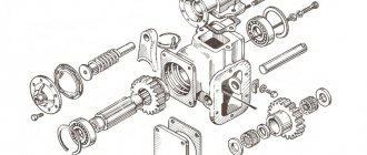
Composition of the RCP
According to the standards, the ZIL-131 RCP consists of the following list of structural elements:
According to the connection diagram, in the crankcase on the pistons there is a drive shaft with a gear and a ring gear installed to start the 5th speed mode. The crankcase is manufactured using gray cast iron with a closed system ventilation.
The material from which the valves are made is heat-resistant steel, which allows them to easily withstand any load.
When a car is driving on ice, activating the front-wheel drive axle is a necessary action. If this system action does not occur, it is worth checking the energy supply to the machine and the condition of the valves.
The control valve cover has a breather on top, and a drain and control-fill compartment on the bottom. A pneumatic chamber and seals in the shaft piston caps are securely attached to the outer panel of the crankcase. Inside the crankcase there is a component that switches the high-speed driving modes.
Features of electrical equipment
The car used the following, traditional for the domestic automobile industry:
- Single-wire circuit, where the role of the second wire is played by the metal body of the car;
- All electrical equipment is designed for 12 V;
- The starter operates on 24 V (a second battery is installed for this purpose);
- The main circuits are protected by fuses;
- As a basis, according to the unification of parts, the electrical wiring of ZIL 4331, the successor to ZIL 130, was used.
The factory instructions indicated the catalog numbers of the parts used
Features of cabin wiring
Having inherited the high cabin from the “big” brothers, the designers also used the interior wiring diagram of the ZIL Bychok without any special changes.
It allowed:
- reduce assembly costs;
- and for consumers - an acceptable price was offered for a “delivery” city truck.
Photo of the cabin, unified with older models of previous years
The old cabin also inherited some of the “features” of its predecessor.
In this connection, the owners operating this car were forced to correct the shortcomings with their own hands, namely:
- The power of the electric washer pump was not enough, since water was first supplied to the right blade, then to the middle one, and only then to the driver's side wiper blade;
- additional insertion of two nozzles into the hood solved the problem.
Dashboard
The main difficulties in operation arise in the work:
- ignition switch;
- main switch (located behind the battery box).
The instrument panel used upgraded wiring ZIL 4331
Scheme
ZIL-131 has several RCP schemes:
- with differential drive;
- blocked drive;
- mixed.
The schemes have some differences:
- A gearbox with a blocked drive promotes the simultaneous rotation of all drives, due to which the moment of force is distributed in accordance with the resistance force.
- If the manual gearbox has a differential drive, the output shafts have different angular rotation speeds. It is also called interaxle.
- RCPs with mixed drives include half of the driven shafts with the same angular rotation speed and the second half, which uses the interaxle principle. These also include boxes with a locked differential.
Based on the above, we can conclude that power is directed from the control gearbox to:
- one front and a pair of rear axles;
- a pair of front and a pair of rear axles;
- driving wheels of the sides of the machine.
Connecting the vehicle exhaust system
To connect the exhaust pipe to a diesel engine you must:
-muffle one lower branch of the exhaust pipe on the muffler; welding machine
-cut off the guide with the flange on the right branch of the exhaust pipe;
-insert a pipe (about 300 mm long) between the guide with a flange and the right pipe and weld it (you can use the left branch of the standard exhaust pipe);
- connect the modified right branch of the exhaust pipe to the diesel engine and muffler.
Malfunctions and ways to eliminate them
In most cases, RCP malfunction can be prevented or eliminated at an early stage. This is facilitated by regular inspections before the upcoming trip.
- Extraneous noise in the box. Indicates that some parts may be destroyed. To fix it, you need to disassemble the box and replace faulty structural elements.
- Random gear shifting. This indicates wear on the teeth of the carriage or the ring gears on the wheels. To eliminate them, they need to be replaced.
- Oil leakage occurs. Indicates wear of the sealing collars or rupture of the membrane in the pneumatic chamber. To fix it, you need to replace the faulty parts.
- There is a violation of the control rod adjustment. Indicates wear on the pins and traction forks. It is necessary to adjust the rods and replace the pins.
Source
Connecting the clutch drive
To connect the clutch drive, it is necessary to change the clutch release fork if there is no lever with splines.
The clutch drive connection is similar to the standard engine. key 14x17, 22x24
Clutch adjustment (Fig. 11):
-the working stroke of the pedal should be equal to 130-150 mm, which corresponds to the working stroke of the release bearing equal to 11 mm.
-free travel of the pedal is 35-50 mm, which provides a gap of 3-4 mm between the clutch release bearing and the levers (petals) of the clutch pressure plate.
The full travel of the clutch pedal is 180 mm.
Due to the fact that a diesel engine starter consumes more current (compared to a carburetor engine starter) to reduce the voltage drop on the wires and provide higher cranking speeds for the starter when
When starting, it is necessary to replace the wires connecting the batteries with the starter and the ground switch with thicker ones (with a cross-section of 50 mm2). In addition, the wires connecting the starter relay “K7” to the starter must be replaced; these wires must have a cross-section of 4 mm2.
The batteries must also be replaced with TWO batteries connected in parallel with a capacity of at least 88 Ah and a current in starter mode of 395A.
General view of the electrical circuit for connecting the motor (Fig. 12a, 12b).
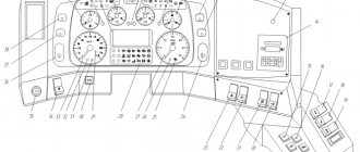
Information about the state of the vehicle's systems and components is concentrated on the instrument panel in the form of indicators and warning lights with certain symbols.
The location of controls and signaling devices in the cab of ZIL vehicles is shown in Fig. 1-3.
Some differences in controls are due to differences in vehicle design. For example, on ZIL-431410 vehicles with MTP or a single-circuit brake drive, different controls for the parking brake system are used.
The difference in the design of instrument panels and panels is associated with the use of new lighting devices and switching equipment in the electrical equipment system. This requires placing the fuse box on the instrument panel within easy reach of the driver. On cars in which the battery casing is heated, a heating damper control knob is installed between the driver and passenger seats, and an air temperature indicator in the casing is located on the instrument panel. When the handle is pulled up, the heating is on, when it is lowered, it is off. The intermediate position of the handle secures the ball along the teeth of the rod.
Rice. 1. Controls and signaling devices in the cabin of a car of the ZIL-431410 family with MTP: 1 - air temperature indicator in the battery casing; 2 — steering wheel; 3 — speedometer; 4 — engine emergency indicator; 5 - combined light switch; 6 — instrument cluster (pressure gauge; indicators of coolant temperature, fuel level, oil pressure, battery current, reserve fuel level indicators); 7 — rheostat for instrument lighting; 8 — pneumatic valve handle for windshield wiper control; 9 — control handle for the damper in the cabin heater duct; 10 — emergency alarm switch; 11 — fuse block; 12 — door lock handle; 13 — window lifter handle; 14 — heater damper control handle; 15 — gear shift lever; 16 — carburetor throttle control handle; 17 — carburetor choke control handle; 18 — control knob for the battery heating damper; 19 — valve handle of the parking brake system; 20 — throttle valve control pedal; 21 — pedal of the service brake system; 22 — clutch pedal; 23 — ignition and starter switch; 24 — windshield washer pedal; 25 — radiator shutter control handle; 26 — battery switch; 27 — valve button for the emergency brake release system; 28 — fuel level indicator sensor switch; 29 — controlled headlight switch; 30 - switch for road train lights; 31 — fan switch; 32 — fog lamp switch; 33 — switch for operating modes of the electric motor of the cabin heater; 34 — cabin light switch; 35 — indicator lamp check switch; 36 — pressure drop indicator in the front circuit of the service brake system; 37 — signaling device for turning on the tractor’s direction indicators; 38 — pressure drop indicator in the rear circuit of the service brake system; 39 — turn signal indicator; 40 — indicator of pressure drop in the parking and spare brake systems and control of the trailer brake mechanisms; 41 — signaling device for turning on the lights of a road train; 42 – signaling devices for turning on the parking brake system
To clean the windshield from dirt, a windshield wiper control valve is installed on the instrument panel, and a windshield washer pedal is installed on the cabin floor to the left of the steering column.
When the windshield wiper control knob is rotated to the left (counterclockwise), the intensity of the wiper operation increases, and when rotated to the right it decreases. The windshield wiper is turned off by rotating the pneumatic valve handle to the right until the air supply stops.
A drive for controlling the position of the engine cooling radiator shutter is attached to the left wall of the cabin under the instrument panel. The blinds are closed by pulling the radiator blind control handle all the way. The drive mechanism has fixed positions in which the handle can be installed if the blinds need to be partially opened.
The driver assesses the road situation on the sides behind the car cabin from his workplace through the rear side-view mirrors. Correct adjustment of the position of the mirrors means that the driver, from his seat in the working position, should see through both mirrors the space on the road on both sides along the sides, including the trailer (semi-trailer).
The controls also include an audible signal installed in the cab. The sound signal turns on automatically from the sensors of the multi-circuit brake system when the receivers are not completely filled and works with the light alarm. On ZIL-131N vehicles, the sound signal, in the case of transporting people, is activated by a button located on the platform.
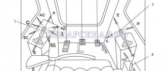
Rice. 2. Controls in the cab of the ZIL-131N car: 1 - pedal of the service brake system; 2 — foot light switch; 3 — windshield washer pedal; 4 — clutch pedal; 5 — radiator shutter control handle; 6 — windshield washer nozzle; 7 – direction indicator switch; 8 — gear shift lever; 9 — heater damper handle; 10 — transfer case lever; 11 — hatch of the winch activation lever; 12 — lever of the parking brake system; 13 — control handle for the battery heating damper; 14 — battery switch; 15 — lever for stopping the longitudinal movement of the seat; 16 — throttle valve control pedal; 17 — pneumatic signal button
Rice. 3. Controls and signaling devices in the cabin of ZIL vehicles models 131N and 431410 without MTP: 1 - tire pressure gauge; 2 — speedometer; 3 — headlight high beam signal; 4 — instrument cluster (indicators of battery current, coolant temperature, fuel quantity, engine oil pressure); 5 — front drive axle drive activation indicator; 6 — two-pointer pressure gauge of the pneumatic system; 7 — air temperature indicator in the battery casing; 8 — windshield washer nozzle; 9 — cockpit canopy; 10 — cabin light switch; 11 — switch for forced activation of the front axle drive; 12 — switch for the electric motor of the cabin heater; 13 — fog lamp switch; 14, 15 — push-button switch and controlled headlight switch; 16 — heater hood flap control handle; 17 — switch for identification lights of the road train; 13 — handle of the windshield wiper control valve; 19 — fuel level indicator switch; 20 — cabin fan switch; 21 — carburetor throttle control handle; 22 — lamp switch; 23 — carburetor choke control handle; 24 - central light switch; 25 — power take-off indicator; 26 — emergency engine oil pressure indicator; 27 — power take-off switch; 28 — turn signal indicator; 29 — coolant overheat indicator; 30 — ignition and starter switch; 31 — tire pressure control valve lever
On the steering column, under the steering wheel, at a distance accessible to the driver’s fingers, there is a combination light switch 5. It combines the controls for the devices most necessary when the car is moving: the headlight and side lamp switches, the electric and pneumatic horn switches, and the turn signal switch.
In the cabin of vehicles operating on gas fuel, there is a pressure gauge for monitoring gas pressure, as well as levers and buttons for controlling the operation of gas equipment and switching the supply of gasoline or gas fuel.
On specialized vehicles, devices for monitoring the operation of special organs and installation controls are mounted in the cab.
To facilitate the use of all instruments and vehicle controls, instruction signs are installed in the cab in accessible places for viewing.
Rice. 4. Controls and signaling devices in the cabin of the ZIL-133GYA vehicle: 1 - steering wheel; 2 — tachometer; 3 - combination switch; 4 — fuel level indicator; 5 — coolant temperature indicator; 6 — speedometer; 7 — battery current indicator; 8 — oil pressure indicator; 9, 10 — pressure gauges; 11 — signaling devices for electric torch heater, direction indicators, identification lights of the road train, center differential locking mechanism, parking and spare brake systems, pressure drop in the drive circuits of the brake mechanisms of the wheels of the rear bogie and the wheels of the front axle); 12 — block of switches and switches (fog lights and low beam headlights, road train lights and cab ceiling, electric motor operating modes); 13 alarm system switch; 14 — handle for manual control of fuel supply; 15 — engine stop rod handle; 16 — heater channel damper handle; 17 — handle of the windshield wiper control valve; 18 — rheostat for instrument lighting; 19 — electric torch heater switch; 20 — switch for electrical equipment and starter; 21 — cover of the fuse box and glove box; 22 — heater damper lever; 23 — fuel pedal travel limiter; 24 — fuel pedal; 25 — pedal of the service brake system; 26 clutch pedal; 27 valve handle of the parking brake system; 28 gear shift lever; 29 — gear switch in the divider; 30 — button for turning on the auxiliary brake system; 31 — emergency brake release button; 32 — handle for turning on the center differential locking mechanism; 33 — windshield washer pedal; 34 — radiator shutter handle