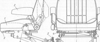
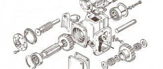
Gearbox assembly
Upper shaft assembly
Install shaft 1 (
) into the fixture with the keyway surface facing up.
Heat roller bearing 2 (inner ring) and install it on the shaft until it touches the shoulder. Turn the shaft over. Install ring 3 on the shaft. Press guide pin 20 all the way into the blind hole of the spline cavity for convenience and correct alignment of the grooves with the removed spline in couplings and bushings with a lubricant supply channel in the clamp. Install bushing 24, reverse gear 4, clutch 5, clutch 23, bushing 6, normal gear 7, clutch 22, clutch 8, bushing 21, fast gear 9, bushing 10 onto the shaft.
Install the lubricant supply clamp 12 with spring 11 on shaft 1 with the flat facing the lower shaft (for first-production machines). Install the oil pump drive gear 13, bushing 14 and bushing 19. Slide the gears and bushings until they stop and install the pack of shims 18 so as to ensure a gap A = 0.05...0.3 mm between bushing 19 and roller bearing 15. The shims are 2 thick .0 mm install on both sides of the bag. Heat roller bearing 15 and install it on the shaft. Put on lock washer 17. Tighten the assembled shaft with nut 16. The tightening torque of the nut is 450... 550 N• m (45...55 kgf m). Bend washer 17 onto the edge of the nut. With the assembled shaft, the gears should rotate freely on the bushings, and the couplings should move without jamming.
Assembling the first intermediate shaft
Install shaft 16 (
) into the fixture with the cylindrical surface of the large diameter facing up, heat roller bearing 1 and install it on the shaft. Turn the shaft over and install the parts on it: bushing 15, gears 2, 3, 4, ring 14.
Install retaining ring 5 into the groove of gear 7 and install bearing 13. Place the gear with the bearing on the shaft. Press the bearing into ring 14 until it stops. Install spacer 6, press in second bearing 13 and install retaining ring 8. Place ring 12. Heat roller bearing 9 and install on the shaft. Install lock washer 10, screw nut 11 with the machined end to the washer and lock it. The tightening torque of the nut is 450...550 Nm (45...55 kgf-m).
Assembling the second intermediate shaft
Install shaft 1 (
) into the fixture with the threaded end down, heat the roller bearing 9 and install it on the shaft. Put on the retaining ring 10. Turn the shaft over and install on it: gear 8, bushing 11, gear 7, gear 6, bushing 5, gear 4, gear 3.
Move the gears and bushings until they stop, install the pack of adjusting shims 12, ensuring a gap A = 0.05...0.3 mm between the end of gear 3 and the end of the inner ring of roller bearing 2. Install shims 2.0 mm thick on both sides of the pack. Heat bearing 2 and install it on the shaft.
Lower Shaft Assembly
Install shaft 1 vertically into the fixture with the bevel gear facing down. Install the inner ring of the roller bearing 15 onto the shaft until it stops against the collar and bushing 14. Press in the guide pins 18 (
) and 20 until it stops in the blind holes of the spline cavity of the lower shaft. The pins are installed for convenience and correct alignment of the grooves with the removed spline in couplings and bushings with lubricant supply holes in the lower shaft. Install bushing 16, second gear gear 13, clutch 12, clutch 17, bushing 11, first gear gear 10, spacer 9, bushing 8, third gear gear 7, clutch 5, clutch 6, bushing 4, fourth gear gear 19 onto the shaft, ring 21 and bushing 3.
Install the pack of adjusting shims 22 so as to ensure a gap A = 0.05...0.3 mm between the ends of the bushing 3 and the roller bearing ring 2.
Place 2.0 mm thick spacers on both sides of the bag. Heat roller bearing 2 and install it on the shaft.
On the assembled shaft, the gears should rotate freely on the bushings, and the clutches should switch freely. Install the lower shaft complete with the main gear bevel gear tested for tooth engagement. Disassembly of this conical pair is not permitted. The large bevel gear number is stamped on the gearbox housing.
Assembling shafts with front cover
Install the upper shaft 4 (
) of the gearbox into the device so that the distance from the end of the teeth of gear 7 ( ) to plane A of the device (front cover) is (126 ± 0.06) mm. Set the size (126±0.06) mm using a template. The specified size ensures distance A=(126±0.5) mm in the assembled gearbox (
) from the end of gear 7 ( ) to the inner end of the front cover.
Install the first intermediate shaft 2 ( ) in the device so that the protrusion of the ends of the teeth of gear 7 ( ) of the upper shaft in relation to the ends of the teeth of gear 2 (see Fig. 218) of the first intermediate shaft is (2 ± 0.5) mm. Install the shafts into the fixture to the specified dimensions by rotating handles 8 ( ).
Install the second intermediate shaft 5 into the fixture so that the gap between the ends of gear 2 ( ) of the first intermediate shaft and gear 6 ( ) of the second intermediate shaft is within (4±0.5) mm. Install the lower shaft 6 ( ) into the fixture.
Sling and install the front cover 3 of the gearbox onto the pins 1 and the plane of the device. Press the cover with clamps 7.
First install package E ( ) of split adjusting shims on the flange of the housing 10 bearings of the upper shaft. Diametrically spaced split gaskets must be of the same thickness.
Place ring 33 and rubber sealing ring 32 onto bearing housing 10 and install the housing into the gearbox cover. Press the outer ring of the roller bearing into the housing shoulder until it stops.
Heat the ball bearing and press it onto shaft 12 until it touches the roller bearing with the number on the ring facing up. Install oil deflector 17 and key 15 on the shaft. Lubricate the gasket with “Sealant” varnish on both sides and install it on the bearing housing flange.
Install cover 16 and secure it together with the bearing housing with bolts and spring washers. Heat flange 13 to a temperature of 523…543 K (250…270 °C) and press it onto the shaft. Screw nut 11 with left-hand thread onto the shaft until it stops at flange 13, screw in two locking bolts with spring washers. Check to see if the oil drain threads are catching on the bearing cap by turning the upper shaft.
Check size A = (126±0.5) mm, if necessary, install or remove adjusting shims E under the flange of the bearing housing to ensure the specified size. Install the package M of split shims onto the flange of the bearing housing 9.
Place ring 33 and rubber sealing ring 32 onto bearing housing 9 and install the housing into the gearbox cover. Press the outer ring of the roller bearing until it stops into the housing shoulder with the number on the ring facing up. Heat the ball bearing and press it onto shaft 26 until it touches the roller bearing with the number on the ring facing up. Install the lock washer with the inner tendril into the keyway of the shaft, screw the nut 8 with the machined end to the washer and bend the ends of the washer on the edge of the nut. Lubricate the gasket with Sealant varnish on both sides and install it on the bearing housing flange. Install the cover and secure it together with the bearing housing with bolts and spring washers. Check the size (2±0.5) mm and, if necessary, add or remove spacers in the M package.
Install package K of split shims onto the flange of the 6 bearing housing.
Place ring 33 and rubber sealing ring 32 onto bearing housing 6 and install the housing into the gearbox cover. Press in the outer ring. roller bearing into housing 6 until it stops at the housing shoulder with the number on the ring facing up. Heat the ball bearing in an oil bath and press it onto shaft 29 until it stops against the roller bearing with the number on the ring facing up.
Install the lock washer with the inner tendril into the keyway of the shaft, screw the nut 7 with the machined end to the washer and bend the ends of the washer onto the edge of the nut. Lubricate the gasket with “Sealant” varnish on both sides and install it on the housing flange 6. Install the cover on the gasket and secure it together with the bearing housing with bolts and spring washers.
Check the dimensions (4±0.5) mm and, if necessary, add or subtract the number of spacers in package K.
In transmissions on tractors of the latest production, split shim packs E, M and K are not used. The dimensions between the ends of the shaft gears are provided structurally.
Install the package T of split adjusting shims onto the flange of the lower shaft bearing housing 31.
Place ring 33 and rubber sealing ring 32 onto housing 4 and install it into gearbox cover 3. Press the outer ring of the roller bearing into the shoulder of the bearing housing until it stops. Heat the ball bearing in an oil bath and press it onto the shaft until it stops against the roller bearing with the number on the ring facing up. Install the washer with the inner tendril into the keyway, screw nut 5 with the machined end to the washer and bend the ends of the washer onto the edge of the nut. The rotation of the shafts must be free, without jamming. The thickness of the package of 7 gaskets is finally established by adjusting the size C = (83.9 ± 0.1) mm ( ).
Gearbox housing assembly
Place gearbox housing 1 on a stand or wooden floor. Lubricate the seats for the roller bearings in the gearbox housing with transmission oil. Install the outer rings of roller bearings 22, 24, 28, 30 into the housing holes, placing the slots for the stoppers opposite the holes in the housing. Install the stopper 20 into the hole in the gearbox housing so that it fits into the bearing seat 22.
When installing the stopper, do not use much force so as not to deform the outer ring of the roller bearing with the stopper.
Press plug 19 into the hole until it stops in the housing socket. The stopper should not rest against the stopper. Press in the bearing stoppers of the remaining shafts in the same way. Place O-ring 23 onto cover 25 and install it into the gearbox housing. Install ring 27 into the housing groove. Press into housing 1 (
) pins 2 and 4.
Screw in the studs, place a gasket coated with “Sealant” varnish on both sides, and install cover 25 (if it was removed), securing it with nuts and washers. Place a copper-asbestos and rubber ring onto the magnetic plug 24. Screw the plug into the hole in the cover 25. Press it into the body 1 (
) sleeve 22 with balls 21 assembled.
Assembling the front cover with the gearbox housing
Install the gearbox housing onto the fixture (
) with the mating surface down and secure.
Lubricate the gasket on both sides with “Sealant” varnish and install it on the housing flange. Install cover 3 ( ) assembled with the shafts into the housing so that pins 2 of housing 1 enter the holes in cover 3. Insert spring 18 of the upper shaft clamp into the hole in the housing. Body 1 and cover 3 must have the same number.
Secure cover 3 to the body with bolts and washers. Check shaft rotation manually. The rotation of the shafts must be free, without jamming. Check if there are any gaps in the gear mesh. Meshing of the teeth of any pair of gears without clearance is not allowed. Turn the gearbox in the device and set the lower shaft 31 to size C = (83.9 ± 0.1) mm between the end of the shaft and the plane of the gearbox housing using split gaskets T installed under the housing flange 4. Measure the size with the shaft shifted inward gearboxes If the bevel gear is installed incorrectly, the bevel pair may be destroyed during operation.
Lubricate the gasket with “Sealant” varnish and install 4 bearings on the housing. Screw the grease supply fitting into cover 21 ( ). Install cover 21 with the screwed fitting onto the gasket and, moving within the gap between the bolts and holes, find a position where when the lower shaft rotates, the fitting does not touch the lower shaft. In this position, secure the cover with bolts. Screw two pins into the holes in the front cover. Place tripod 22 on the studs and secure with nuts.
Installing Shift Shafts, Forks and Shanks
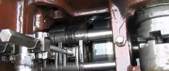
Turn the gearbox housing 1 ( ) so that the hatches for the shift mechanisms face upwards. Install the fork 29 into the annular groove of the upper shaft engagement clutch 32. Install the roller 28 into the body, passing it through the holes of the fork 29, and install the shank 27 on it.
Install the second bushing 25 into the annular groove of the upper shaft engagement clutch, the second roller 26 into the body, passing it through the hole of the fork 25, onto the shaft - shank 24. Secure the shanks to the flats of the rollers with stoppers.
Secure with wedges 34 on the flats of the fork rollers 25 and 29 with the outer gear coupling centrally located (the outer gear coupling should not hang over the inner one) in the neutral position of the roller 26 (the clamps 31 are installed in the middle groove on the rollers) and lock the nuts with a locking plate. Dimension B ( ) should be equal to (21.5 ± 0.8) mm. Manually check the movement of the rollers in the housing. The rollers must move freely. When moving one roller, the other must be securely locked with a ball lock.
Press in plug 23 ( ). Install covers 30 covering the ends of the gear shift rollers, using adjusting shims to maintain a gap of A = 0.3 mm between the cover and the ends of the rollers in the on position. Lack of clearance does not ensure gear engagement. If the gap is insufficient or exceeds the specified value, spontaneous gear shifting occurs under load. Install the forks and rollers for the lower shaft 33 in the same way. Install the grease supply fitting to the upper shaft. Install the oil pump if it was removed.
Assembling the left gear shift mechanism
Install spacer 3 ( ) complete with cover 2 on the table. Insert the roller 19 into the holes of the spacer 3 and the hole of the lever 20. Insert springs 17 into the blind holes of the spacer, install the long spring on the outside of the gearbox. Place ring 6, gaskets and inner flange 7. Press pin 16 into lever 11.
Install lever 11 into the inner flange 7 and the blind hole of the lever 20. Put on the gasket and the second inner flange 8. Install the outer flange 15 on the gasket and secure with bolts and washers. Install the O-ring 9, the cover 14 of the ball flange 15, the cap 13 and secure with a cotter pin.
Screw handle 12 onto the end of the lever. The assembly of the right switching mechanism is similar to the assembly of the left one, except for the installation of the VK-403 switch. Switch installation sequence: install into the recess of the threaded hole (
) rubber ring 7, locking plate 2, adjusting shims P (no more than eight pieces), use them to adjust the gap of 0.3...0.5 mm between the end of the switch and the cylindrical surface of the roller 6. Screw the switch until it stops and lock it with the plate.
Place the switching mechanism with a spacer on the cover pins and a gasket lubricated with “Sealant” varnish, secure with bolts and washers.
Assembling the clamp housing with the roller
Insert the roller 13 ( ) into the hole in the housing 12. Place the oil seal 6 on the protruding end of the roller and press it into the housing 12 flush with the end of the housing. Place lever 7 on the end of the roller and align the groove of the roller with the hole in the lever. Install stopper 9 and secure with a nut and washer. When tightening the nut, tap stopper 9 on the large diameter end.
Insert tip 8 into the lever. Put on the washer and secure with a cotter pin. Similarly, assemble the clamp housing with the shaft for the left shift mechanism.
Place the thrust bar I, insert it into the recess on the roller 13 clamps and install the guide plate 10 with gaskets, lubricating them with “Sealant” varnish. Secure the housing of 12 clamps to the cover with bolts and spring washers. Press plug 14 into housing hole 12.
Installation of the gear shift mechanism
Screw the studs into the gearbox housing 1 ( ) and place a gasket coated on both sides with “Sealant” varnish. Install two clamps 31 into the slots so that they fit into the grooves of the rollers in the neutral position, as shown in the figure. The flats at the top of the clamps should be located forward along the tractor.
Install the switching mechanisms assemblies onto two studs and two pins of the gearbox housing and insert levers 20 into the grooves of the shanks. Secure the switching mechanism with nuts and spring washers. If necessary, replace seal 18.
Rice. 212. Caliber for setting the shift roller to the neutral position
With the levers 20 in the neutral position, using device 1 (Fig. 212), adjust roller 19 (29±1) mm from the end of the small boss of the spacer 2 ( ). Secure the lever through the side hatch with 20 bolts 5 and secure them with a locking plate. Place lock washer 4 and gasket on plug 5 ( ) and tighten until tight. Screw plugs 5 in the same way into the threaded holes of the remaining bosses. Install the right gear shift mechanism in the same way as installing the left gear shift mechanism.
The movement of the rollers with forks must be free, with clear fixation of the neutral and working positions. The rotation of the levers of the clamp rollers must be free, with the gear shift lever in the neutral position and in positions corresponding to the full engagement of any gear.
When the clamps are locked, movement of the gear shift rollers is not allowed, which must be ensured by adjusting the gap between the end of the clamp and the shaft using cardboard spacers 15 ( ) installed under the housing of the clamp roller. Glue ring 21 ( ) into the groove of the flange of the box body using 88NP glue. The outer end surface of the ring must be clean of glue.
Running in and testing the gearbox
Place the gearbox on the stand, fill the housing with 25 liters of tractor transmission oil (see operating instructions). Run in without load for two minutes in each gear, starting from the lowest. The rotation speed of the upper shaft of the gearbox should be 500...800 min-1.
During the break-in process, check the clutch shifts in all forward and reverse gears. Switching should occur freely, without jamming. During break-in, slight gear noise is allowed. Individual impacts, knocks and fractional rolls with increased noise are not allowed. The temperature in the gearbox after break-in should not exceed the ambient temperature by more than 50 °C. Oil leakage through the seals during break-in is not allowed.
After break-in, remove the gearbox from the stand, drain the oil and install it on a wooden floor. Cover the box bearings with parchment paper and drive wooden plugs into the grease inlet and outlet holes for the lower shaft and oil pump. Wash the oil receiver screen.
It is allowed to test the gearbox during testing of the tractor power transmission. When running the tractor, check the operation of the gear shift locking mechanism. The gearbox is run-in in all forward and reverse gears.
The movement of the rollers with forks should be easy, without jamming and with clear fixation of the neutral and working positions. The rotation of the clamp roller levers should be free, without jamming, in the neutral position of the gear shift lever and in positions corresponding to the full engagement of any gear.
Check if there is pressure in the transmission lubrication system when the transmission upper shaft rotates. If there is no pressure in the lubrication system, a ruby-colored light on the instrument panel lights up. Operating the tractor without pressure in the lubrication system is not allowed.
Specifications
Due to its special design, the T-130 tractor has a large supporting surface. This makes it possible to slightly remove and compact the top layers of soil when performing agricultural work. A tractor with high cross-country potential is capable of developing high traction force.
With a total mass of 14.32 tons, the T-130 exerts a pressure on the soil equivalent to 0.05 MPa. The model is equipped with a 140-horsepower diesel engine and an eight-speed gearbox.
Technical characteristics of the T-130 tractor:
| Characteristics | Indicators |
| Dimensions: | |
| - length | 5193 mm |
| - width | 2475 mm |
| - height | 3085 mm |
| - base | 2478 mm |
| - track | 1880 mm |
| Total weight | 14320 kg |
| Number of gears: | |
| — forward movement | 8 |
| Transmission | mechanical |
| Chassis type | crawler |
| Engine: | |
| - power | 140 hp |
| — number of cylinders | 4 |
| — specific fuel consumption g/kW*h | 244,3 (180) |
The video shows the T-130 tractor in action: