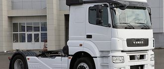
The Ural 4320 off-road truck has been produced with various modifications and changes from 1977 to the present day, mainly with diesel engines. During this time, the Urals underwent modernization several times. In this article you will find a detailed description of fuses and relays Ural 4320 with block diagrams and photographs, as well as a complete electrical wiring diagram.
The purpose of the elements in the blocks and their location may differ from those presented and depend on the year of manufacture and level of equipment of your Ural 4320.
"Ural"-4320, 5557: power take-off
The car's power take-off (PTO) is single-stage.
Fixed on the right side to the gearbox housing. Designed to drive auxiliary mechanisms. “Urals” are equipped with two types of PTOs: with a flange and a pump. The PTO should be turned on when the air pressure in the pneumatic system reaches 500 kPa (5 kgf/cm2). The clutch must be disengaged. Between the PTO and the flanges of the Ural-4320 gearbox housings there are adjusting gaskets, with the help of which the lateral clearance is adjusted based on the noise in the meshing of the gears. If it is necessary to replace the gaskets, their thickness must be maintained.
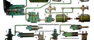
The power take-off can be controlled remotely. The control is pneumatic, which includes a control valve, a starting device, and air ducts. To remotely turn on the PTO, there is a control valve mounted on a bracket to the right of the driver in the cockpit at the bottom of the dashboard. If the PTO is disabled, then the lever is at the top and the rod is in the right position. Under the action of a spring, the valve is pressed against the seat and air does not flow through the tap.
When the power take-off is turned on, the crane lever is moved to the lower position. The rod moving to the extreme left puts pressure on the valve and moves it away from the seat. Compressed air flows through air ducts into the diaphragm chamber of the switching device. Through the rod and fork, the diaphragm engages the driven shaft gear with the drive gear.
When the PTO is turned off, the valve lever is in the upper position. Under the action of the spring, the rod takes the extreme right position, moving away from the valve. The chamber of the vehicle gearbox switching device communicates with the atmosphere, air comes out of the chamber, and under the influence of a spring, the rod and fork disengage the driven shaft gear from the drive gear. In parallel with the release of air into the atmosphere, the valve is pressed against the seat under spring pressure and separates the valve openings (inlet and outlet).
"Ural"-4320, 5557: additional power take-off box
Power is taken from the input shaft of the machine's transfer case through a movable clutch. The power take-off is designed to drive the winch, as well as other devices and installations.
The additional power take-off box can operate in any gear, including neutral. To lubricate the shaft and gear bearings, a plunger pump is provided in the additional power take-off box. The pump includes a piston with a discharge valve, a safety valve and a housing. A piston with a connecting rod is located on the eccentric of the shaft. When the eccentric rotates, the piston moves forward.
To avoid excessive pressure when the rotation speed increases, the suction valve is made of a differential type and has a cylindrical spring. Oil is taken through a tube, which is connected to the oil bath of the transfer case of the machine, and supplied from the pump to the gear bearings through channels made in the primary shaft of the transfer case and the shaft. Some of the oil passes through the gaps, and thus the shaft bearings are lubricated.
In the driver's cabin, at the bottom right of the instrument panel, there is a control valve for remote activation of the additional power take-off box of the Ural-4320 vehicle. The faucet is mounted on a bracket. The control valve lever in the “off” position is fixed with a screw located on the valve bracket.
If the auxiliary power take-off box operates for a long time, there should not be excessive heating of the bearings of the power take-off shafts and the transfer case. If the heating is increased, this indicates a breakdown of the oil pump.
To check the operation of the pump, you should:
- tighten the parking brake handle all the way;
- Move the transfer case gear shift handle to the neutral position;
- turn off the winch; to do this, move the handle on the right side member of the frame down;
- Unscrew the plug in the pump housing;
- start the engine, turn on the additional power take-off box of the Ural-4320, 5557 car, turn on one of the gears,
- identify pump failure by closing the plug hole with your finger.
If the pump is working properly, then a pulsation is felt in the hole under the plug. It is prohibited to operate if the pump is faulty.
Source
Not available:
| № | Part code | Name | Part Information |
| 4320-3803022 | Stub | Quantity for URAL-43204-1111-70 URAL-43204-1153-70 URAL-4320-1958-70I 2 Model 4320 Group Instruments Subgroup Control lamps (Indicator lamps) Part number 022 | Not available |
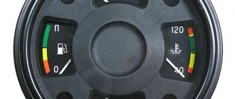
| 1921-3830010 | Two-pointer pressure gauge | Quantity for URAL-43204-1111-70 URAL-43204-1153-70 URAL-4320-1958-70I 1 Model 1921 Group Instruments Subgroup Pressure gauges Serial part number 010 | Not available |
| 4320Я5-3805013 | Left instrument panel | Quantity for URAL-43204-1111-70 URAL-43204-1153-70 URAL-4320-1958-70I 1 Model 4320Y5 Group Devices Subgroup Instrument panel Serial part number 013 | Not available |
| 33-3810010 | Pressure indicator in the engine lubrication system | Quantity for URAL-43204-1111-70 URAL-43204-1153-70 URAL-4320-1958-70I 1 Note Replacement is allowed Model 33 Group Instruments Subgroup Pressure gauges (oil pressure indicator) Serial part number 010 | Not available |
| 36-3807010 | Temperature indicator | Quantity for URAL-43204-1111-70 URAL-43204-1153-70 URAL-4320-1958-70I 1 Note Replacement is allowed Model 36 Group Instruments Subgroup Water temperature indicator receiver Serial part number 010 | Not available |
| 2212-3803-34 | Air filter clogged indicator | Quantity for URAL-43204-1111-70 URAL-43204-1153-70 URAL-4320-1958-70I 1 Note BDI | Not available |
| 2212-3803-17 | Engine preheating indicator | Quantity for URAL-43204-1111-70 URAL-43204-1153-70 URAL-4320-1958-70I 1 | Not available |
| А2С53218711 | Electronic tachometer | Quantity for URAL-43204-1111-70 URAL-43204-1153-70 URAL-4320-1958-70I 1 Model A2 Group Cabin front Subgroup 5321 Serial part number 871 | Not available |
| 4320Я5-3805031-10 | Left instrument panel | Quantity for URAL-43204-1111-70 URAL-43204-1153-70 URAL-4320-1958-70I 1 Model 4320Y5 Group Devices Subgroup Instrument panel Serial number of part 031 Additionally Not interchangeable with a part previously released under the same number | Not available |
| 220082-P29 | Screw M5-6ghx20 | Quantity for URAL-43204-1111-70 URAL-43204-1153-70 URAL-4320-1958-70I 13 Galvanizing and passivation coating (zinc with chromating) | Not available |
| 252269-P29 | Lock washer 6 | Quantity for URAL-43204-1111-70 URAL-43204-1153-70 URAL-4320-1958-70I 6 Galvanizing and passivation coating (zinc with chromating) | Not available |
| 4320Я5-3805012 | Right instrument panel | Quantity for URAL-43204-1111-70 URAL-43204-1153-70 URAL-4320-1958-70I 1 Model 4320Y5 Group Instruments Subgroup Instrument panel Serial part number 012 | Not available |
| А2С53194640 | Electronic speedometer | Quantity for URAL-43204-1111-70 URAL-43204-1153-70 URAL-4320-1958-70I 1 Model A2 Group Cabin front Subgroup 5319 Serial part number 464 | Not available |
| 2212-3803-16 | Battery charge indicator | Quantity for URAL-43204-1111-70 URAL-43204-1153-70 URAL-4320-1958-70I 1 | Not available |
| 11-3812010 | Voltage indicator | Quantity for URAL-43204-1111-70 URAL-43204-1153-70 URAL-4320-1958-70I 1 Model 11 Group Devices Subgroup 3812 Serial part number 010 | Not available |
| 2212-3803-28 | Headlight high beam indicator | Quantity for URAL-43204-1111-70 URAL-43204-1153-70 URAL-4320-1958-70I 1 | Not available |
| 4320Я5-3805030-10 | Right instrument panel | Quantity for URAL-43204-1111-70 URAL-43204-1153-70 URAL-4320-1958-70I 1 Model 4320Y5 Group Devices Subgroup Instrument panel Serial number of part 030 Additionally Not interchangeable with a part released earlier under the same number | Not available |
| 2411-3830010 | Tire pressure indicator | Quantity for URAL-43204-1111-70 URAL-43204-1153-70 URAL-4320-1958-70I 2 Model 2411 Group Instruments Subgroup Pressure gauges Serial part number 010 | Not available |
| 4320Я5-3805015 | Switch panel | Quantity for URAL-43204-1111-70 URAL-43204-1153-70 URAL-4320-1958-70I 1 Model 4320Y5 Group Instruments Subgroup Instrument panel Serial part number 015 | Not available |
| 41-3722-09 | Fuse box | Quantity for URAL-43204-1111-70 URAL-43204-1153-70 URAL-4320-1958-70I 2 | Not available |
| 201418-P29 | Bolt M6-6gх16 | Quantity for URAL-43204-1111-70 URAL-43204-1153-70 URAL-4320-1958-70I 4 Galvanizing and passivation coating (zinc with chromating) | Not available |
| 252003-P29 | Washer 5 | Quantity for URAL-43204-1111-70 URAL-43204-1153-70 URAL-4320-1958-70I 6 Galvanizing and passivation coating (zinc with chromating) | Not available |
| 252153-P2 | Spring washer 5 | Quantity for URAL-43204-1111-70 URAL-43204-1153-70 URAL-4320-1958-70I 4 Coating phosphating and oiling | Not available |
| 4320M-3722011 | Fuse box bracket | Quantity for URAL-43204-1111-70 URAL-43204-1153-70 URAL-4320-1958-70I 1 Model 4320M Group Electrical equipment Subgroup Fuses (electrical circuits) Part number 011 | Not available |
| 375-3505076-12 | Stub | Quantity for URAL-43204-1111-70 URAL-43204-1153-70 URAL-4320-1958-70I 2 Model 375 Group Brakes Subgroup Main brake cylinder (hydraulic brakes) Part serial number 076 Additionally Not interchangeable with a part previously produced under the same number | Not available |
| 220081-P29 | Screw M5-6gx8 | Quantity for URAL-43204-1111-70 URAL-43204-1153-70 URAL-4320-1958-70I 2 Galvanizing and passivation coating (zinc with chromating) | Not available |
| 245-3710-01 | Hazard switch | Quantity for URAL-43204-1111-70 URAL-43204-1153-70 URAL-4320-1958-70I 1 Note Replacement is allowed | Not available |
| P305-3709010-0 | Light switch | Quantity for URAL-43204-1111-70 URAL-43204-1153-70 URAL-4320-1958-70I 1 Model P305 Group Electrical equipment Subgroup Electrical switches (central light switch) Part serial number 010 | Not available |
| 375-3709012 | Switch handle assembly | Quantity for URAL-43204-1111-70 URAL-43204-1153-70 URAL-4320-1958-70I 1 Model 375 Group Electrical equipment Subgroup Electrical switches (central light switch) Part number 012 | Not available |
| 4320Я5-3805016 | Additional switch panel | Quantity for URAL-43204-1111-70 URAL-43204-1153-70 URAL-4320-1958-70I 1 Model 4320Y5 Group Instruments Subgroup Instrument panel Serial part number 016 | Not available |
| PD511E-3803010-U-HL | Right indicator lamp block | Quantity for URAL-43204-1111-70 URAL-43204-1153-70 URAL-4320-1958-70I 1 Model PD511E Group Devices Subgroup Control lamps (Indicator lamps) Part serial number 010 Additionally Interchangeable with parts previously released under the same number | Not available |
| 11-3704000-01 | Push-button switch | Quantity for URAL-43204-1111-70 URAL-43204-1153-70 URAL-4320-1958-70I 1 Model 11 Group Electrical equipment Subgroup Ignition switch (ignition switch) Part serial number 000 | Not available |
| VK343-3709-01-08 | Light switch | Quantity for URAL-43204-1111-70 URAL-43204-1153-70 URAL-4320-1958-70I 1 | Not available |
| 4320-3710014 | Frame | Quantity for URAL-43204-1111-70 URAL-43204-1153-70 URAL-4320-1958-70I 1 Model 4320 Group Electrical equipment Subgroup Electrical switches (foot light switch) Part number 014 | Not available |
| 43202-5301214 | Stub | Quantity for URAL-43204-1111-70 URAL-43204-1153-70 URAL-4320-1958-70I 1 Model 43202 Group Cabin front Subgroup Frame and front panels Serial part number 214 | Not available |
| PD512E-3803010-U-HL | Left indicator lamp block | Quantity for URAL-43204-1111-70 URAL-43204-1153-70 URAL-4320-1958-70I 1 Model PD512E Group Devices Subgroup Control lamps (Indicator lamps) Part serial number 010 Additionally Interchangeable with parts previously released under the same number | Not available |
| 4334196EY | Cork | Quantity for URAL-43204-1111-70 URAL-43204-1153-70 URAL-4320-1958-70I 1 Subgroup 4334 Serial number of part 196 Additionally Interchangeable with part released earlier under the same number | Not available |
| 2212-3803-85 | Engine control unit diagnostic switch indicator | Quantity for URAL-43204-1111-70 URAL-43204-1153-70 URAL-4320-1958-70I 1 Note Replacement is allowed | Not available |
| 2212-3803-20 | Air filter clogged indicator | Quantity for URAL-43204-1111-70 URAL-43204-1153-70 URAL-4320-1958-70I 1 | Not available |
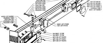
Design of the Ural car power take-off
Power take-off (PTO) - single-stage, attached to the gearbox housing on the right side and is designed to drive auxiliary units
The box is manufactured in two versions: with a pump (Fig. 1) and a flange (Fig. 2).
Turn on the power take-off when the air pressure in the car's pneumatic system is at least 500 kPa (5 kgf/cm 2) and the clutch is disengaged.
Adjusting shims are installed between the flanges of the gearbox housing and the power take-off, with the help of which the lateral clearance in the gear mesh (for noise) is adjusted.
If it is necessary to replace the gaskets with new ones, their thickness must be maintained.
The power take-off control is pneumatic and consists of a control valve, a switching mechanism and air ducts.
Additional power take-off
Power is taken off from the primary shaft of the transfer case through movable coupling 2 (Fig. 4) and is intended to drive the winch.
Operation of the auxiliary power take-off is possible when the transfer case gear clutch is in neutral position.
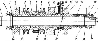
To lubricate the gear and shaft bearings, a plunger pump is installed in the additional power take-off box.
The pump consists of a piston 17 with a discharge valve 18, a safety valve 20 and a housing 22.
The piston with connecting rod is mounted on the eccentric of shaft 3 and moves progressively when it rotates.
To prevent excessive pressure as the rotation speed increases, the suction valve is a differential type with a coil spring.
The oil is taken through a tube 1 connected to the transfer case oil bath, and from the pump it goes to the gear bearings through channels made in shaft 3 and in the transfer case input shaft.
Some of the oil penetrates through the gaps and lubricates the shaft bearings.
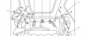
To ensure remote activation of the auxiliary power take-off box in the cabin, to the right of the driver on the lower edge of the instrument panel, a control valve is installed on the bracket.
When the auxiliary power take-off box is turned off, lever 8 (see Fig. 3) is in the upper position, rod 7 is in the right position.
The valve, under the action of its spring, is pressed against seat 4 and air does not flow through the tap.
When the handle is moved to the lower position, rod 7 moves to the extreme left position, puts pressure on the valve and moves it away from the seat.
Compressed air enters the switching chamber and turns on the additional power take-off box, compressing spring 8 (see Fig. 4).
When the auxiliary power take-off box is turned off, the crane lever is moved to the upper position.
The rod, under the action of the spring, moves to the extreme forward position, breaking away from the valve.
Through a hole in the rod, the switching chamber of the box communicates with the atmosphere, air is released from the chamber, and the spring turns off the box.
Simultaneously with the release of air into the atmosphere, the valve is pressed against the seat under the action of a spring and separates the inlet and outlet openings of the valve.
The control valve lever is fixed in the off position with a screw installed on the valve bracket.
During prolonged operation of the auxiliary power take-off box, there should be no increased heating of the bearings of the transfer case input shaft and the power take-off shaft.
Increased heating indicates a malfunction in the oil pump.
Check the serviceability of the pump with two people.
To check the pump operation:
— tighten the parking brake lever as far as possible;
— set the transfer case gear lever to the neutral position;
— turn off the winch by lowering the lever on the right side member of the frame;
— unscrew plug 19 in the pump housing;
— start the engine, engage the auxiliary power take-off and one of the gears in the gearbox;
— determine the serviceability of the pump by closing the hole under the plug with your finger.
When the pump is working properly, you can feel the oil pulsating in the hole for the plug.
It is prohibited to work with a faulty pump.
Source
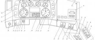
Fuse box
It is located in the instrument panel, behind the protective cover. On the cover of each block the current strength for which the fuses located under it is designed is indicated.
Scheme
Purpose
Upper block
- fog light chain
- headlight lamp circuit
- circuit of portable and engine compartment lamps, power circuit of control lamp units
- circuit of the cabin lamp, road train sign lights and brake light lamps
- heater motor and reversing light circuit
- power supply circuit for devices and buzzer
Bottom block
- left side light
- right side marker and instrument lighting
- low beam left headlight
- low beam right headlight
- left high beam headlight
- high beam right headlight
The remaining individual fuses are located under the hood (see diagram). For example, the heater power circuit is protected from short circuits by a 30 A bimetallic fuse 291.3722.
Description of modernized models
In later models, the fuse box itself is located in the same place, but made in a different form.
In some modernized Ural models, the fuse and relay box may be located in the panel on the right side, on the passenger side, behind a protective cover on which the current diagram will be printed.