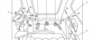
Controls and monitoring devices of the DT-75 tractor
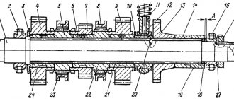
The cabin contains the main tractor controls and instruments for monitoring the operation of the main engine and electrical equipment. The remaining control levers for the main and starting engines are located on the left side of the engine and can only be used when the tractor is stopped. The starter of the starting engine is turned on using lever 10 (Fig. 1), moving it to the rearmost position. At the same time, the starter gear is engaged with the flywheel ring of the starting engine. Lever 11 engages the gear of the starting motor gearbox with the flywheel ring of the main engine. To do this, move the lever down and then return it up until the stopper locks. The clutch of the starting motor gearbox is turned on and off using lever 12 located on the front cover of the gearbox. When the lever is turned toward you (away from the engine), the clutch is turned on; when you turn it away from you (towards the engine), it is turned off.
To remove air from the engine power system, use the handle 14 of the hand pump. When lever 15 of the decompression mechanism is installed in the upper position, the air in all cylinders is not compressed (the valves are slightly open) and thereby makes it easier to turn the crankshaft. The cover 16 of the air pipe of the carburetor of the starting engine prevents dust from entering the carburetor. When the starting engine is not running, the pipe must always be closed with a lid.
The ignition of the starting engine is turned off by pressing button 17. The air damper of the carburetor of the starting engine is controlled by lever 18, and the throttle valve by lever 19. Before starting the engine, open valve 21 to supply fuel from the tank to the carburetor. When starting the main engine of the T-74 tractor, the fuel supply is increased using lever 34, and the engine of the DT-75 tractor is increased using lever 12 (Fig. 2), moving it to the upper position. When the engine is running, the amount of warm air entering the cabin of the T-74 tractor is controlled by handle 22 (see Fig. 1), and of the DT-75 tractor - using knob 8 (Fig. 2).
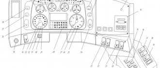
The operation of electrical equipment is checked using ammeter 23 (see Fig. 1). While the engine is running with a charged battery and the headlights are off, the ammeter needle should be near zero on the scale, deviating slightly to the right (towards the plus side). The oil pressure in the engine lubrication system is controlled by a pressure gauge 25, the temperature of the water leaving the cylinder head jacket is controlled by a remote thermometer 29, and the oil temperature in the crankcase is controlled by a remote thermometer 33. Normal oil pressure should be in the range of 3.0-3.5 kg/ cm2, normal oil temperature is 80-100° C, water temperature is 80-95° C. A pressure gauge is additionally installed on the control panel in the cab of the DT-75 tractor, indicating the oil pressure in the torque multiplier. The headlights are turned on using lever 26. When the fuse trips, to turn on the light, you must press the fuse button 24. The lighting on the instrument panel and the lampshade is turned on using lever 28. When the lever is in the middle position, the lamp and lampshade are off, when the lever is in the upper position, the instrument panel lamp is on, and when the lever is in the lower position, the lampshade is on. On the control instrument panel, switch 7 is installed to turn on the front headlights of the DT-75 tractor (Fig. 3) and switch 8 is installed to turn off the instrument panel light.
The cabin fan of the T-74 tractor is turned on using lever 27 (see Fig. 1), to do this it is turned up. The direction of the flow of fresh air into the cabin is regulated by the rotary visor 30. On the DT-75 tractor, the cabin fan is turned on by switch 1 (Fig. 4), installed in the upper right corner of the cabin and also intended to turn the cabin lamp on and off. Switch 2 of the right rear light and switch 3 of the left rear light are also installed there. On the T-74 tractor, switch 37 (see Fig. 1) for the rear lights is installed in the right rear corner. When the lever is moved up, the rear lights are turned on, and when it is moved down, the headlights of the trailed implements are turned on.
The windshield wiper of the front window of the cab is turned on with lever 31, the sound signal - with button 32. The transmissions of the T-74 and DT-75 tractors differ from each other, therefore the controls of these tractors are characterized by some features. On the T-74 tractor, gears are switched using levers / and 2. Lever 1 is used to change gear groups of the gearbox, and lever 2 is used to change gears in each group. The position of the handles of levers / and 2 when engaging each forward and reverse gear is shown in Figure 5. On the DT-75 tractor, gears are switched using lever 5 (see Fig. 2), the position of which when engaging each gear is shown in Figure 6. You can change gears only with the main clutch completely disengaged. The main clutch of the T-74 tractor is turned off with pedal 3 (see Fig. 1), pressing it, and of the DT-75 tractor with lever 6 (see Fig. 2), moving it forward. It is not recommended to keep the main clutch in the disengaged position for a long time. When braking the T-74 tractor, use pedals 4 and 5 (see Fig. 1), and when braking the tractor (T) (7) DT-75, use pedals 2 and 3 (see Fig. 2).
To make a turn, press the pedal on the side in which you want to turn the tractor. To hold the T-74 tractor in a braked position, press pedal 5 (see Fig. 1) and engage the latch o with the comb teeth. The T-74 tractor is turned using levers 35 and 36, and the DT-75 tractor is turned using levers 10 and 11 (see Fig. 2). When one of the levers is retracted to the rearmost position, the tractor turns towards the retracted lever. To turn the tractor sharply, after retracting the lever, press the brake pedal on the side in which the turn is being made. The power take-off shaft on the T-74 tractor is turned on by lever 8 (see Fig. 1), and on the DT-75 tractor by lever 4 (see Fig. 2). When the lever is placed in the rearmost position, the power take-off shaft is turned on, and in the forward position, it is turned off. The power take-off shaft may only be turned off and on when the main clutch is disengaged.
The hydraulic mounted system of the T-74 tractor is controlled using levers 7 (see Fig. 1), the DT-75 tractor is controlled by levers 9 (see Fig. 2). When the lever is installed in the uppermost position, the working parts of the implement rise. The middle position of the lever is “neutral”. When the levers are set to the lower position (after neutral), the implement is lowered. The lowest position of the lever is “floating”. You need to move the lever from the neutral position to the floating position quickly, without lingering in the “lowering” position. To raise the implement from the floating position, quickly move the lever to its highest position. The pump of the hydraulic mounted system of the DT-75 tractor is turned on using lever 14, moving it towards the radiator. The torque amplifier is controlled by lever 1. When you move the lever toward you, the torque amplifier is turned on. In the on position, the lever is locked with a latch located on the floor of the cabin.
Not available:
| № | Part code | Name | Part Information |
| 10-01 | Washer GOST 11371-78 | Quantity for DT-75 2 | Not available |
| 12-01 | Washer GOST 11371-68 | Quantity for DT-75 2 | Not available |
| 12-65G | Washer GOST 6402-70 | Quantity for DT-75 1 | Not available |
| 20-01 | Washer GOST 11371-78 | Quantity for DT-75 2 | Not available |
| 3.2Х18 | Cotter pin GOST 397-79 | Quantity for DT-75 1 | Not available |
| 4Х22 | Cotter pin GOST 397-79 | Quantity for DT-75 16 | Not available |
| 5Х28 | Cotter pin GOST 397-79 | Quantity for DT-75 1 | Not available |
| 6Х12Х45 | Axle GOST 9650-71 | Quantity for DT-75 1 | Not available |
| 77-38-228 | Finger | Quantity for DT-75 1 | Not available |
| 77-40-112 | Sleeve | Quantity for DT-75 1 | Not available |
| 77-40-161-1A | Adjustment clutch | Quantity for DT-75 1 | Not available |
| 77-40-188A | Spring | Quantity for DT-75 1 | Not available |
| 77-40-189A | Washer | Quantity for DT-75 3 | Not available |
| 77-40-194-1A | Spring | Quantity for DT-75 1 | Not available |
| 78-40-038 | Lever arm | Quantity for DT-75 1 | Not available |
| 78-40-044-2 | Traction | Quantity for DT-75 1 | Not available |
| 78-40-045-2 | Traction | Quantity for DT-75 1 | Not available |
| 78-40-216-01 | Clutch lever | Quantity for DT-75 1 | Not available |
| 78-40-222 | Lever arm | Quantity for DT-75 1 | Not available |
| 78-40-235 | Spring earring | Quantity for DT-75 1 | Not available |
| 78-40-324 | Axis | Quantity for DT-75 1 | Not available |
| 88-40-043 | Lever arm | Quantity for DT-75 1 | Not available |
| 88-40-044 | Drive traction | Quantity for DT-75 1 | Not available |
| 88-40-077 | Lever arm | Quantity for DT-75 1 | Not available |
| 88-40-087 | Gearbox traction | Quantity for DT-75 1 | Not available |
| 88-40-088 | Guide | Quantity for DT-75 1 | Not available |
| 88-40-318 | Video clip | Quantity for DT-75 1 | Not available |
| 88-40-319 | Roller finger | Quantity for DT-75 1 | Not available |
| 88-40-320-1 | Lever axis | Quantity for DT-75 1 | Not available |
| 88-40-336 | Fork | Quantity for DT-75 1 | Not available |
| 88-40-348 | Finger | Quantity for DT-75 1 | Not available |
| 88-40-363 | Gear traction shackle | Quantity for DT-75 1 | Not available |
| 88-40-364 | Traction | Quantity for DT-75 1 | Not available |
| 88-40-370 | Fork | Quantity for DT-75 1 | Not available |
| 88-40-371 | Fork | Quantity for DT-75 1 | Not available |
| 88-40-373 | Fork | Quantity for DT-75 1 | Not available |
| IBM10X30 | Screw GOST 17473-72 | Quantity for DT-75 2 | Not available |
| A40-18-01 | Finger | Quantity for DT-75 4 | Not available |
| M10 | Nut GOST 5915-70 | Not available | |
| М12-6gХ40 | Bolt GOST 7796-70 | Quantity for DT-75 1 | Not available |
| M12X1.25 | Nut GOST 5916-70 | Quantity for DT-75 1 | Not available |
| М12Х1,25ЛВ | Nut GOST 5916-70 | Quantity for DT-75 1 | Not available |
Charging circuit MTZ-80
This color diagram with a description shows what elements the charging system of the MTZ-80 tractor consists of.
- Generator, which is the main power source.
- Rechargeable lead-acid batteries act as a backup power source for the tractor engine.
- An indication lamp that lights up when the generator does not produce electric current when the ignition switch is turned on.
- A fuse box that protects an electrical circuit from a short circuit.
The generator and battery are connected with a “positive” wire, and the “minus” wire is output to the metal case.
Maintenance and repair
Maintenance of the electrical components of the MTZ-82 tractor consists of carrying out routine maintenance and checking the condition of cables, instruments and incandescent lamps. The batteries are wiped from dust and traces of electrolyte, the liquid level in the banks is checked, and recharging is performed. In the generator, the field windings are checked, as well as the rectifier unit and the windings on the stator.
The voltage regulator used on the tractor is equipped with a seasonal switch. The manufacturer recommends checking and adjusting the voltage value at the regulator output. The unit is configured on equipment or on a special stand.
The electric starter is serviced after 3000 hours of diesel engine operation. The electric motor is removed for disassembly, followed by cleaning the commutator and checking the condition of the brushes. At the same time, the condition of the electromagnetic relay and the gear in contact with the ring gear of the diesel flywheel is monitored.
During operation, contamination of the high-voltage wire running from the magneto to the spark plug is not allowed. The magneto is serviced after 960 hours of engine operation; during the inspection of the unit, the components are cleaned of contaminants and the gaps between the breaker contacts are adjusted. At the same time, the spark plug is unscrewed and the gaps between the contacts are checked.
Modifications
Over the years that this engine has been on the assembly line, it has undergone minor changes that have significantly simplified equipment maintenance, improved its reliability, reduced fuel consumption and increased power.
For example, modification A-41SI-03 has an in-line arrangement of cylinders, which made it possible to increase the rated power from 90 to 100 horsepower. This power unit has a torque reserve coefficient of 20%, while for modifications A-41SI-1 and A-41SI-02 this figure is 15%.
Since 2001, in the manufacture of these power units, individual cylinder heads have been used for each group of cylinders, which in turn has increased the reliability of the gas joint seal and reduced oil consumption during combustion.
The engine, while on the assembly line, was improved, receiving various electronic control units. In 2003, this power unit began to be equipped with an electric starter, which increased its service life. In 2012, under license for the A 41 diesel engine, German crankcase blocks began to be installed, which increased the reliability of the engine.
A total of 11 different modifications were produced, most of which are a basic engine with additional attachments installed on it. So, for example, it is possible to install two hydraulic pumps, a belt pneumatic compressor, an additional generator, an enlarged liquid-oil heat exchanger designed for oil cooling, a modernized clutch and a number of other elements.