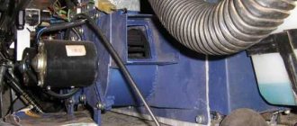
UAZ is a legendary SUV, popular both in Russia and beyond its borders. The car has been produced for quite a long time, which has proven the reliability of its design. This machine is actively used in the army. There are minor differences between the civilian and military versions. However, both here and there the UAZ front axle showed its best side. There are several modifications: on-board, regular, “loaf”, etc. Also, one cannot fail to note one of the advantages of the car - maintainability and the ability to restore the functionality of any unit, even in “garage” conditions. The mechanism allows you to activate all-wheel drive, which helps you confidently overcome obstacles.
Front and rear axles are almost identical
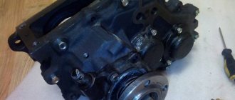
UAZ front axle structure
It consists of a crankcase (sometimes called a stocking), a differential and a final drive. The rear and front axles have no fundamental differences. The only difference is in the direction of the thread of the oil rejection ring located in the main gear. The current design of the UAZ front axle is shown in the picture below. The support placed on the casing is fixed with five hardware. Pin bushings are pressed into the support. A pair of pins “engages” in holding the fist. He also holds the housing cover of the wheel gearboxes. A pin is fixed on it along with a shield on which there are parts of the brake system.
The pins do not rotate in the fist thanks to pin-type stoppers. The fist itself is made with preload (0.02-0.1 mm). The UAZ 469 axle is adjusted using spacers. Location: between the turn lever and the trim (left or right). The spacers are located between the pads and the fist.
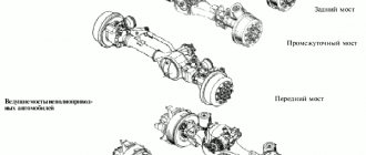
Bridge diagram
One of the features of the described mechanism is that, in addition to increasing cross-country ability, it also turns the wheels. For this purpose, Birnfield ball joints are used. Their cavities contain lubricant that does not need to be replenished throughout their entire service life. The cams, as well as the axis of the pins, are inclined, which allows the wheels to be returned to the middle position after making a turn. The main advantages of the beam (Spicer):
- track is 1.6 m, which has a positive effect on the stability of the car;
- the wheels rotate at an angle of up to 32 degrees, which gives the machine improved maneuverability;
- instead of leaf springs, a dependent suspension on springs is mounted;
- no need to replace lubricant in mechanisms (fists);
- removable cover facilitates access to parts in case of repair;
- the differential together with the gearbox are in one housing - this increases rigidity and service life;
- An improved satellite gear has reduced noise.
Particularly worth mentioning are the hinges, or more precisely the stabilization of angular velocity. This is a design that ensures the stability of rotation of two shafts: the drive and the accompanying. The hinge includes two forks: in their sockets there are 4 balls. In the middle sectors of the parts there is a fifth one, needed for installation operations. In particular, centering the fork. To deactivate the front-wheel drive, there is a special device consisting of a clutch, bolts, and balls.
Distinctive features of the military version
The main feature of the front axle in the military version is the placement of the gearbox. It is located higher. The second distinctive point is the gear ratio - 5.38. The civilian version of UAZ 469, 452, 3151, 3303 has 4.6 or 5.125. All these characteristics increase the distance from the bottom of the car to the road surface from 220 to 300 mm. Those who want to quickly replace an ordinary bridge with a military one will be disappointed: this will not work without alterations. The reason is in the design of the bipod and suspension. In addition, driveshafts differ in length.
A real “cart”!
Malfunctions and repair work
Common malfunctions of the UAZ front axle and possible repairs:
- Leakage of lubricating fluids. Check the tubes and connecting elements for mechanical damage - the cuffs and flange for functionality, the oil container for the optimal fluid level.
- High wear of fasteners.
- Bearing defects caused by the use of poor quality material by the car plant.
- Broken axle teeth. Adjustment will not help; parts need to be replaced.
- Mechanical defects of the beam.
- Wear of elements. The situation is resolved by replacing it with new spare parts.
- Poor grip of the bearings and main gears indicates the need for tension adjustment.
Bridge repairs begin after diagnosing and searching for the cause of problems in the functioning of the mechanism, which are diverse:
- transmission components of a rear-wheel drive vehicle are faulty due to regular movement over difficult terrain;
- use of consumables and lubricants of unsuitable quality;
- Failure to monitor tire pressure can lead to shaft and bearing failures.
Most often, car owners are faced with a violation of the axial space of the kingpins and are knocked out of the required position. To diagnose, you need to jack up the front of the vehicle and move the wheel in a vertical plane. The presence of axial play indicates the need to adjust the clearance of the pins.
How to adjust bridges
You can adjust the UAZ axles yourself. This will require a number of tools and good knowledge of the mechanism. Access to the necessary parts and assemblies is possible after dismantling the structure and separating the crankcase parts. The first sign of the need to adjust the gearbox is loud noise and malfunctions of the part. Such work is required after diagnosing the condition of bridges. Adjustment includes a number of activities.
At the first stages of repair work, ensure that the nuts of the brake elements can be loosened freely. The tools you will need are a split wrench, brake fluid and a mixture of WD-40. The bridge is dismantled as follows:
- remove the fasteners between the drive gear flange and the propeller shaft;
- secure the shaft to the side;
- place the front part of the vehicle on jacks, raising the wheels above the surface;
- additionally install safety supports;
- remove the nut between the brake pipe and hose and close the hole with a plug to avoid large losses of fluid;
- after removing the lower fasteners and moving the shock absorbers from the axle, the bridge will lower;
- remove the stepladder nuts and roll out the bridge (without wheels it weighs more than 100 kg).
For adjustment and repair work, you will again need a split wrench, a metal corner with pins, a universal puller, a container with brake fluid, transmission oil (if you don’t want to fill in the old one), a set of bearing spacers for adjusting the driven gear and a micrometer. Preparatory work:
- remove 10 bolts connecting the axle shafts to the hubs;
- remove the axle shaft from the crankcase;
- Unscrew the fasteners of the brake pipes;
- remove the tee from the bracket;
- remove the connecting elements between the crankcase parts, keeping the gasket;
- Remove the differential housing and driven gear, outer rings.
The main support of the drive gear, which determines the reliability of the bridge, is a tapered roller bearing located in the front part, consisting of 2 rows. A similar part on the opposite side performs an auxiliary function. To repair, you will need to remove the right drive gear by removing the bolts.
All disassembled components should be inspected for wear and replaced if necessary. The shims are located in the middle of the inner rings of the bearing. Their thickness is measured with a micrometer, the part with the smallest value is removed to create preload in the bearing. Adjust the part until the dynamometer shows a resistance of no more than 3.5 kgf. Otherwise, you will need to remove another gasket. Tight turning indicates the need to increase the thickness of the gasket pack. After determining the desired value, you can put the unit back together.
The next step is to adjust the differential bearings:
- press in the outer and inner rings;
- mount the differential with the main gear into the crankcase;
- install the gasket;
- separate the crankcase parts;
- remove the differential, check the clearance of the differential and bearing rings;
- install the main gear mechanism on the right side of the crankcase;
- install the drive shaft;
- pull together the crankcase halves, observing the required gap size, adjusting it if necessary with cardboard spacers.
After all the work, it is necessary to assemble the bridge back and install it on the car. At the same time, you can lubricate the parts and replace worn fasteners.
How to remove the shank
It is possible to repair, replace and adjust the shank only after removing it. To do this, it is necessary to check the backlash at the beginning of work. Then you will need to perform the following operations:
- Turn the cardan clockwise until it stops. At this point, make a mark on the body of the structure.
- Turn the cardan in the opposite direction until it stops. Make a second mark.
- Control between the designated positions of the maximum permissible distance is 11 mm.
- Removing the cardan flange, tightening the nuts.
- Checking the backlash. Removing the front axle.
- Removing the nut and shank.
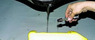
- Removing oily liquid.
After this, the wheels and steering controls can be removed.
How to shorten a bridge
Before shortening the axles, it is necessary to remove the axle shafts. You will need to perform the following manipulations:
- cut the stocking;
- select a pipe of suitable diameter and install it inside;
- welding work;
- cut off the axle shaft;
- cut a hole on a lathe and mount the axle shaft into it;
- Weld the resulting structure on both sides, remove excess parts.
In this way you can make a bridge for 80 cm gauge.
Replacing the bearing and shank oil seal
Replacing the front axle shank bearing and oil seal includes the following activities:
- Dismantling old parts (bearings and oil seal).
- Replacing a worn bushing to prevent damage to new components.
- Installation of new parts, flange and fasteners.
The tightening of the nuts during operation must be controlled with a dynamometer to create the necessary resistance. For new bearings, the preload is greater than for used parts. Upon completion of the work, it is necessary to install the axle shafts and cardan, add oil.
How to rebuild the rear axle
For repair work and replacement of worn parts, you will need to go through the structure. Sequencing:
- Disassembling the UAZ rear axle begins with removing the fastening elements of the washer, shank and flange.
- Removing the bearing cover.
- Disconnecting the additional gear, removing the differential.
- Working with the satellite box: all components must be removed and inspected for wear.
- We remove the rear axle.
- When everything is disassembled, diagnose the components for mechanical damage and the need for lubrication.
- Replacement of old parts with new elements.
The assembly of the structure occurs in the reverse order.
How to turn on the front axle on a UAZ
To transfer torque to the gearbox, a cardan shaft is used, connected to a transfer gearbox that has a pair of stages. Patriot cars use two types of transfer cases: Russian mechanical or Dynamos, which has an electric drive. The latter option has been in use since 2013. In both options, you cannot do without a clutch for engaging the front axle of the UAZ.
The drive is controlled using a lever or washer located on the central tunnel. To turn on or deactivate the UAZ front axle, you need to:
- Fully depress the clutch;
- Move the lever to the desired position (the modes are indicated on the plastic handle). Carry out the operation at a speed of no more than 60 km/h;
- Release the clutch: you can then drive with the axle activated. To disengage it, depress the clutch again and move the control lever to neutral.
Engaging the axle on SUVs with a Dymos gearbox is much simpler: you need to turn the washer to the desired position. The design of the transmission is such that it is not forbidden to connect the axle directly while driving. However, if a reduced speed is required, you will have to stop.
Lever options
UAZ 469, 452, 3303 we repair the front wheel drive CV joint.
UAZ-469, 452, 3303
The main advantage of UAZs is all-wheel drive. For this, the owner is ready to forgive the car many shortcomings - high cross-country ability and simplicity of design make them tolerable.
But over time, when driving with the front end turned on, an ominous crunch appears, and the wheels slightly “bite” when cornering. The reason is most likely the wear of the CV joints. And it develops if there is longitudinal play in the hinge due to wear of the thrust rings. At the next TO-2, it is worth checking their condition. For this:
| Using a 14mm wrench, unscrew the six coupling nuts. | . and remove it. |
| Holding the splines of the drive, we move it towards and away from us. If you notice any play, the steering knuckle will have to be disassembled to replace the thrust washers of the hinge. | Unbend the lock washer. |
| ...and unscrew the nut. | Remove the lock washer. |
| Unscrew the second nut and remove the bearing thrust ring. | Remove the outer bearing and hub. |
| Using a 17mm wrench, unscrew the six bolts securing the brake shield and axle. | We remove the boot... |
| ...and the brake assembly. And so as not to interfere, we put it on a spring. | We remove the trunnion. |
| We take out the drive and wash the parts in kerosene. |
Sometimes the hinge falls apart right in your hands. In order to make such a CV joint continue to work, it is necessary to eliminate the axial play and align the rotation axes of the hinge and the steering knuckle. When installing a new hinge, these conditions must also be observed, otherwise it will quickly fail.
| If the axle support washer is worn. | . we knock the puck out. |
| . remove the second support washer from the ball joint. |
We find the thickness C of the support washers using the formula: C = (B-A)/2, and their diameters correspond to the diameters of the sockets.
| Using a caliper, measure the distance A between the hinge support cheeks. We measure the distance B from the socket of the support washer to the end of the ball joint. |
Washers to compensate for play can be machined from steel (steel 45) and hardened. We press them into the axle and ball joint.
| Before assembly, fill the hinge cavity with AM or CV joint grease (about 500 g per hinge). |
We carry out assembly in reverse order. Having installed the axle and brake shield, we check whether there is any longitudinal play at the hinge and whether it rotates freely. Do not over-compress the joint. In this case, you need to remove the support washers and reduce their thickness.
Maintenance
Maintenance of the UAZ bridge is simple and comes down to monitoring the level of lubricant and topping it up and replacing it. The second point is to check the seals for leaks. It is regularly necessary to check the reliability of the fastenings, especially if the machine is used in difficult road conditions. Eliminate axial play in the differential bearings in a timely manner.
Assembly and connection diagram
When assembling the structure, do not remember several features:
- Press the bushing into the trunnion flush with the end of the washer socket. After completing the procedure, the sleeve must be deployed;
- Place one thrust washer inside the trunnion, the second - in the support. The oil lines in the thrust washers should face the joint. The washer is secured by punching in 3-4 places;
- When installing the hinge, add lubricant to the ball joint;
- Treat the pins and bushings with liquid lubricant.
To obtain the required axial tension, you need to select a certain number of spacers (but not less than five). They are installed on the ends of the knuckle body at the top and bottom. Their number should be the same. Soak the felt ring of the ball joint oil seal with engine oil. If possible, check the bridge on a bench after assembly. If the assembly is done correctly, the axle shafts should not heat up or make excessive noise when braking. Leaks through seals, cuffs, and bolted connections are not allowed.
How to disassemble a bridge
The first step is to remove the brake drum. Next, the hubs and hubs are dismantled. Along the way, inspect the bearings, which may have worn out and will have to buy new ones.
Further:
- Unscrew the brake system hose, it will get in the way, and remove the brake shield;
- Pull out the CV joint;
- Remove the rotating mechanism and shank;
- Divide the stocking into two parts;
- Remove the pair from one part of the bridge and the other.
Dismantling the bridge when the car is in a hanging position
Adjusting the bearings of the final drive of the UAZ Patriot
Axial play in the bearings of the main gear drive gear is not allowed, since if it is present, rapid wear of the gear teeth occurs and the axle may jam.
Check for the presence of axial clearance by rocking the drive gear by the driveshaft mounting flange.
To eliminate the axial play of the drive gear, it is necessary to tighten nut 8 (Figure 1).
At the same time, keep in mind that the nut is cored into the groove of the threaded part of the drive gear and when tightening it will require more force on the wrench.
Tighten the nut carefully until the axial play of the drive gear is eliminated, avoiding overtightening, then tighten the nut.
If it is not possible to tighten the cored nut, then it should first be loosened by 0.5 - 1.0 turns, and then tightened until the axial gap is eliminated and cored.
Axial play in the final drive differential bearings is also not allowed.
Check it by rocking driven gear 2 with crankcase cover 21 removed.
Eliminate the axial play of the driven gear of the main gear by tightening the nut 17 of the differential bearing, having first removed the locking plate 19.
Adjust the main drive bearings in the following order.
1. Select adjusting ring 5 (see Fig. 1). Its thickness d1 (Fig. 2) is determined (with an accuracy of ±0.025 mm) based on the actual dimensions B and D (see Fig. 2 and 3) using the formula d1 = B – (111.960 + G) (mm).
Install the ring into housing 16 (see Fig. 1) of the main gear.
2. Install the drive gear shaft into the front axle housing.
Check the torque of the drive gear shaft. It should be 1.0–2.0 N cm (0.1–0.2 kgf cm).
3. When installing the differential assembly with the driven gear, measure dimension E (Fig. 4), applying an axial force P equal to 4000–5000 N (400–500 kgf), and turning the gear several times so that the bearing rollers take the correct position.
Measure distance B in the crankcase (see Fig. 2) from the axis of the drive gear to the thrust end of the differential bearing.
Based on the actual dimensions B, E and the mounting size of the driven gear, equal to 50 mm, select (with an accuracy of ±0.025 mm) the adjusting ring according to the formula d2 = B – (E + 50 + X) (mm), where d2 is the thickness of the adjusting ring; X - maximum deviation from the mounting dimension, equal to 50 mm, with the corresponding sign (plus or minus), this dimension is applied with an electrograph to the end of the driven gear.
4. Install the differential assembly with the outer rings of its bearings and the adjusting ring into the front axle housing and secure it.
5. Adjust bearings 6 and 22 (see Fig. 1) of the front axle differential by tightening nut 23, periodically rotating the differential so that the bearing rollers take the correct position. After tightening the nut, the total turning torque of the differential drive gear (Mv.w.) must be within Mw. w. + (0.21–0.42) (Nm) . Perform the check by turning the drive gear.
Check and adjust the lateral clearance in the meshing of the gears of the installed new final drive kit after adjusting the position of the gears.
The lateral clearance is checked with an indicator, the stand of which is attached to the axle housing in the direction perpendicular to the surface of the driven gear tooth when the indicator stand is attached to the housing.
Check the gap on three or four teeth evenly spaced around the circumference.
The spread of the gap values should not exceed 0.05 mm.
Normal side clearance should be between 0.15–0.25 mm.
If the side clearance is less than the specified value, then the selected adjusting ring should be replaced with a ring of thinner thickness.
When checking and adjusting the side clearance, it is not necessary to preload the differential bearings.
6. Tighten the adjusting nut 23 until it comes into contact with the bearings and there is no gap in them.
7. Check the engagement of the main gears along the contact patch by painting the teeth of the driven gear with paint (2 teeth in three or four places evenly around the circumference).
8. Braking the drive gear shaft by the flange, rotate the driven gear in both directions until contact marks appear on the gear teeth, as shown in Fig. 5
When adjusting the gear mesh correctly, the contact patch should be located in the places of the teeth shown in the figure (item 1)
When there is contact at the top of the tooth (item 2), move the drive gear towards the driven gear, increasing the thickness of the adjusting ring, and to maintain the value of the side clearance, move the driven gear away from the drive gear.
If there is contact at the base of the tooth (item 3), move the drive gear away from the driven gear by reducing the thickness of the adjusting ring, and to maintain the side clearance value, move the driven gear towards the drive gear.
If there is contact at the narrow end of the tooth (item 4), move the driven gear away from the drive gear by reducing the thickness of the adjusting ring, while moving the drive gear towards the driven gear to maintain the side clearance value.
If there is contact at the wide end of the tooth (item 5), move the driven gear towards the drive gear by increasing the thickness of the adjusting ring, and to maintain the side clearance value, move the drive gear away from the driven gear.
Install the locking plate onto the differential bearing cap.
After assembling the final drive, check its heating after a test drive of the car.
If the front axle housing in the area of the pinion bearings and differential bearings heats up above 90°C, then adjust the bearing preload again as indicated above.
Repair of the most common faults
Restoring the bridge to operability is not very difficult: but it is required to be careful when performing operations. What “diseases” are most common?
Leak formation
Where the steering knuckle connects to the bridge, there is an oil seal - one of the weak points of the design in terms of lubricant leakage. The oil seal can leak oil not only due to wear, but also when the breather is clogged. If you add more lubricant than required, the result will be the same: a leak. There are two types of oil seals:
- rubber: inexpensive, but also short-lived;
- polyurethane: more expensive, have a long service life.
To replace a part, place the car on a level place and jack up the problem side, loosening the wheel nuts in advance. Further:
- remove the steering knuckle;
- clamp the part in a vice;
- pull out the oil seal by prying it with a flat screwdriver or other suitable tool;
- pull the oil seal out of the support cavity;
- Lubricate the seal before installation;
- press in the oil seal using a tube of the appropriate diameter.
- Installation is in the reverse order.
The most problematic place of the bridge
The mechanism began to hum
First of all, check the oil level. If it is normal, the bridge will have to be removed and disassembled. If the bridge hums constantly in any driving mode, the reasons may be as follows:
- incorrect setting or limiting service life of differential bearings;
- breakage (wear) of the axle shaft (its bearing);
- wear, damage, incorrect gear adjustment.
These bearings simply need to be replaced with new ones. If a humming noise appears during a sudden stop or acceleration, the reasons are as follows:
- incorrect clearance between the final drive gears;
- The final drive gear teeth do not mesh correctly.
In this case, you need to correctly adjust the gearing or replace defective parts. If the bridge hums when the UAZ enters a turn and moves in a straight line, the reasons may be the following:
- satellites rotate with great effort;
- abnormal operation of the axle gears in the differential;
- destruction, severe wear of the axle bearing;
- incorrect clearance between gears located in the differential.
To restore the functionality of the mechanism, adjust the clearances correctly and replace damaged, worn bearings. It is worth noting that the desired result when adjusting the gaps can only be achieved on a bench.
Wheel axial play
It occurs when the wheel bearings are incorrectly adjusted or when they completely fail, which is caused by over-tightening. As a result, the bearings become very hot, the smear liquefies and flows out. Algorithm of actions when performing the correct adjustment:
- Jack up the wheel on the desired side;
- Use a puller to remove the axle shaft;
- Move the lock washer to the side and unscrew the lock nut;
- Spin the wheel: if it rotates tightly, the reason may lie in jamming of the cuffs, contact of the drum and pads, etc.;
- Tighten the adjusting nut. Do this gradually while spinning the wheel. Use the WRENCH;
- Unscrew the nut about a third of a turn and install the lock washer. Tighten the nut and lock it;
- Check how the wheel rotates: it should spin freely without sticking;
- Replace the axle shaft, replace the bolts and tighten them.
You can finally check while moving. If the hub gets very hot, loosen the hub nut about 1/6 of a turn.
Removing the axle shaft
UAZ pivot unit
The usual design of the kingpin on an UAZ is famous for its problems: you constantly need to check the play connecting the steering knuckle to the ball joint, monitor the presence of lubricant, notice problems with the gaskets in time and eliminate them. We offer modernized kingpins with bronze liners and bearings. The kingpin with bronze inserts is very durable; it will not be damaged even if the suspension is hit hard. They performed well both on and off the road. The kingpin on bearings is also very practical to use. Driving the UAZ becomes much easier.
Steering knuckle boot N/A UAZ with Timken, Spicer, Hybrid axles (2 pcs. set)
Steering knuckle boot N/A UAZ with Timken, Spicer, Hybrid axles (2 pcs. set)
The boot serves to hermetically protect the hinge of the support steering knuckle of the front axle of the UAZ vehicle. Applicable to all bridge models: Timken, Spicer, Hybrid (except Military Bridge). The boot is installed to replace the existing sliding cuff. Installs without disassembling or removing the unit.
1) complete sealed protection of the SHPOK from water and dirt;
2) installation without disassembling and removing the fist;
3) the unit becomes maintenance-free (no need to syringe);
4) ensures tightness even with backlash in the pins and corrosion of the ball surface;
5) the design is made in such a way that even if the corrugation breaks, it works as a standard seal;
6) Applicable to all bridges (Timken, Spicer, Military).
1) Thick rubber boot (thickness 4.5 mm)
2) Fastenings (bracket - 4 pcs., lock - 2 pcs., clamp - 2 pcs.)
3) Hexagon fastening bolts - 8 pcs.
The material of the boot, the rubber from which the boot of the CV joint of a vase is made, is only thicker. It is possible to supply a boot made of polyurethane.
Important! The use of boots on bridges with a working angle exceeding the established one is unacceptable.
When developing the boot, the operating range of rotation established by the manufacturer was taken into account. Exceeding this value leads to the fact that there is no gap left on the folding side and strong compression of the boot folds by the metal parts of the ShOPK occurs and subsequent rupture of the boot. Therefore, the use of boots on bridges with a working angle exceeding the established one is unacceptable.
- UAZ pivot unit
Steering knuckle boot for UAZ gearboxes (military) (2 pcs. set)
The boot serves to hermetically protect the hinge of the support steering knuckle of the front axle of the UAZ vehicle. Application: Installed on UAZ vehicles with gear (military) axles, Bars axles, on all-terrain vehicles "TREKOL", Niva Marsh and analogues.
The boot is installed to replace the existing sliding cuff. Installs without disassembling or removing the unit. Differences from boots on “civil bridges” • Increased diameter of the neck (65 mm) • Increased length of the clamp Advantages: • complete sealed protection of the SHPOK from water and dirt; • installation without disassembling and removing the fist; • the unit becomes maintenance-free (no need to syringe); • ensures tightness even with backlash in the pins and corrosion of the ball surface; • the design is made in such a way that even if the corrugation breaks, it works as a standard seal;
Delivery set: 1. Thick rubber boot (thickness 4.5 mm) 2. Fastenings (bracket - 4 pcs, lock - 2 pcs, clamp - 2 pcs) 3. Hexagon fastening bolts - 8 pcs 4. Washer - 16 pcs 5. Nut — 8 pcs Important! The use of boots on bridges with a working angle exceeding the established one is unacceptable. When developing the boot, the working rotation range established by the manufacturer was taken into account (the manufacturer laid down these restrictions since exceeding the rotation angle beyond the norm leads to a sharp increase in loads on the CV joint, its rapid wear or even destruction). Exceeding this value leads to the fact that there is no gap left on the folding side and strong compression of the boot folds by the metal parts of the ShOPK occurs and subsequent rupture of the boot. Therefore, the use of boots on bridges with a working angle exceeding the established one is unacceptable. And failure of the boot in these cases will not be considered a warranty. This type of defect is easily determined by the characteristic imprint and shape of the gap.
- UAZ pivot unit
Disassembling the steering knuckle without dismantling the bridge
To perform this operation, first disconnect the hub by unscrewing the 6 bolts. Then bend back the lock washer, unscrew the hub nuts and remove it with the wheel and drum. Further:
- disconnect the oil deflector by unscrewing 6 bolts;
- remove a couple of bolts on the steering knuckle, hang the brake shield on the spring;
- remove 6 bolts to disconnect the cover and the knuckle body;
- to remove it, unscrew the bolts and remove the o-rings;
- Unscrew the knuckle linings, remove the kingpins and remove the steering knuckle housing.
As you can see, it is quite possible to repair the front axle of a UAZ with your own hands. However, you need to have experience in carrying out such work and a good set of tools.
If you have any questions, leave them in the comments below the article. We or our visitors will be happy to answer them
Design Features
The axle housing consists of a one-piece cast main gear housing, axle shaft housings (stockings) pressed into it, and a stamped housing cover.
The absence of a connector in the transverse plane of the bridge gives the structure high rigidity, the unloaded connection between the cover and the crankcase reduces the likelihood of leakage at the joint, and the placement of the main gear and differential in a single crankcase ensures high precision of engagement and more favorable conditions for the operation of bearings.
Thanks to all these design features, the actual service life of bridges has increased significantly. In addition, now to access the main gear and differential there is no need to remove it and “halve it” - you just need to remove the cover.
To reduce warping of the driven gear during its heat treatment and, as a result, reduce noise, increase the reliability and durability of the main gear, the thickness of the “substrate” of the driven gear was increased by 8 mm. However, this measure led to a change in the left differential cup. But, the new differential can be used on previous single-stage axles with a split crankcase, provided that a compensator ring is installed on the cup stud.
Spicer bridges are unified with single-stage bridges of the old design in a number of other details. These are differential bearings, rear axle axle shafts and almost all parts of hub units. The front bearing with a double seal (469-2307086-03) and the new double-edge seal of the drive gear flange are unified with similar parts of U-shaped (“military”) axles produced by UAZ OJSC.
As for the front drive and steering axles, here, in addition to the above points, it should be noted the new constant velocity joints ( CV joints ) of the " Birfield " type, which are much more durable than the hinges of the old design (" Weis "). Currently, all bridges of the Spicer and Timken types are equipped with such hinges. It would be worth recalling that to lubricate the Birfield hinges, a special CV joint grease is used, which must be placed not into the entire internal cavity of the steering knuckle, as before, but only into the hinge itself. The use of other types of lubricants, including the traditional Litol-24, is unacceptable. During operation, adding lubricant to the joint is not required. The internal cavity of the steering knuckle is still filled with Litol-24 lubricant.
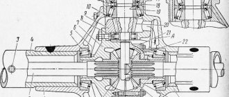
Main gear: 1 – bolt; 2, 33 – spring washers; 3 – driven gear; 4, 24 – axle shafts; 5 – adjusting ring; 6, 22 – bearings; 7 – spacer sleeve; 8 – outer race of the outer roller bearing; 9 – roller bearing; 10 – thrust ring; 11 – oil seal; 12 – reflector; 13- flange; 14 – washer; 15 – nut; 16 – axle housing; 17 – adjusting ring of the drive gear; 18 – outer race of the internal roller bearing; 19 – internal roller bearing; 20 – oil deflector ring; 21 – shaft with drive gear; 23 – adjusting nut of differential bearings; 25, 39 – right and left parts of the differential housing; 26 – bolt; 27, 40 - support washers for axle gears; 28, 43 – axle gears; 29, 45 – differential satellite axes; 30, 41, 44, 46 – differential satellites; 31, 38 – differential bearing covers; 32 – retainer for the differential bearing adjusting nut; 34, 36, 37 – bolts; 35 – main gear housing cover; 42 – final drive housing cover gasket
The ones produced have a gear ratio of 4.111 (37:9) or 4.625 (37:8). Axles with a gear ratio of 4.111 are installed mainly on cars with gasoline engines, and with a gear ratio of 4.625 - on cars with diesel engines.
How to protect your fist from wear
If the loaf was purchased recently, then the car owner may hear unpleasant sounds of metal rubbing against metal without lubrication when turning the steering wheel. The fists on the UAZ can be protected with lithol.
If you have no experience in auto repair, the fists can be coated with lithol only on the outside. Drivers more advanced in repairs can unscrew the circular oil seal, move it to the middle of the car and pour lithol into the resulting gap.
You should never forget about the need to carry out preventive inspections of the steering knuckle clamping bushings, replace the lubricant in the steering knuckle and identify play in the suspension.
If the steering knuckle needs repair, you can do it yourself or by contacting an auto repair shop.
It's hard to imagine a car that doesn't have a steering knuckle. This part is necessarily present on the UAZ Patriot SUV and performs a very important function. Why is a steering knuckle needed on a UAZ Patriot SUV, how is it replaced and what do you need to know? You can find out about this in this material, which is dedicated to the steering knuckle of the UAZ Patriot SUV.
Replacing king pins
There are also parts that need replacing from time to time - these are the king pins. To replace them, you will have to remove the steering knuckle and hold it in a vice. After this, using a mandrel, you should knock out the pin bushings and thoroughly clean the passages for lubrication and for the replacement spare part in the knuckle.
After using a mandrel, new bushings are installed so that the holes in them coincide with the holes on the knuckle, and the open ends point towards the beam mounted on the front axle.
Simultaneously unroll both bushings to the required diameter. After this, the bushings are cleaned and a thin layer of lubricant is applied. Then, having lubricated the sealing rings and ducts in the knuckle bosses, install the rings themselves.
Wheel and brake removal process
To remove the wheel, you must perform the operations in this sequence.
- Remove the cap from the wheel hub, remove the R-shaped bracket, and dismantle the locking head. Loosen the nut on the drive shaft that connects it to the hub. After that I remove the front wheel.
- If the car model is equipped with an ABS system, there is a sensor on the wheel that must be removed.
- The nut securing the drive shaft to the front suspension hub is twisted.
- The brake caliper is attached to the steering knuckle with two bolts, which must be unscrewed and disconnected from the brake disc, after which it is tied to the spring on the front suspension.
- Before proceeding with the removal of the brake disc, it is necessary to note its location relative to the suspension hub. The line can be applied with chalk, but it is better to use white paint so that the line is not erased during repair work. Only after this, unscrew the fastening screw and remove the brake disc.
Approximate cost on the market
It could also be a left or right steering knuckle. Outwardly, they are almost identical, but since these details are directly related to each other, it is best to play it safe. On one of them there is a bipod; on the other there is no access to the longitudinal thrust. It is for these reasons that their prices differ.
Auto parts can be purchased at auto stores, car markets, and ordered on various websites. The right steering knuckle costs approximately 8,400 rubles, the price for the left one starts at 6,530 rubles. These are approximate prices for the UAZ-31519.
You should not save, even if the cost of domestic spare parts is higher than Chinese ones. More than likely, an expensive part will last much longer.
Features of prevention and repair
Repair of the UAZ steering knuckle can be carried out either independently or by contacting a car repair shop. The cost of repair work will depend primarily on the price of the parts to be replaced.
If you have some experience and the necessary set of tools, having studied the instructions on how to disassemble and repair the steering knuckle, it is enough to buy the required spare parts and carry out all the repairs yourself. This will not only save money, but also gain new knowledge about the design of the car.
We must not forget about regular preventive measures, which consist of inspecting and assessing the condition of the steering knuckle clamping bushings, as well as identifying the presence of play in the front suspension.
Before you begin repairing the steering knuckle, you need to familiarize yourself with the features of its implementation.
- If Nyloc nuts are installed, they will definitely need to be replaced, as they have a special coating that prevents them from unscrewing and loosening the clamp. After screwing the nuts, this coating is destroyed.
- You cannot put the car on wheels if at least one drive shaft is disconnected from the hub, as this can lead to deformation or destruction of the hub bearing. If it is necessary to move the machine a short distance, the shaft must be returned to the hub and secured with a nut.
- Depending on the model of the car and the year of its manufacture, the UAZ knuckle has two modifications, in one of which the hubs are solid, and in the other they are hollow, which is determined by the presence of a hole.
Before starting repairs, the following manipulations are carried out.
- The car is put on the handbrake.
- Stops are placed under the rear wheels to prevent the car from moving.
- The front part of the car is raised with a jack or winch and fixed on supports.
Only after making sure that the front part of the car is securely fastened and that it cannot move or fall off the stops can you begin to remove the wheel.
Purpose of the mechanism
Everyone knows that wheels turn thanks to steering. Under the influence of the steering rack, the angle of the front wheels is changed. Changing the angle is ensured by the presence of a rotating element, which allows the wheel to turn to the right or left.
Thus, we can say that the steering knuckle is designed to be able to change the angle of the front wheels. That is, in simple terms, if this device did not exist, the car could only move straight without the ability to turn.
But besides this, this device also performs the following functions:
- Possibility of connecting the wheel via a hub with suspension elements.
- Attaching the wheel hub to the product.
Connection diagram
Shaft 11 rotates in a roller bearing, which is installed in the wheel gear housing cover, and a bronze bushing located inside the axle 18. At the end of shaft 11 there is a mechanism that disables the front wheels of the machine. The device consists of movable couplings 14 and 15. They are located on the splines of the shaft and bolt 17 and 16 with a spring and a ball.
These movable couplings, with their external splines, are connected to the internal splines of the drive flanges 13 and 14, which are bolted to the wheel hubs. In order to reduce wear on the metal surfaces of the parts of the front axle of the UAZ 469, as well as to save fuel when driving on paved roads, it is recommended to also turn off the front wheel hubs while disabling the front drive axle.
To carry out such a shutdown, it is necessary to remove the protective caps 16 and 18. Next, unscrew the bolts 16 and 17 from the shaft hole 11. Place the coupling in such a position that the signal ring groove “a” on its plane is in the same plane as the end of the flange. When the coupling is installed in the required position, the protective caps must be tightened.
By screwing in bolts 16 and 17, you need to turn on the wheels. The bolts should be tightened securely. Disabling and engaging must be carried out on two wheels of the front drive axle simultaneously. It is not allowed to engage the front axle with the wheels off!