Engine tightening torques d 260
Checking the tightening of the bolts securing the cylinder heads
of the D-260.1 diesel engine
Checking the tightness of the cylinder head bolts must be done at the end of the run-in and after 1000 hours of operation on a warm diesel engine in the following sequence:
• remove the caps and cylinder head covers;
• remove the rocker arm axles with rocker arms and struts;
• use a torque wrench to tighten all cylinder head bolts, having previously loosened them by 1/6 of a turn, to a torque of 200 ± 10 Nm in the sequence shown in Figure 13.
After checking the tightness of the cylinder head bolts, replace the rocker arm axles and adjust the gap between the rocker arms and valves in accordance with the instructions in section 3.3.10. Reinstall the cylinder head covers and caps.
3.3.10 Checking the gap between valves and rocker arms
diesel engine D-260.1
Check and adjust the gaps after 500 hours of operation after checking the tightness of the cylinder head bolts or, if necessary, on a cold diesel engine (water and oil temperature should not exceed 60 °C).
The gap between the ends of the valve stems and the rocker arms should be
0.25 mm for intake and 0.45 mm exhaust valves.
When adjusting the gap between the end of the valve stem and the rocker arm on a cold diesel engine, set:
Make adjustments in the following sequence:
• remove the cylinder head caps and check the tightness of the bolts and nuts securing the rocker arm axle stands;
• turn the crankshaft until the valves in the first cylinder overlap (the inlet valve of the first cylinder begins to open, and the exhaust valve finishes closing);
• adjust the clearances in the third, fifth, seventh, tenth, eleventh and twelfth valves (counting from the fan), then rotate the crankshaft one revolution, setting the overlap in the sixth cylinder, and adjust the clearances in the first, second, fourth, sixth, eighth and ninth valves.
To adjust the gap, loosen, in accordance with Figure 14, the lock nut 2 of the adjusting screw 3 and, screwing the screw in or out, set the required gap between the rocker arm striker and the end of the valve stem according to feeler gauge 1.
After setting the gap, tighten the lock nut and check the gap again with a feeler gauge while rotating the rod. After adjusting the valve clearance, replace the cylinder head caps.
The valves can also be adjusted on each cylinder when the piston is at top dead center.
To do this, rotate the crankshaft until the piston of the first cylinder is installed at top dead center, corresponding to the end of the compression stroke (the dowel pin indicator on the timing gear cover and the TDC mark on the torsional vibration damper housing scale are aligned) and adjust the clearance in the valves of the first cylinder.
Turn the crankshaft 1/3 of a turn and adjust the valve clearance of the fifth cylinder, i.e. Adjust the valve clearance in the sequence corresponding to the operating order of the cylinders (1-5-3-6-2-4), turning the crankshaft 1/3 of a turn clockwise.
Source
Installation of valve overlap of the first cylinder
It's written in the instruction manual. What is necessary is to bring the piston of the first cylinder to top dead center when the valves close. This causes confusion about what needs to be done.
In fact, everything is very simple.
Installing the piston at TDC
When the piston of the first cylinder is brought to top dead center. There are two possible valve behavior options. During one work cycle, the crankshaft makes two revolutions. Accordingly, the piston approaches TDC twice. The compression stroke occurs once. Both valves are completely closed. Since it is necessary to create compression in the combustion chamber. The second time is the exhaust stroke. The exhaust valve closes at TDC after passing TDC the intake valve opens. For air intake in case of a diesel engine and fuel mixture in case of a gasoline engine.
To adjust the valves on the D260 engine, it is proposed to set the piston of the first cylinder to TDC when the compression stroke ends and the air intake begins.
In practice it will look like this. Rotate the crankshaft until the exhaust valve begins to close. The valve is closed, turn it a little more and the exhaust valve opens. Then move the crankshaft back so that both valves are closed. You can check yourself on the sixth cylinder. The piston in it will also approach the top dead center. At the moment when the piston moves upward, both valves are closed and stationary.
The compression stroke will occur in the sixth cylinder. And at this moment the valves on the sixth cylinder can be adjusted.
There is no need to remove the injectors when adjusting the valves. But it is required to bring the pistons of the first and sixth cylinders as accurately as possible to TDC.
Installation according to the mark on the pulley
To do this, there is a TDC mark on the pulley; it must be aligned with the alignment pin.
The procedure for adjusting valves on the D 260 engine
The pistons of the first and sixth cylinders are at TDC. The exhaust stroke has ended on the first cylinder. On the sixth compression stroke.
Valve numbering starts from the cooling radiator
In this position, valve clearances 3, 5, 7, 10, 11 and 12 are adjusted if counted from the radiator.
Then you need to turn the crankshaft one revolution to set the mark on the pulley to the TDC position
In this position, valves 1, 2, 4, 6, 8 and 9 are adjusted according to the radiator
Please note that the piston of the first cylinder is now at TDC on the compression stroke.
This is the easiest and most convenient way to adjust. If it is not clear and raises doubts. You can use another method. But it will be much more difficult to implement it.
Adjustment of each cylinder separately
To do this, move the piston of the first cylinder to TDC on the compression stroke. That is, when turning the crank, wait until the valves of the first cylinder are closed and motionless. Align the mark on the pulley with the pin. In this position, adjust the valves of the first cylinder.
The complexity of this method lies in the fact. What next is to turn the crankshaft 120 degrees. This is very difficult to determine. Of course, you can navigate by the pulley if you mark it into three equal parts. But in practice this is impossible to do, since access is limited. Unless only on a removed engine.
Why is it necessary to rotate 120 degrees? Six cylinders. To bring each piston in turn according to the operating order. It is necessary to turn the shaft two turns. That is, 720 degrees. Divide 720 by six cylinders and we get 120 degrees.
After adjusting the first cylinder, rotate the crankshaft 120 degrees and adjust the fifth cylinder.
Engine operation procedure d 260
After adjusting the fifth cylinder, the shaft is rotated again by 120 degrees (one third of a turn) and the valves of the third cylinder are adjusted. And so on according to the order of work.
Agree, the first method of adjustment is much simpler and more convenient.
How valves are adjusted on the D 260 engine
Engine valve clearances d 260
intake valves 0.25 mm
exhaust valves 0.45 mm
The adjustment begins by unscrewing the lock nut on the adjusting screws.
Installation of the adjustment probe
Then take a 0.25 mm probe and insert it between the end of the valve and the rocker arm. The adjusting screw is tightened so that the feeler gauge passes through the gap with little effort.
Do not tighten the dipstick too much. This may compress the valve spring. And if you manage to pull out the dipstick. Then there will be no gap. The probe should move freely with little effort.
Then the adjusting screw is fixed and secured with a nut.
On the exhaust valve, the adjustment process is the same, only a 0.45 mm thick feeler gauge is used.
Technical characteristics of the “D-260” in numbers and a list of its modifications
Currently, the price list on the official website of the Minsk Motor Plant presents to the attention of potential consumers fourteen modifications of the D-260 diesel engine. Namely: “D260.1-305”, “D260.1S2-333”, “D260.1S-394”, “D260.1-305”, “D260.1-306”, “D260.1-308” , "D260.1-339", "D260.1-358", "D260.1-372", "D260.1-380", "D260.1-406", "D260.1-407", " D260.1-417", "D260.1-443".
MMZ D-260 engines are equipped with starters 3002.3708 (24V), generators G9945.3701-1 (28V), turbochargers TKR-7-00.01 (BZA, Borisov, Belarus), high-pressure fuel pumps PP6M10P1f-3491" ("Motorpal", Jihlava, Czech Republic), or "YAZDA 363.1111005-40" (Yaroslavl), water pumps "260-1307116-A", oil pumps "260-1011020".
D-260 engine maintenance
Engine start blocking MTZ-1221 Belarus
Rice. 14. Scheme for blocking the start of the D-260 diesel engine
1 - starter; 2 - generator; 3 - blocking relay; 4 — starter switch; 5 — starter relay; 6 — balls of the locking mechanism; 7 - finger; 7a - retainer; 8 — lock switch; 9 — adjusting washers; 10 — range switching leads.
To exclude the possibility of starting the engine when the range is on, a special blocking device is installed on the tractor (Fig. 14). The locking device consists of a switch (8) installed in the gearbox housing on the left side, balls (6) and pins (7, 7a).
When the range is turned on, the locking mechanism opens the switch contacts and breaks the circuit of the intermediate starter lock relay (1). To adjust the opening of the switch, washers (9) are provided.
Before starting the engine, set the gearshift lever to the neutral position.
Oil level in the MTZ-1221 Belarus engine
— Check the oil level by placing the tractor on a level surface and no earlier than 3-5 minutes after stopping the engine, when the oil has completely drained into the crankcase:
— Remove the oil gauge from the right side of the engine, wipe it clean and reinstall it until it stops;
— Take out the oil gauge and determine the oil level. It should be between the upper and lower oil gauge marks.
— If necessary, add oil through the filler neck by removing the cap.
Coolant level in diesel engine D-260
— The engine cooling system operates under pressure, which is maintained by a valve in the radiator cap.
- Allow the engine to cool, place a thick cloth over the plug and slowly open the plug to relieve pressure in the system before removing the plug completely.
— Using the blade of a screwdriver inserted into the recess of the hatch cover at the top front of the hood, tilt the cover back to gain access to the radiator cap.
- Remove the plug, taking the above precautions, and check the coolant level, which should be up to the top of the filler neck.
— Do not allow the level to drop below 40 mm from the upper end of the filler neck.
Draining sediment from the coarse fuel filter and from fuel tanks
— Open the fuel tank drain plugs and the filter housing drain plug.
— Drain the sediment and water until clean fuel appears from under the plugs.
— Drain the sludge into a special container and dispose of it properly.
— Close the drain plugs of the fuel tanks and filter.
Checking the tension of the generator drive belt
— The tension of the MTZ-1221 Belarus generator belt is considered normal if its deflection on the branch between the crankshaft and generator pulleys is within 30-33 mm when pressed with a force of 40 N.
— To adjust the belt tension, loosen the generator mount and rotate the generator housing to ensure the required tension.
— Tighten the bolt securing the bar and the nuts of the generator mounting bolts.
Checking the diesel air cleaner
Check the condition of the paper filter elements (PFE) for paper breaks and whether the PFE is installed correctly.
To check the main filter element (PFE), perform the following operations:
— unscrew the wing nut and remove the pan; — unscrew the wing nut and remove the OFE; — check for contamination of the control filter element without removing it from the housing.
It is not recommended to remove the control filter element from the housing. Contamination of the control filter element indicates damage to the BFE (break of the paper curtain, peeling of the bottoms). In this case, wash the EFE and replace the OFE.
Cleaning centrifugal oil filters of the D-260 engine and gearbox
— Remove the nut and cap.
— Insert a screwdriver or rod between the filter housing and the bottom of the rotor to stop the rotor from rotating, and by turning the rotor nut with a wrench, remove the rotor bowl.
— Remove the cover, impeller and rotor filter mesh. If necessary, clean and rinse the mesh.
— Using a non-metallic scraper, remove deposits from the inner walls of the rotor bowl.
— Clean all parts, rinse them in diesel fuel and blow them with compressed air.
— Reassemble the filter by performing the disassembly operations in reverse order. Before assembling the cup with the rotor housing, lubricate the O-ring with engine oil.
— Align the balancing marks on the cup and the rotor housing. Screw the cup fastening nut with a little force until the cup is completely seated on the rotor.
— The rotor should rotate freely, without jamming.
— Install the cap and tighten the nut to a torque of 35-50 Nm.
Changing the oil in the D-260 diesel engine
— Warm up the MTZ-1221 Belarus engine to normal operating temperature (at least 70C).
— Place the tractor on a level area, turn off the engine and brake the tractor.
— Remove the oil filler cap and unscrew the drain plug. Drain the oil into a suitable waste oil container.
— Replace the drain plug and fill in fresh, clean engine oil through the oil filler neck.
— Replace the filler cap.
— Start the engine and let it run for 1-2 minutes.
— Check the oil level with a dipstick.
— If necessary, add oil to the level.
Replacing the engine oil filter BFE (carry out at the same time as changing the oil)
— Unscrew the cap with the paper filter element assembly.
— Unscrew the nut and remove the bottom with gaskets.
— Press the clamp, moving it inside the cap by 3-4 mm, and then turn it so as to align the three protrusions of the clamp with the grooves of the cap.
— Remove the clamp, BFE, bypass valve, spring.
— Wash all parts with diesel fuel.
— Install a new filter element by performing the steps in reverse order. If necessary, replace the gaskets. Tighten the nut to a torque of 50-70 Nm. Lubricate the gasket with engine oil.
— Screw the filter assembly an additional 3/4 turn after the gasket touches the housing.
Checking and adjusting the valve clearances of the MTZ-1221 engine
Check the gaps on a cold diesel engine, having first checked the tightness of the cylinder head bolts.
— Remove the caps on the D-260 cylinder heads.
— Check the tightness of the bolts and nuts securing the rocker arm axle stands (60-90 Nm).
— Turn the crankshaft until the valves in the first cylinder overlap (the intake valve begins to open, and the exhaust valve finishes closing).
— Adjust the gaps in valves 3, 5, 7, 10, 11 and 12 (counted from the fan).
— The gap between the ends of the valve stems and the rocker arms should be 0.25-0.30 mm for intake valves and 0.40-0.45 mm for exhaust valves.
— Rotate the crankshaft 360 degrees, setting the overlap in the sixth cylinder, and adjust the clearances in valves 1, 2, 4, 6, 8 and 9.
— To adjust the gap, loosen the lock nut of the adjusting screw and use a wrench and a screwdriver to set the required gap on the feeler gauge.
— After setting the gap, tighten the lock nut and check the gap again with a feeler gauge.
— After completing the adjustment, reinstall the removed parts.
Draining sediment from the fine fuel filter of the D-260 engine
— Unscrew the air release plug 2-3 turns.
— First unscrew the sediment drain plug and drain the sediment from the filter housing until clean fuel appears.
Checking the tightness of the air cleaner and intake tract connections
— Set the idle speed to medium.
— Shut off the air cleaner suction pipe and the engine should stop.
— Otherwise, identify and eliminate leaks in the air cleaner and intake tract connections.
Tightening the bolts securing the cylinder heads of the D-260 engine
Check the tightening of the MTZ-1221 Belarus cylinder head bolts on a warm engine in the following sequence:
— Remove the caps and cylinder head covers.
— Remove the rocker arm axles with rocker arms and struts.
— Using a torque wrench, tighten all head bolts to a torque of 190-210 Nm in the sequence shown in the figure on the right (for simplicity, the figure shows one cylinder head). Loosen bolts 1/6 turn before tightening.
— Replace the rocker arm axles and adjust the gaps between the rocker arms and valves.
— Reinstall the cylinder head covers and caps.
— Perform the first check of the tightness of the cylinder head bolts after running in the tractor.
Cleaning the air cleaner of the D-260 engine
— Remove the monocyclone, clean the mesh, swirler and ejection slots from dust and dirt.
— Unscrew the wing nut and remove the pan.
— Remove the main filter element. Pay attention to the condition of the control filter element.
— Contamination of the CFE indicates damage to the BFE (break of the paper curtain, peeling of the bottoms). It is not recommended to remove the CFE from the housing.
— If the OFE is not damaged, blow it with compressed air, first from the inside and then from the outside until the dust is completely removed.
— To avoid breaking through the paper curtain, the air pressure should be no more than 0.2-0.3 MPa.
— Direct the air stream at an angle to the BFE surface. Do not allow the OFE to become oily or mechanically damaged.
— If air purging is ineffective, wash the OFE in a cleaning solution. The solution concentration is 0.02%. To wash the OFE, immerse it in the washing solution for 0.5 hours, and then rinse vigorously in this solution for 15 minutes.
— Rinse the OFE in clean water at a temperature of 35-45 C and dry for 24 hours.
— Do not blow the BFE with exhaust gases or wash it in diesel fuel.
— Clean the exhaust pipe, the internal surfaces of the housing and the air pan from dust and dirt.
— Check the condition of the O-rings.
— Make sure that the BFE is installed correctly in the housing and tighten the wing nut by hand.
Cleaning the coarse fuel filter of the MTZ-1221 Belarus engine
Wash the fuel coarse filter by performing the following operations:
— Turn off the fuel tank valve.
— Unscrew the bolts securing the glass and remove the glass.
— Unscrew the reflector with the mesh and remove the diffuser.
— Wash the reflector with mesh, diffuser and filter cup in diesel fuel.
— Reassemble the filter parts in reverse order.
— Fill the system with fuel.
— Bleed the system and remove air from the fuel system.
Checking injectors MTZ-1221 Belarus
D-260 injectors should only be cleaned and adjusted by a qualified technician in a workshop.
To replace the injectors, follow these steps:
— Completely clean the surfaces adjacent to the parts being removed.
— Unscrew the union nuts and disconnect the high pressure fuel lines from the injectors and the fuel pump.
— Remove the high pressure fuel lines.
— Remove the six bolts and the fuel drain line. Discard the copper washers (two washers for each banjo bolt).
— Remove the injector mounting bolts and remove the injectors.
— Send the injectors to a workshop for service.
— Install new injectors and removed parts in reverse order. Tighten the injector mounting bolts evenly in 2-3 steps. The final tightening torque is 20-25 Nm.
Replacing the filter elements of the fine fuel filter
— Unscrew the plug and drain the sediment.
— Unscrew the four nuts and remove the cover.
— Rinse the housing and cover with clean diesel fuel.
— Check the cover seal and replace it if necessary.
— Install a new filter element.
— Fill the filter housing with fuel.
— Install the cover and tighten the fastening nuts.
After cleaning or replacing the filter element (or after the fuel has been exhausted from the tanks), it is necessary to remove air from the system before starting the engine.
To remove air from the fuel system of the D-260 diesel engine:
— Loosen the fine filter plug.
— Unscrew the handle of the manual pump.
— Check whether the fuel tank valve is open and whether there is fuel in the tanks.
— Loosen the plug on the fuel pump.
— Quickly pump the system with a booster pump until clean fuel without air bubbles comes out from under the plug.
— Tighten the fuel pump plug (HPF).
— Continue pumping the system until fuel appears without air bubbles from under the fine filter plug. Tighten the plug.
— Screw in the handle of the manual pump.
If starting the D-260 engine is difficult, loosen the union nut of the fuel line of each injector one by one, while simultaneously turning the crankshaft to remove air from the lines.
Turn the crankshaft for 10-15 seconds for each line and tighten the union nut without stopping turning. If interruptions occur, loosen and tighten each nut with the engine running.
Adjusting oil pressure in the diesel lubrication system
— If the oil pressure in the lubrication system of a warm engine at the rated crankshaft speed is below 0.28 MPa (2.8 kgf/cm2), stop the engine and eliminate the malfunction.
— Check the tightness of the oil lines and the functionality of the safety valve in the oil filter.
— One way to increase the pressure is to adjust the safety valve of the paper oil filter in a specialized workshop.
Source
Operational adjustments and maintenance of fuel injection pump 260 D-diesel
During operation of the high pressure fuel pump of the D-260 engine of the 1221-MTZ tractor, when its main parts wear out, the adjustment parameters are violated.
The system pump is lubricated by centralized diesel lubrication through a special oil supply hole. It is necessary to ensure that the oil supply and drainage from the pump are in good condition.
To reduce wear of precision parts, it is not allowed to operate the pump without a filter element or with a clogged fine fuel filter. Also, it is not allowed to work with fuel that has a high At content.
water necessary, as well as during technical diesel maintenance, after 2000 hours it is necessary to remove the 260 D-fuel pump of the MTZ-1221 tractor from the diesel engine and check it on a stand for compliance with technical requirements.
testing For this purpose, a compressed air supply system must be provided to the boost corrector with a device that smoothly allows the pressure to change from 0 to 0.1 MPa.
Checking and geometric adjustment of the start of injection of the injection pump D-260
Beginning of Geometric injection (GNN) by sections of the fuel engine of the pump D-260 of the MTZ-1221 tractor, the spillage method is determined by rotating the cam shaft clockwise in the direction of the hand, when viewed from the fuel injection pump side of the drive, which consists of the following:
— the fuel pump rack is set to the position corresponding to the maximum fuel supply;
- fuel at a pressure of 0.15...0.2 MPa, when the outlet of the bypass valve is plugged, the system is supplied to the low-pressure fuel injection pump (at the fittings, fuel flows from this pump);
— the cam pump shaft slowly rotates clockwise (in this case, the plunger in the defined section should move upward);
— the start of injection is taken to be the moment of the end of the jet of fuel flowing out of the pump fitting, which is recorded on the dial of the adjustment stand.
The preliminary plunger stroke from the beginning of its upward movement to the beginning of geometric injection (GNN) in the first section of the pump should be 5.45-0.05 mm.
Adjustment of the start of the D-260 injection pump is carried out by additional installation by removing or removing special adjusting washers located with flanges between the section and the housing.
The thickness of the adjusting washers should be the same on both sides of the housing section. A change in the thickness of the washer by 0.1 mm corresponds to a rotation of the angle of the cam shaft.
To set an earlier start of injection, it is necessary to reduce the thickness of the package of adjusting washers, and to increase it later, to increase it. The opening pressure of the discharge valves should be 0.04...0.075 MPa.
Checking and adjusting the installation advance angle of fuel injection pump D-Pri
260 difficult starting of a diesel engine, also smoky, and when replacing and installing a fuel pump after an adjustment on a stand or repair, be sure to check the installation angle of the diesel fuel injection advance.
Check the fuel pump D-260 1221-MTZ in the following sequence:
For high pressure fuel pumps TNVD-363
— set the piston of the first cylinder on the compression stroke at 30 positions to 400 of the required installation advance angle on the injection scale on the damper body;
— set the lever and stop control of the regulator to the position corresponding to the maximum fuel supply;
- disconnect the high fitting tube from the pressure of the first section of the pump and instead connect it to a control device, which is a high-pressure piece of tube 50.70 mm long with one end pressed on the nut and the other end bent 900 to the side;
— fill the fuel pump with fuel, remove air from the low-pressure system and create excess pressure with a manual pump until a stream of solid fuel appears from the tube of the control device;
— slowly rotating the crankshaft of the D-260 diesel engine clockwise and maintaining excess pressure in the head with a booster pump (pump), monitor the flow of fuel from the control device. At the moment the fuel flow stops (dropping is allowed up to 1 drop per 10 seconds), stop rotating the crankshaft;
— Determine the position of the graduated scale on the damper body relative to the alignment pin attached to the distribution cover.
If the pin is in the graduated range "19. 21" on the scale, then the fuel supply start angle is set correctly, i.e. The piston of the first cylinder is in the installed position, corresponding to 19.21 BC.
If the pin is not within the specified range, make an adjustment by doing the following:
— rotating the crankshaft, align the division “20” on the graduated scale of the damper body with the mounting pin;
— remove the hatch cover;
— loosen the nuts securing the fuel drive gear to the drive pump by 1.1.5 turns;
— using a wrench, turn the fuel pump shaft counterclockwise until the pins stop against the edge of the fuel pump gear drive groove;
— create excess pressure in the head of the fuel pump TNVD-363 260 D-diesel until a continuous stream of fuel appears from the control tube of the device;
— turning the pump shaft clockwise and maintaining excess pressure, monitor the flow of fuel from the control device;
— at the moment the fuel stops flowing, stop rotating the shaft and fix, by clamping, its nuts securing the drive gear to the drive coupling half:
Re-check the timing of the start of fuel supply. Disconnect the control device and install the high pressure pipe and cap. Check.
the injector hatch of the D-260 engine on the injection pressure at the beginning and the quality of fuel atomization
Check 260 D-injectors every 2000 hours of diesel operation. Remove the injectors from the diesel engine and check them on the stand. Check the quality of the spray by sharply pressing the lever on the stand.
An injector is considered to be in good working order if it sprays fuel in the form of a mist from all five holes of the nozzle, without any separate droplets flying out, continuous jets or thickenings. The beginning and end of the injection must be clear.
Slowly pressing the lever on the stand and observing the arrow of the pressure gauge, determine the beginning of the rise of the 1221-MTZ injector needle. The injection start pressure should be 21.6 MPa. 22.4 MPa. In case of poor fuel atomization, clean the nozzle from carbon deposits by disassembling the nozzle.
Unscrew the cap, in accordance with Figure 27, release the locking nut 2 and unscrew the adjusting nut 1 by 2-3 turns (thus the screw spring), then unscrew the sprayer nut and remove the sprayer. Order Other disassembly may lead to breakage of the centering pins of the sprayer.
Clean the sprayer from carbon deposits with a wooden scraper, clean the nozzle holes using a pencil case for cleaning the nozzle holes of D-260 spray nozzles, or with a string with a diameter of 0.3 mm.
If the holes cannot be cleaned, put the sprayer in a bath of gasoline for 10-15 minutes, then clean them again. sprayer Wash in clean gasoline and then in diesel If. The fuel nozzle cannot be restored by washing it; it must be replaced with a new one.
New sprayers are installed in front of the injector of the D-260 engine, reactivate the flushing by using gasoline or heated diesel. Assemble.
fuel injector in the reverse order of disassembly. adjusting Adjust the injection start pressure with the screw. Fix it. screw the fuel adjusting screw, tighten the locking screw, and screw the nut onto the injector cap.
Replace the fluoroplastic gasket with the screen gasket. The screen gasket is installed with the spout on the tension of the sprayer. When installing it on the 1221-MTZ nozzle, orient the fluoroplastic gasket with its large end facing the diameter of the nozzle nut. When dismantling a diesel engine from an injector, the screen gasket always remains on the injector sprayer.
To check and adjust the injector, removing the diesel gasket-screen is not required. In this case, it is possible to repeatedly install an injector with the same screen and the same cylinder head socket. Install diesel on the injectors.
Tighten the injector mounting bolts evenly in 2-3 steps. The final tightening torque is 20.25 Nm. After the diesel engine has warmed up, retighten the injector mounting bolts to a torque of 30.35 Nm.
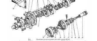
Basic parts of the D-260 diesel engine
Cylinder block D-260 The cylinder block of the D-260 engine of the MTZ-1221 tractor is the main body part and is made in the form of a monoblock; it is a rigid cast iron casting. Six removable sleeves made of special cast iron are installed in the block bores.
The liner is installed in the cylinder block along two centering belts. In the upper belt the liner is secured with a collar, in the lower belt it is sealed with two rubber rings placed in the grooves of the cylinder block.
Coolant circulates between the walls of the cylinder block and the liners. The transverse partitions of the cylinder block have bosses designed to form supports for the crankshaft. Covers are installed on these tides.
The bosses together with the covers form beds for the main bearings. The beds for the main bearing shells are bored from one installation complete with covers. Changing covers is not allowed.
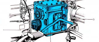
Diesel engine D-260 MMZ
1 – oil sump; 2 – oil pump; 3 – damper; 4 – crankshaft pulley; 5 – fan belt; 6 – distribution cover; 7 – tension pulley; 8 – nozzle for cooling the piston; 9 – fan; 10 – water pump; 11 – thermostat housing; 12 – connecting rod; 13 – piston; 14 – cylinder liner; 15 – cap; 16 cylinder head cover; 17 – cylinder head; 18 – cylinder block; 19 – back sheet; 20 – flywheel; 21 – crankshaft; 22 – oil receiver; 23 – camshaft.
The MTZ-1221 cylinder block has a longitudinal oil channel, from which oil is supplied through transverse channels to the main bearings of the crankshaft, and then to the camshaft journals and nozzles for cooling the pistons.
Piston cooling nozzles are installed in the cylinder block at the top of the second, fourth and sixth crankshaft bearings. On the water distribution channel of the cylinder block there is a platform for installing a liquid-oil heat exchanger. The supply and removal of oil from the heat exchanger is carried out through channels in the block.
To increase rigidity, the lower plane of the cylinder block of the D-260 engine is shifted downward by 80 mm relative to the axis of the crankshaft.
A steel distribution board and distribution cover are attached to the front end of the block, and a steel sheet is attached to the rear end, through which the diesel engine is connected to the frame of the MTZ-1221 tractor. The front support of the diesel engine is provided by two brackets mounted on the side surfaces of the cylinder block. The bottom of the cylinder block is closed by an oil sump.
Cylinder heads D-260
The D-260 cylinder head is cast from cast iron (one head for three cylinders) - interchangeable. In the internal cavities of the cylinder heads there are inlet and outlet channels closed by valves.
To ensure heat removal, the cylinder heads have internal cavities in which coolant circulates. The cylinder heads have inserted valve seats made of a heat-resistant and wear-resistant alloy.
The cylinder heads of the MTZ-1221 tractor are equipped with injectors (3 for each head), struts, rocker arm axles with rocker arms, head covers and cover caps that cover the valve mechanism. To seal the connector between the heads and the cylinder block, a gasket made of asbestos-free fabric is installed.
The holes for the cylinder liners and the oil channel are edged with sheet steel. When assembling a diesel engine, the cylinder holes of the gasket are additionally edged with fluoroplastic rings.
Checking the tightness of the bolts securing the D-260 cylinder heads
Fig. 1 — Diagram of the sequence of tightening the cylinder head bolts
Check the tightening of the cylinder head bolts of the D-260 engine of the MTZ-1221 tractor at the end of the run-in and after 1000 hours of operation on a warm diesel engine in the following sequence:
— remove the caps and cylinder head covers;
— remove the rocker arm axles with rocker arms and struts;
— using a torque wrench, tighten all the cylinder head bolts, having first loosened them by 1/6 of a turn, to a torque of 200:10 Nm in the sequence shown in Fig. 1.
After checking the tightness of the cylinder head bolts, replace the rocker arm axles and adjust the clearance between the rocker arms and the valves. Reinstall the cylinder head covers and caps.
Crank mechanism of the D-260 engine
General information and areas of application of "D-260"
The six cylinders of the MMZ D-260 engine are placed vertically in an in-line arrangement. The direction of rotation of the crankshaft is right (clockwise). The engine is four-stroke, equipped with direct fuel injection, liquid cooling, a turbocharging system and intercooling of charge air. Certified according to GOST-17.2.2.02, GOST-17.2.2.05, OST-23.3.23 and GOST-2000.
Depending on their purpose, diesel engines of this brand can be equipped with the following additional assembly units: a pneumatic compressor, a gear power steering pump with a drive, and clutch disc assemblies. When installed on a tractor, the MTZ “D-260” is equipped with a water radiator, electrical equipment and control devices.
"D-260" "under the hood" of the Belarus MTZ-1221 tractor.
Adjusting valve clearances
The clearances of the gas distribution valves are checked using the K-9918 device (Fig. 2), which consists of a housing 2 with a dial indicator 1 attached to it, a spring-loaded movable carriage 3 and a release cam.
There are two ways to check and adjust clearances.
In the first case, clarify the order of the intake and exhaust valves on the cylinder head using the diagram in Fig. 1.
Rice. 1. The order of the intake and exhaust valves on the D-260 engine
By turning the crankshaft with a handle and observing the pointer on the engine block and the scale on the cylindrical surface of the torsional vibration damper, ensure that the pointer coincides with the TDC mark on the scale, which corresponds to the TDC of the piston of the 1st cylinder (the end of the compression stroke in this cylinder). Using the release cam of the KI-9918 device (Fig. 4.14), move the movable carriage 3 to the lower position. Install the indicator / onto the device body and secure it with a locking screw with an interference fit of 0.2-0.3 mm. Install the KI-9918 device on the valve spring plate and use the release cam to move the plate to the upper position. In this case, the device must be clamped between the valve spring plate and the rocker arm, and the antennae of the movable plate are pressed against the rocker arm striker. Press the rocker arm with your finger until the striker stops at the end of the valve stem (Fig. 4.14) and set it on the indicator scale opposite the arrow, then release the rocker arm. Press the rocker arm all the way to the pusher rod, note the indicator readings and compare them with the nominal clearance values: exhaust - 0.40-0.45, intake - 0.25-0.30.
In the absence of the KI-9918 device, the gaps between the valves and rocker arms are checked with feeler gauges. To do this, use set No. 2 of 17 plates of varying thicknesses from 0.02 to 0.5 mm.
After checking and adjusting the valve clearances of the first cylinder, the valve clearances of other cylinders are checked in accordance with the order of their operation: 1-5-3-6-2-4, - turning the crankshaft by 120 degrees before each adjustment. During TO-3, before adjusting the thermal clearances of the gas distribution mechanism, check and, after removing the covers, tighten the cylinder head fastening nuts. First check the tightness of the nuts that can be accessed. If the nuts are turned at a tightening torque of 160-180 nm, tighten all the nuts by removing the gas distribution mechanism from the head, and tighten the nuts with a torque wrench from the middle of the head, alternately tightening the lying nuts crosswise and evenly moving away from the middle to the edges of the head.
Rice. 2. Measuring the gap between the valve stem and the rocker arm using the KI-9918 device: “1 - dial indicator; 2 - body: 3 - spring-loaded movable carriage; 4 - rocker arm
Valve clearances can be adjusted in another way. To do this, it is necessary to achieve valve overlap in the first cylinder (the intake begins to open, the exhaust finishes closing). In this position, the gaps are adjusted in the following order: 3, 5, 7, 10, 11, 12 (counting from the engine fan - Fig. 4.13). After turning the crankshaft one revolution, adjust the clearances in valves 1, 2, 4, 6, 8, 9.
The head fastening must be checked:
— when replacing the cylinder head gasket.
News
Replacement of fuel injection pump on MMZ D-260.4, D-260.4S, D-260.3 engines
The breakdown of any equipment is one of the unpleasant moments that stops the work process. The most expensive repair is engine maintenance. In order to avoid getting into a difficult and “expensive” situation, it is necessary to diagnose and repair failed parts in advance.
One of the common causes of unstable engine operation is the failure of the high pressure fuel pump.
In this article we will look at the injection pump 365.1111005-40.04 of the Compact 32 family, its analogues and the procedure for replacing it.
A high-pressure fuel pump is one of the important elements of the engine, responsible for supplying precisely measured portions of fuel to the cylinders at a certain pressure and at a certain point in the cycle, corresponding to a given load applied to the crankshaft.
Fuel injection pump 365.1111005-40.04 of the Compact 32 family is a high-pressure fuel pump with a vertical in-line arrangement of plunger pairs, the number of sections is 6, the intersectional distance is 32 mm. This high pressure fuel pump is used for diesel engines with a cylinder capacity of up to 1.5 liters and a power of up to 30 kW per cylinder. Fuel injection pump 365.1111005-40.04 allows for cyclic flow up to 160 mm and fuel injection pressure from 450 to 1100 ba. They are equipped with a mechanical all-mode and single-mode speed controller. The external speed characteristics of the engine are formed by a forward, reverse, and boost corrector.
High-pressure fuel pump 363.1111005-40.04 manufactured by YaZDA OJSC (YaMZ), Yaroslavl, is used on the following types of equipment:
— Combine harvester "Gomselmash" KSK-100A with MMZ D-260.4 D-260.4S2 engine,
— Belarus-2022 tractor with MMZ D-260.4 D-260.4S2 engine,
EURO fuel injection pump 1 363.1111005-40.0 is interchangeable:
— High pressure fuel pump TNVD 632.1111007-24 NZTA Noginsk (D-260.4S)
— High pressure fuel pump injection pump RR6M10R1f-3493 Motorpal Czech Republic (D-260.3)
The procedure for replacing the MOTORPAL injection pump with the NZTA injection pump, YaMZ OJSC:
Work on reinstalling pumps should be carried out on an engine that has been cleared of dust and dirt and thoroughly washed.
The iron horse is not a plowman, not a blacksmith, not a carpenter, but the first worker in the village.
Adjusting MTZ valves: work procedure, adjusting the gas distribution mechanism
Adjusting valves at MTZ is included in the list of routine operations carried out when servicing agricultural machinery. The ease of starting, stability of operation and thermal operating conditions of the power plant depend on the correct setting. The manufacturer recommends performing the adjustment after running in the engine (new or after a major overhaul), and then repeating the procedure after 240-480 hours of operation (depending on the modification of the machine) or during maintenance-2.
Adjustment procedure
By adjustment we mean ensuring a regulated gap between the plane of the rocker arm striker and the end of the air intake and exhaust gas exhaust valves into the exhaust manifold. The setting sequence and parameters depend on the modification of the power unit and the method of supplying air to the combustion chamber. Additionally, the tightness of the nuts securing the head to the cylinder block is checked, which reduces the likelihood of gasket breakdown and warping of the part due to uneven thermal deformations.
Preparing for adjustment
In preparation for tuning, you need to remove the sidewalls and fold back the hood cover , and then unscrew the fastening nuts and dismantle the protective metal casing covering the parts of the gas distribution mechanism on the diesel head. First, dust and oil deposits are removed from the surface of the part with a rag soaked in kerosene or diesel fuel. Then you need to check the tightness of the bolts securing the shaft on which the rocker arms are mounted.
Installing the cylinder piston TDC for adjustment
To set the piston of the first cylinder to the upper position of the “ compression stroke ”, it is necessary to turn the crankshaft manually until the intake valve begins to open. In this case, the exhaust valve should stop moving upward and close. The crankshaft is turned using a wrench, which is placed on the nut securing the auxiliary drive pulley.
On early models of D-240 power units equipped with a mechanical fuel pump, the injector can be unscrewed. The top position of the piston is determined by a pin lowered into the hole. When reinstalling the spray assembly, the O-rings must be replaced. Another technique is based on removing the fuel supply tube from the pump. When the top point is reached, fuel will begin to flow from the plunger pair. The technique is not accurate, since fuel injection begins early (before the piston reaches TDC).
On atmospheric 4-cylinder power units D-50 installed on MTZ-50/52 tractors, the flywheel housing has a through channel with a thread into which an installation pin is screwed (stored in a special channel on the crankcase). The stud has a non-threaded section with a rounded head that aligns with a recess made in the flywheel body. The technique allows you to accurately set the upper position of the first piston.
Setting the thermal gap
To maintain the distance, you will need to unscrew the nut holding the valve rocker arm adjusting screw from turning spontaneously. Then you should change the parameter by rotating the screw with a screwdriver; the adjustment stops after reaching a distance of 0.25 mm (the same for inlet and outlet). Then you need to tighten the nut with a wrench and additionally check the value of the gap in the valve pin-valve stem pair. The distance for the remaining valves is adjusted in the same way. After turning the shaft a full turn, it is necessary to adjust the remaining rocker arms.
It is allowed to use a special indicator device KI9918 for adjustment, which is mounted on the operating spring plate of the selected valve when the device carriage is raised to the top position (all the way). Then the rocker is combined with the measuring rod, which allows you to set the zero value on the scale of the dial gauge. Retracting the rocker arm until it contacts the drive rod allows you to determine the current value of the working distance between the elements. Then the parameter is set by rotating the screw on the rocker arm.
Projects on the topic:
The connecting rod of the D MMZ engine is steel, I-section.
The spherical part that goes inside the pusher and the rod cup are hardened. The list of clients includes over 44 enterprises located in Russia, Ukraine, Poland, etc. Turn the crankshaft for s for each line and tighten the union nut without stopping turning. Sealing collars installed on the valve guides prevent oil from entering the diesel cylinders through the gaps between the valve stems and the guides. The camshaft cams are made with a slight slope, due to which the pushers perform a rotational movement during operation.
The tightening torque should be 16-18 kgf-m - Nm; d after checking the tightness of the cylinder head nuts, reinstall the rocker shaft and adjust the gap between the rocker arms and the valves. Disassemble the motor. What is the procedure for tightening the main journals d 260 MTZ 1221!?
About the history of the enterprise and the MMZ D-260 engine
The history of the Minsk Motor Plant is closely connected with the history of another glorious Belarusian enterprise - the Minsk Tractor Plant. Built immediately after the Great Patriotic War, MTZ rapidly developed and increased its production. In 1960, a decision was made to build a plant for the production of diesel engines in Minsk. First of all, for the new model of the MTZ-50 tractor, in the amount of 120 thousand D-50 engines per year.
The Minsk Motor Plant was built in just over two years, on the north-eastern outskirts of Minsk between the tractor and bearing factories. Serial production of D-50 motors started at the enterprise in July 1963. Starting next year, all MTZ Belarus tractors began to be equipped with Minsk-made engines.
Alexander Lukashenko is a frequent guest at Belarusian enterprises, including MMZ.
In total, the list of MMZ partner enterprises, which are consumers of its products, includes 44 factories and firms. Most of them, of course, are in Russia and Belarus; Ukraine, Uzbekistan, Kazakhstan and Poland are also represented.