KAMAZ does not pump air
KAMAZ 65221, Compressor and its small defect)
Compressor ZIL. Valve plate repair
Secrets of the old KAMAZ driver. Quiz. Question 3.
Two-cylinder compressor, head repair and ring replacement
Single cylinder compressor KamAZ
Assembly of single-cylinder KAMAZ compressor (K-D) Product certified 53205-3509015
Consequences of incorrect installation of a single-cylinder compressor on an old KamAZ
How the body lift control crane should work on a KAMAZ dump truck
KamAZ 53504 does not pump air, and a little about the air system
Currently produced compressor equipment is reliable and durable. Despite the fact that the basis is the same units, thanks to modern developments and technical progress, dramatic changes have occurred for the better. The equipment has become more compact, while maintaining the same power.
The use of innovative materials has made it possible to increase the service life of most parts. To extend the life of spare parts, lubricating fluids are used, to which special additives are added. For control, most compressor models use a control panel, which can easily start and stop the unit. All information about the time worked and the amount of compressed medium produced is displayed on the console. In some models, information about possible problems is displayed on the display.
Unlike industrial compressor equipment, household models also have various sensors, but there is no remote control on which all the information is displayed, which most often creates a problem. For example, if a temperature sensor receives a signal about a slight deviation from the normal temperature, it signals a malfunction and stops the engine. This case is quite complicated, since it is not easy to find out what kind of problem is reducing the temperature readings.
There are four main malfunctions that lead to malfunction of brake systems:
– malfunction of the protective valves, – clogging or looseness of receivers, pipelines and hoses, – improper operation of piston rings and sensors, – compressed air leakage.
In order to prevent possible malfunctions in the KAMAZ brake system, it is necessary to check the operation of its systems in a timely manner. This can be done once every two years. So, below is a list of possible defects in the KAMAZ brake system and methods for eliminating it.
There is a lot of oil in the pneumatic system.
Wear of piston rings. Remedy: replace the compressor.
Receivers of circuit 1, 2 and 3 are not filled with air.
Cause: The supply tubes are clogged. Elimination method: simply blow out the tubes, and if foreign objects are found there, remove them. Cause: The safety valve is broken. Remedy: change the valve.
Pneumatic system receivers fill very slowly or do not fill at all.
Cause: Tubes, hoses or adapter and connecting equipment are not tightened sufficiently. Remedy: Tighten the places where the parts are connected; if necessary, replace the uncorrected parts. Reason: the receiver or device is not hermetically sealed. Remedy: change the receiver or device. Cause: The air supply hoses and tubes are damaged. Remedy: change hose and tube assemblies. Cause: Compressor performance is low Remedy: Check the compressor if it needs to be replaced. Reason: presence of dents on the surface of the outlet or air supply bosses. It is noticeable to a significant extent that the surfaces are not perpendicular to the axes of the holes in the threads. Remedy: Sand out small nicks and dents. Remove the problem of non-perpendicularity.
In the receivers of circuits 1 and 2, over or underpressure is observed when the pressure regulator is operating.
Cause: The pressure regulator is not adjusted correctly. Remedy: make adjustments using the adjusting screw, change the regulator as necessary. Cause: broken 2-pointer pressure gauge. Remedy: change the pressure gauge.
The car brakes poorly or there is no braking when the brake pedal is pressed.
Cause: Compressed air leak. Remove air leak.
Poor braking of the vehicle or lack of braking.
The prerequisite is that the circuit 3 hoses or tubes are clogged. Remedy: clean the tubes and then blow them with compressed air. If necessary, change it. Reason: spring energy batteries do not work. Remedy: change the spring energy accumulator and brake chamber. Cause: The relay valve is faulty. Remedy: replace faulty parts. Reason: increase in the stroke rate of the brake chamber rods. Remedy: adjust the stroke of the rods
Pull towards the vehicle when braking.
Cause: The brake pad linings of the brakes are oily. Remedy: change or wash the brake pad linings. Cause: The brake mechanism is poorly adjusted. Remedy: Adjust the rod output.
Source: www.tankdiv.ru
Reasons why the compressor does not gain pressure
Regardless of the reliability of compressors, problems and breakdowns may occur during long-term operation. One of the most common problems is that the unit stops pumping the compressed medium. Owners of diesel-powered screw compressors usually do not know what to do in this case.
After some time has passed since the unit was put into operation, such a problem may occur. In this case, the equipment cannot obtain the required pressure. There can be many reasons for this. One of the options is incorrect settings of the pressure regulators. If they are not broken, then a thorough inspection of the entire unit is necessary. First you need to check the locations of the inlet connections of the pipes to the receiver and the outlet threaded connections of the cylinder. Vibration could cause these components to become loose, which would consequently cause low pressure.
There are several other options in which the compressor simply cannot raise the pressure to the required level, which causes equipment failure:
- air leakage at the threaded connection of the pressure gauge and relief valve;
- a loose overpressure relief valve.
Fixing this problem is quite easy. It is enough to tighten the couplings tightly with a wrench of the appropriate size. Sometimes you need to replace the gasket or make a winding.
If such a check does not produce results, since all threaded connections are screwed tightly, air is not leaking through them, but the pressure continues to remain low, then you need to perform the following steps. Turn on the compressor, make a soap solution, which coats all connections. If there is an air leak somewhere, then bubbles immediately form at this place. Since the operating unit is very noisy, it is impossible to hear the air escaping from the fistula, but in this way it is clearly visible where there is a gap.
Sometimes a diesel screw compressor cannot pump out the required pressure due to worn-out compression rings. They need to be replaced, since these parts and the piston have an established working life. If such a replacement is not made, then first there is a lack of pressure, and then the power of the entire installation drops.
If, when treating with a soap solution, air is leaking under the cylinder and its head, then it is best to contact specialists who repair screw compressors. A fistula formed in this hard-to-reach place most often becomes the cause of low pressure and malfunctioning equipment.
You can repair this unit yourself. First, remove the casing, then unscrew the nuts connecting the body and cylinder head. In some cases, a stud is unscrewed instead of a nut. When reassembling, you will need to put them in place and tighten them with nuts. After lifting the cylinder head, you can see the gasket. If there is a break in the wall, then a replacement must be made. Some models of compressor equipment are equipped with a set of gaskets or they can be purchased at a special store.
To watch online, click on the video ⤵
The KAMAZ does not pump air. Reason. More details
KamAZ 53504 does not pump air, and little about the air system Read more
Kamaz Euro 4 does not pump the compressor. More details
KamAZ EURO pumps the air compressor very poorly Read more
Secrets of an old KAMAZ driver. Quiz. Question 3. Read more
KamAZ 65117 did not pump air or connect the cab part 2 Read more
AIR LEAVES THROUGH THE KAMAZ ACCELERATING VALVE. HIT WHEN REMOVED FROM THE HANDBRAKE. More details
Does not pump air into the circuit zil 5301 bull Read more
Why does the pressure gauge indicate different pressures Read more
Triple and double protection, how it works and how it can be simplified Read more
Two-cylinder compressor, head repair and ring replacement Read more
Brake system KAMAZ More details
How to simply pump oil on a KAMAZ) Read more
Air leak from the brake valve KAMAZ ZIL PAZ MAZ KRAZ GAZ Read more
Everyday life of a Kamaz driver: we start the car in the winter at – 3, after a week of parking Read more
Vlog without editing. How to properly pump air into the pneumatic system of KAMAZ 5511. 5 Read more
Pneumatic braking system Read more
Air dryer for MAZ, KAMAZ 1 part. More details
Why does a trailer take a long time to release the handbrake More details
Source: putinizm.ru
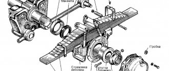
Design and mechanism of operation
The design of this mechanism contains such parts as:
- unloading piston and valve;
- air flow sampling plug;
- release type valve;
- spring mechanism;
- balancing device;
- adjusting screw;
- case;
- follower type piston;
- check valve;
- unloading mechanism saddle;
- cap;
- atmospheric findings;
- filter and pusher.
The flow of compressed air from the compressor system through the output of the control mechanism, filter elements and valves enters the receivers of the car's pneumatic system.
How to install
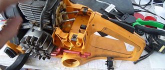
After replacing parts, the compressor must be installed back. To do this you should:
- Place the connecting rod in a vice, press in the bushing and pin, lubricating it with oil
- Place the rings, remove the part from the vice
- Attach head, seat gaskets, valves, springs
- Screw in the plugs
- Press in the crankshaft with oil seals, install thrust rings
- Install the gear and lock washer
- Pull the cover with gasket onto the crankcase, secure with bolts
- Blow with compressed air
- Press intake valves and guides into the cylinder block
- Install the unit head on the block, tighten with nuts
How to adjust air pressure
In order to adjust the air pressure, you need to install the vehicle on an inspection hole or a special platform for repair work.
Adjustment of the mechanism is carried out only when the power unit is turned off.
The whole process takes place in 3 steps: disassembly, adjustment and installation.
In order to dismantle the regulator, it is necessary to unscrew the lock nut and unscrew the adjusting screw. This will help loosen the counterbalance type piston springs. After this, use a special socket wrench to remove the spring device, unscrew the protective cover and remove the sealing collar.
In order to remove the muffler, you need to unscrew the fasteners from the bottom of the cover and remove the filter element. Then you should remove 2 o-rings and the unloading piston. After dismantling, it is recommended to wash all parts with clean gasoline.
After the above steps, you should install the regulator on a special test panel and connect the device according to the diagram given in the user manual.
After connecting, you need to apply compressed air at a pressure of at least 1.4 MPa to the terminals 3 times.
In this case, if the limits of the regulated pressure exceed 0.8 MPa, it is necessary to adjust the pressure level to the required limits using a bolt.
Upon completion of the adjustment, you should check the level of pressure on and off the regulator 3 times, after which you can lock the bolt.
Compressor parts defective
In the event of defect detection, parts with cracks, chips, burrs, scratches on working surfaces, and other mechanical damage are subject to rejection.
| Size | Diameter cylinder, mm | Marking |
| Nominal | 60+0,03 | 0 |
| 1st repair | 60,4+0,03 | +0,4 |
| 2nd repair | 60,8+0,03 | +0,8 |
If the inner surface of the cylinders is worn by more than 0.02 mm, it is necessary to bore the cylinders to the repair size (Table 1). The seat diameter under the intake valve seat should not exceed 17.027 mm.
The diameter for ball bearings in the compressor crankcase should be no more than 72.05 mm.
With a larger diameter, an interference fit of the bearing is not ensured.
The non-flatness of the contact surface of the compressor head to the cylinder block should be no more than 0.1 mm.
Risks and wear marks on the surface of the discharge valve seats are eliminated by grinding and lapping the valves.
The diameter of the hole for installing the discharge valve must be no more than 28.8 mm.
| Size | Diameter connecting rod necks, mm | Marking |
| Nominal | 28,5-0,021 | 0 |
| 1st repair | 28,2-0,021 | -0,3 |
| 2nd repair | 27,9-0,021 | -0,6 |
The diameter of the crankshaft for ball bearings and gears must be at least 35 mm, for the mechanical seal no more than 25.05 mm, and the width of the keyway no more than 5.02 mm.
When the connecting rod journals wear out, they must be ground to the next repair size (Table 3).
| Group | Hole diameter under your finger in the sleeve, mm | Color markings |
| I | 12,507…12.504 | White |
| II | 12,504…12,501 | Green |
| III | 12,501…12.498 | Blue |
| IV | 12,498…12,496 | Red |
The non-parallelism of the axes of the holes in the upper and lower heads of the connecting rod (bending) over a length of 100 mm should be no more than 0.1 mm.
The misalignment of the axes of the holes of the upper and lower heads (twisting) over a length of 100 mm should be no more than 0.15 mm.
The diameter of the lower head of the connecting rod should be no more than 32.02 mm, and the diameter of the bushing of the upper head should not be more than 12.507 mm.
If the upper head bushing is loose, it must be replaced.
When replacing, an lubrication hole must be drilled in the bushing and the bushing must be turned to the nominal size.
The connecting rods are divided into groups at 0.003 mm intervals according to the smaller hole diameter and are marked with paint (Table 4).
| Size | Piston diameter, mm | marking | |
| At the skirt | At the bottom | ||
| Nominal | 59,9-0,03 | 59,8-0,03 | — |
| 1st repair | 60,3-0,03 | 60,2-0,095 | +0,4 |
| 2nd repair | 60,7-0,06 | 60,6-0,195 | +0,8 |
The height of the discharge valve plug must be at least 31.1 mm.
The seat diameter of the seal is at least 24.94 mm.
For the compressor drive gear, the tooth thickness along the chord of the pitch circle must be at least 4.2 mm, and along the width of the keyway no more than 5.15 mm.
| Group | Hole diameter under your finger in the piston boss (finger diameter) | Color markings |
| I | 12,500… 12,497 | White |
| II | 12,497.. .12,494 | Green |
| III | 12,494.. .12,491 | Blue |
| IV | 12,491… 12,488 | Red |
Wear of the piston at the bottom and skirt by more than 0.015 mm from the nominal or repair size is not allowed (Table 5).
Repair size pistons are marked on the outer surface of the bottom. The diameter of the hole in the piston boss for the pin is allowed to be no more than 12.5 mm.
Based on the diameter of the hole in the boss, the pistons are divided into groups every 0.003 mm (Table 6).
The diameter of the piston pin must be at least 12.488 mm. Fingers are sorted into groups by diameter.
The sizes and markings by group correspond to the sizes and markings for pistons (see Table 6).
Wear of the liner by more than 0.01 mm from the nominal or repair size is not allowed (Table 7).
| Size | Thickness, mm | Marking |
| Nominal | 1,75-0,013 | — |
| 1st repair | 1,90-0,013 | -0,3 |
| 2nd repair | 2,0,5-0,013 | -0,6 |
When checking, piston rings are installed in ring gauges.
The gap in the lock of the piston ring installed in the caliber must be within 0.2 ... 0.6 mm.
Ring repair kits are marked with green paint; the diameters of the gauges for checking the rings are given in Table 8.
| Size | Diameter caliber, mm | Ring markings |
| Nominal | 60 | Not marked |
| 1st repair | 60,4 | One strip 10 mm wide |
| 2nd repair | 60,8 | Two strips 10 mm wide |
Malfunctions and repairs
Main malfunctions and repairs of the regulator:
- If air leaks through the atmospheric outlet, you need to clean the valve body or replace the faulty valve and O-ring.
- The device has finished switching the compressor to idle mode. This problem can be caused by clogging of the channel, jamming of the piston, or damage to the cuff. It is recommended to clean the valve, conduct an external inspection of the cuff and, if necessary, change it to a new one, and also update the piston.
- The regulator has finished switching the compressor to the mode of filling the system with air. This malfunction is associated with clogging of the atmospheric orifice and intake valve, a warped spring, a worn O-ring, tightness of the piston part and wear of the valves. It is necessary to carry out an external inspection of the entire system for damage and defects, and replace failed spare parts as necessary.
- Air leakage through the outlet into the atmosphere can be eliminated by replacing the filter element.
- When there is no supply of compressed air flow to the brake system of a vehicle, it is necessary to clean the return valve from accumulated contaminants or replace it if worn.
- If there is a small shaft between the on and off pressure levels of the control device, you should change the warped cuffs and rings, inspect and clean the valves and seats.
All repair work is carried out only with the engine turned off.
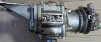
KAMAZ compressor diagnostics
It is recommended to carry out a preventive inspection of the vehicle compressor at every maintenance. For KAMAZ it is carried out every 8-10 thousand kilometers.
The supercharger is inspected for the presence of external defects, the supply pressure is checked (the norm is from 589 kPa), the tightness of the valves (determined by the level of pressure drop in 60 seconds, the norm is up to 39 kPa), and oil release.
If deviations from normal values occur, the compressor is troubleshooted and the faults are eliminated.
Return to list
Reviews and prices
The average cost of the Russian Far East is 4,500 rubles.
Misha, 36 years old, Izhevsk: “I have been working as a KamAZ driver for 6 years. Over the course of its operation, the air pressure regulator in the pneumatic system failed a couple of times. On average, repairs take about one to two days. In order for the mechanism to break down less often, I recommend using high-quality fuel.”
Alexander, 49 years old, Lipetsk: “I work in a service center. Cars are often brought in for repairs with a non-functioning air pressure regulator. This mechanism fails if maintenance is not carried out on time and the oil in the system is not frequently changed. I also recommend cleaning the filters at least once a month.”
Evgeniy, 53 years old, Voronezh: “I work at KamAZ 45143. The regulator failed only 2 years after the start of operation of the vehicle. At first, an air leak began, and later the device finished switching the compressor to a suitable operating mode. I did the repairs without the help of others according to the instructions, no difficulties arose.”
Konstantin, 46 years old, Leninsk: “In order to repair the regulator, I recommend using a special device that helps adjust the pressure level. Before connecting equipment to this device, it is necessary to perform an external inspection of the regulator for the presence of any damage or defects.”
Peter, 50 years old, Krasnodar: “I have repaired the regulator at KamAZ 3 times already. The cause of failure is always clogged filter parts and warped cuffs. In order to avoid defects, I recommend changing the O-rings once every 3 months and frequently carrying out technical maintenance of the vehicle.”
Possible malfunctions of the brake systems of KamAZ vehicles are given in Table 12.2
Table 12.2 – Possible malfunctions of brake systems
| Cause of malfunction | Elimination method |
| 1. The pneumatic system receivers are not filled or are filled slowly. The pressure regulator does not work | |
| Damage to air supply hoses and tubes | Change hoses and tubes |
| Insufficient tightening at the joints of tubes, hoses, connecting and transition fittings | Tighten connections Replace faulty connection parts and seals |
| The presence of nicks and dents on the end surfaces of the compressed air supply (discharge) bosses. Significant non-perpendicularity of the end surfaces relative to the axes of the threaded holes | Sand small nicks, dents, remove non-perpendicularity |
| Leakage of the receiver, device | Change receiver, device |
| Reduced compressor performance | Check the compressor, replace if necessary |
| 2. The pressure regulator often operates when the pneumatic system is filled with air. | |
| Leakage of compressed air in the line from the pressure regulator to the safety valve | Remove the leak using the methods indicated in paragraph 1 |
| 3. The pneumatic system receivers are not filled with air. The pressure regulator is activated | |
| Incorrect pressure regulator adjustment | Adjust the pressure regulator using the adjusting screw. Change the regulator as necessary |
| Clogged tubes in the area from the pressure regulator to the safety valve | Inspect the tubes, if necessary, remove and blow out. If the tube is incorrectly bent (there is a kink), change it |
| 4. Receivers of circuits I, II or III are not filled with air | |
| Safety valve malfunction | Replace a faulty device |
| Clogged supply tubes | Blow out the tubes. If there are foreign objects in the tubes, remove them |
| 5. Trailer receivers are not filled with air | |
| Malfunction of trailer brake system control devices located on the tractor; trailer brakes | Replace a faulty device |
| Clogged supply tubes | Blow out the tubes If there are foreign objects in the tubes, remove them |
| 6. The pressure in the receivers of circuits I and II is higher or lower than normal when the pressure regulator is working | |
| Malfunction of two-pointer pressure gauge | Change the pressure gauge |
| Incorrect pressure regulator adjustment | Adjust the regulator using the adjusting screw. If necessary, change the regulator |
| 7. Ineffective braking or lack of braking of the vehicle by the working brake system when the pedal is fully depressed | |
| Brake valve malfunction | Change the brake valve |
| Contamination of the cavity under the lever covers of the two-section brake valve. Rupture or removal of covers from the seat | Clean the cavities from dirt. Change covers if they are unsuitable |
| Relay valve malfunction | Change the accelerator valve |
| Significant leakage of compressed air in the lines of circuits I and II in the area after the brake valve | Remove the leak using the methods indicated in paragraph 1 |
| Improper adjustment of the brake valve | Adjust the brake valve |
| Exceeding the permissible stroke of the brake chamber rods | Adjust the stroke of the rods |
| Water on brake pads | Dry the brake mechanisms with several brakes. |
| Jamming of expansion fist shafts | Clean and lubricate the expansion knuckle shaft bushings |
| Brake lining wear | Change |
| 8. Ineffective braking or lack of braking of the vehicle by the parking brake system | |
| Accelerator valve malfunction; parking brake control valve | Replace faulty devices |
| Clogged tubes or hoses of circuit III | Clean the tubes and blow them out with compressed air. Replace with serviceable ones as necessary. |
| Malfunction of spring energy accumulators | Replace a faulty brake chamber with a spring energy accumulator |
| Exceeding the permissible stroke of the brake chamber rods | Adjust the stroke of the rods |
| 9. When installing the handle of the parking brake system control valve in a horizontal position, the car does not release the brakes | |
| Air leakage from the tubes of circuit III, from the atmospheric outlet of the accelerator valve | Remove the leak using the methods indicated in paragraph 1 |
| Failure of the spring energy accumulator | Replace a faulty brake chamber with a spring energy accumulator |
| Jamming of expansion fist shafts | Lubricate the shaft bushings |
| 10. When the vehicle is moving, the rear cart is braked without actuating the brake pedal and the parking brake system control valve | |
| Malfunction of two-section brake valve | Change the faucet |
| Incorrect brake valve adjustment | Adjust the tap |
| Failure of the seal between the cavity of the energy accumulator and the working chamber of the spring | Replace a faulty brake chamber with a spring energy accumulator |
| 11. Ineffective trailer braking or lack of braking when the brake pedal is pressed or the parking brake system control valve is turned on | |
| Compressed air leak | Remove the leak using the methods indicated in paragraph 1 |
| Malfunction of subsequent drive devices: single safety valve, trailer brake control valve with a single-line drive, trailer brake control valve with a two-line drive, connecting heads, line filters, combined trailer brake air distributor | Replace faulty devices |
| Exceeding the permissible stroke of the trailer brake chamber rods | Adjust the stroke of the rods |
| Brake chamber membrane rupture | Change the membrane |
| 12. The brake mechanisms do not release when the trailer brake release valve button is pulled out | |
| Malfunction of the trailer brake release valve | change the tap |
| 13. When you press the brake pedal when actuating the parking brake system control valve, the brake lights do not light up | |
| Malfunction of the brake signal switches or pneumatic drive devices | Replace faulty switches or devices |
| 14. Presence of a significant amount of oil in the pneumatic system | |
| Compressor piston ring wear | Change the compressor |
| 15. When braking, the car pulls to the side | |
| The adjustment of the brake devices is incorrect | Adjust the output of the rods |
| Oiling of brake pad linings of individual brake devices | Wash the pads or change them |