The use of electronic control and diagnostic systems is widespread in modern engines. Such systems greatly simplify troubleshooting inside a diesel engine.
It is enough just to connect the diagnostic equipment to the appropriate electronic connector, and all information about the engine condition will be on the screen.
In addition, many vehicles equipped with Cummins engines are equipped with a self-diagnosis system, thanks to which you can accurately determine the malfunction even without connecting third-party equipment.
However, in both cases, the interaction of electronic diagnostics with the operator is carried out using standard codes. In order to understand the diagnostic system signals, you need to know exactly what the Kamens engine error codes mean. To do this, you need to understand them in more detail.
How to diagnose
Diagnostics includes collecting signs of problems in the system, scanning the electronic control system, resetting and checking all mechanisms and systems for faults in the electronic unit, inspecting all sensors that are responsible for the uninterrupted operation of the power unit.
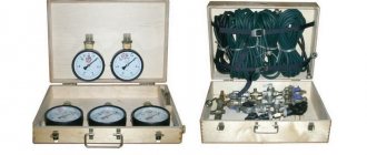
During diagnostics of KamAZ-5490, 54115, 5308 and other models with an engine manufactured according to the international environmental standards Euro-3 and 4, the pressure level in the fuel system is measured, the performance of the generator set is tested and exhaust gases are analyzed using special equipment. They also check the winding of the electromagnetic regulator of the fuel supply system and the short circuit in the inductive sensor coils.
Equipment and programs for diagnostics
There are several scanners for detecting problems in vehicle mechanisms, for example:
- Autoscanner DK-5. This equipment helps detect problems in the electronic unit by reading and adjusting control system indicators using a computer. This autoscanner can be used at temperatures up to +30°C and relative humidity no more than 80%.
- Scanner EDS-24. This is a software and hardware complex designed for computer diagnostics of a cargo vehicle. It includes a USB adapter with galvanic isolation, which makes it possible to test systems in low voltage conditions.
Diagnostic programs:
How to view KamAZ errors
To perform the check, use two methods.
- Diagnostics using BC. For each modification of the car, the sequence of actions and procedure may differ - you need to look in the service documentation. The advantage of the procedure is its ease of implementation. The disadvantages include inaccuracy of data.
- Connect an external diagnostic module to the car. This will allow you to accurately determine the cause of the problem. At the same time, special equipment and deep knowledge in the diagnosis of trucks will be required.
Cammens engine diagnostic system
Error codes or engine malfunctions are digital codes that are generated by the vehicle’s self-diagnosis system when a particular malfunction occurs.
Each code that occurs is recorded by the electronic control unit and stored in its memory. This allows you to track the history of the error and more accurately determine the cause of its occurrence. As a result, you can make faster and better repairs.
Electronic codes not only indicate engine malfunctions, but are also a purely informative function, giving an accurate idea of the processes occurring inside the engine or what is happening in the control system.
Codes can be active (those that report a current, unresolved error) and inactive (past errors that are stored in the memory of the electronic engine management system).
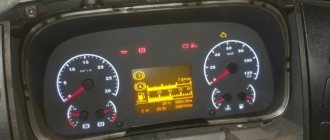
To successfully use the codes that the self-diagnosis system produces, you need to know exactly where to look for Kamens error codes. They are always on the control panel. Depending on the age of the car, they can be displayed either using indicator signals (LEDs) or on a digital display in the case of more modern cars.
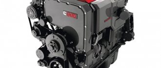
When replacing the alternator belt, before removing it, it is better to draw up a diagram of its location - this will greatly facilitate the procedure for installing a new belt.
A prerequisite on which the success of Kamens isf 3.8 repair depends is the timely detection of the malfunction. A decrease in power, difficult starting, characteristic instability in operation in various modes, an increase in specific fuel consumption and an increase in CO content are reasons for diagnostics. Details here.
In order to prioritize signals and warnings, they are illuminated with the usual three-color backlighting: green, yellow and red. The meaning of these colors is intuitive: red should be taken as an indication to stop the engine and immediately take action to eliminate the malfunction. Before this, starting the engine is prohibited.
Yellow color is a warning. Although it does not require immediate shutdown of the unit, the yellow indicator still signals the need to correct the malfunction as soon as possible.
The green color of the indicator does not indicate an error, but indicates the current state of the engine. This Cummins error code, highlighted in green, can indicate parameters such as coolant level and temperature, system oil temperature, air temperature, etc.
So, it's time to sum it up. The diagnostic system can signal the occurrence of a particular error:
- or by flashing indicator lights;
- or digital codes that appear on the display in more modern cars.
Accordingly, the driver’s actions will be different. Let's look at what needs to be done to clarify the meaning of the blinking lights.
Spn 4335 fmi 16 cummins error code
The turbocharger actuator position sensor uses a common power circuit and a common ground circuit in the engine wiring harness along with other sensors. Open circuits and shorts in the engine wiring harness can result in multiple active DTCs. Possible causes of this problem:
Possible power reduction. Power will be cut off from the turbocharger control motor. The turbocharger will operate in the open position.
The ECM monitors the voltage level in this circuit and sets a DTC when an open circuit or short to power is detected. This DTC becomes passive whenever
turning the starter switch to the ON position. If the cause of this code occurs repeatedly while the key switch is in the ON position, the code will become active. Since active fault codes become passive when the starter switch is turned to the ON position, this troubleshooting flowchart is used to diagnose active and passive codes. Possible causes of this problem:
Do not apply voltage of any kind to the turbocharger control motor. This circuit carries a pulse width modulated signal and applying DC current can cause permanent damage to the motor.
Decoding errors
The decoding of KamAZ error codes is presented in the instructions for the program, which is used for diagnostics. Examples of errors:
- 213 - malfunction of the power unit control device;
- 296 - oil pressure has dropped;
- 2973 - failures in the air pressure control system in the intake manifold;
- 214 - overheating of the oil fluid;
- 235 - insufficient amount of coolant in the system;
- 425 - high oil temperature;
- 3617 - there is no signal from the multi-stage switch;
- error 4335 - problems with air supply;
- 275 - fuel injection pump is not working correctly;
- 429 - high voltage in the fuel indicator circuit;
- 351 - malfunction of the injectors;
- 415 - low level of working fluid;
- 261 - fuel overheating.
Sensor failures
Fault codes for KamAZ-34334, 6308 and other models with Euro-4 engines:
- 221 - a breakdown in the pedal position sensor, which is responsible for the supply of working fluid;
- 232 - malfunction of the sensor measuring atmospheric pressure;
- 335 - defects in the wiring of the lamp control output stage;
- 231 - malfunction of the boost pressure sensor on the electrical control unit;
- 124 — fixing an incorrect voltage indicator;
- 345 - incorrect operation of signal transmission from the exhaust gas pressure indicator;
- 113 - problems with camshaft speed;
- 112 - incorrect indicators supplied to the control unit from the crankshaft;
- 246 - malfunction of the temperature sensor;
- 00550 - malfunction of the fuel injection pump plug.
Read more: How to clean the intake manifold
ICE malfunctions
List of internal combustion engine breakdowns on KamAZ:
- 726 FMI 2 - malfunction of the position indicator of the device responsible for liquid distribution;
- SPN 526313 FMI 6 - defective device that controls the pressure level in the ramp mechanism;
- SPN 520211 FMI 12 - no message from the ABS system;
- SPN 791 FMI 4 - low charge level;
- 523470-2 - there is no voltage in the circuit of the mechanism responsible for resetting the pressure indicators;
- SPN 523613 FMI 16 - working fluid filters are worn out;
- 77 FMI 0 - high engine speed;
- 190-3 - malfunction;
- 110-0 — high level of motor temperature;
- 132-4 - failure in air flow distribution;
- 653-0 - damage to the injector power supply system.
Other breakdowns
| System error codes | Cause of failure |
| SPN 977 FMI 4 | Malfunctions in the operation of the air conditioner chain mechanism |
| 98-1 | The number of crankshaft revolutions has been exceeded |
| 523601-4 | Low fuel and oil level |
| 3514-31 | The power supply has failed |
| 675-4 | Injectors are closed |
| 13688-4 | Fuel pump relay shorted to ground |
| 91-4 | Fuzzy signal from the sensor responsible for the position of the brake mechanism |
| 171-3 | This error stands for a malfunction of the thermometer |
| 1072-4 | The valve was shorted to ground |
| 111-3 | Strong signal from the antifreeze level indicator |
| 1188-5 | There is no connection with the air flow heating relay |
| 110-2 | The sensor monitoring the antifreeze temperature is not working correctly |
| 1188-4 | There is a short to ground in the pressure valve control circuit. |
What does the error consist of?
The first character is a letter that determines the type of defective system:
- P – malfunction of the power unit or transmission (automatic transmission).
- B – malfunctions in the operation of body systems - airbags, electric windows, central locking, etc.;
- C – malfunctions in the chassis of the vehicle;
- U – errors associated with the interaction of electronic modules.
The second character is a number that determines the specificity of the malfunction:
- 0 – general symbol for OBD block;
- 1 and 2 – personal codes of the car manufacturer;
- 3 – reserved information.
The third character determines the type of failure:
- 1 and 2 – air or fuel supply;
- 3 – ignition unit, system for detecting misfires of the air-fuel mixture;
- 4 – additional emission control mechanism;
- 5 – control of vehicle speed and idle speed;
- 6 – electronic control modules, as well as their wiring;
- 7, 8 – errors in the operation of the gearbox;
- 9, 0 - reserve.
How to reset errors
Resetting on KamAZ-4334, 5308 and other models can be done as follows:
- Warm up the engine to operating temperature.
- Remove the positive terminal from the battery for 5-15 minutes.
- Connect the terminal back to the battery.
- Turn the ignition key to the last position before starting the engine from the starter. In this case, the lights and indicators located on the dashboard should light up.
- Leave the key in this position for 1 minute.
- Return the ignition key to its original position.
If this does not help, then a short circuit should be made in the vehicle circuit. In this case, after resetting, you will have to replace the safety element.
This is an error in the neutralization unit. Increased air pressure. However, it is better for you to contact our dealer. He will find the error for you and fix it. At the same time, the guarantee will remain.
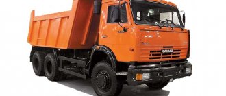
All errors KAMAZ 4307, 4308, 4311, 43255, 4350, 5308, 53215, 54115, 5460, 5490, 63698 Typhoon-K, 6460, 65111, 65115, 65117, 6520, 65201, 652 06, 65207, 6522, 65225, 6540, 6560, 6580, 65806.
What errors does the control unit produce on a KAMAZ 5490 vehicle?
The KAMAZ 5490 tractor belongs to the main truck type of vehicle. A German-made power unit is installed on board the truck. The Mercedes-Benz engine is capable of producing about 428 hp. The injection system with a PLD fuel mechanism ensures the efficiency of the engine. For 100 km of travel, the KAMAZ 5490 engine consumes about 33 liters of diesel fuel. The power unit installed in the car meets the requirements of the Euro 5 eco-standard. A characteristic feature is a comfortable European-style cabin, best suited for long journeys along highways: rubber mats on the floor, soft seats, refrigerator. For driver convenience, an electronic instrument panel with a touch screen is provided. Electrics KAMAZ 54901 operates at 24 V.
How to diagnose
Diagnostics includes collecting signs of problems in the system, scanning the electronic control system, resetting and checking all mechanisms and systems for faults in the electronic unit, inspecting all sensors that are responsible for the uninterrupted operation of the power unit.
During diagnostics of KamAZ-5490, 54115, 5308 and other models with an engine manufactured according to the international environmental standards Euro-3 and 4, the pressure level in the fuel system is measured, the performance of the generator set is tested and exhaust gases are analyzed using special equipment. They also check the winding of the electromagnetic regulator of the fuel supply system and the short circuit in the inductive sensor coils.
Equipment and programs for diagnostics
There are several scanners for detecting problems in vehicle mechanisms, for example:
- Autoscanner DK-5. This equipment helps detect problems in the electronic unit by reading and adjusting control system indicators using a computer. This autoscanner can be used at temperatures up to +30°C and relative humidity no more than 80%.
- Scanner EDS-24. This is a software and hardware complex designed for computer diagnostics of a cargo vehicle. It includes a USB adapter with galvanic isolation, which makes it possible to test systems in low voltage conditions.
Diagnostic programs:
Self-diagnosis
Self-diagnosis on BOSCH and ISB is slightly different. Knowing the error code, you can fix the problem yourself.
The diagnostic indicator light comes on when the engine is turned on; during normal operation it should turn off; if this does not happen, there is a problem.
To diagnose, you need to hold down the special button for 2 seconds. The diagnostic indicator will start flashing: first with large intervals, then with small ones. The photo shows how to identify the digital code:
The ISB ECU has 2 diagnostic indicators: red and yellow, indicating the severity of the fault. After pressing the button, as in the previous case, one of the indicators will start flashing. The error code for this ECU is 3 or 4 digit. Each digit (number) will be separated from the previous one by a pause of 2 seconds.
How to diagnose the error?
There are two ways to diagnose errors on KamAZ - using a computer, or using self-diagnosis.
Description of instructions for diagnosing a Bosch computer unit (Bosch) model MS 6.1:
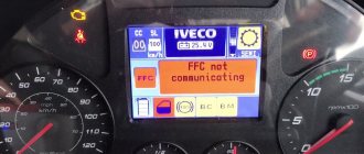
- The car's ignition is turned on. Icons will appear on the KamAZ Kamens (Cummins) dashboard, including the Check Engine (ICE) fault indicator. The symbol will appear for three seconds and then disappear. If the indicator does not turn off, then there is a malfunction in the operation of one of the systems or components.
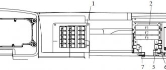
- Then you need to find a special diagnostic button; on most Kamins or Common Rail models it is located under the steering wheel on the center console. If this control element is missing, then you need to look for the key next to the safety module, opposite the passenger seat.
- The button has two extreme positions and one fixed position in the center. The control must be lowered down or raised up and then held for two seconds.
- The button should automatically return to its original state after the driver releases it. Then the diagnostic indicator will begin to blink, first at longer intervals, and then at short intervals. The number of blinks indicates the first fault category, and the number of short flashes indicates the second. You need to write down all the errors, after which you will need to decipher them.
Diagnosis of KamAZ error codes using a computer and program is performed as follows:
- The scanner or laptop is connected to the vehicle control unit via the OBD2 connector.
- The diagnostic equipment is activated. Depending on the requirements specified in the service manual, the ignition is activated or the engine starts.
- Then you need to start reading errors on KamAZ Cummins or another model. The diagnostic scan tool or computer should show error codes on the panel. You need to find and find out what these codes mean in the list of errors; repairs are carried out in accordance with the received designations.
Electronic control systems for KamAZ vehicles
An electronic control system regulates engine operation, its main function is to control the operation of the battery fuel system (common rail): it ensures precise dosing of injected fuel, which allows for economical consumption and reduces smoke levels, helping to control speed.
The ESU includes an electronic control unit (ECU), an injection pump solenoid, diagnostic mode and speed limiter switches, as well as many sensors.
Many KamAZ truck models are equipped with Cummins engines, for which Bosch electronic control systems are suitable. Models with Mercedes-Benz engines are equipped with the same ECS. Only 2 models are installed on KamAZ 6520: Bosch MS6.1 and ISB CM 2150.
Thanks to sensors, the ECS is able to report a malfunction. Each breakdown has its own code name. For example, errors in KamAZ 5490-s5 with a Mercedes engine indicate the location of the breakdown and the possible cause.
ECU BOSCH MS 6.1
Engines of Euro-3 class (KAMAZ 65115) and higher have an ECS with a control unit that provides electronic control of the injection pump.
BOSCH MS 6.1 processes signals from all ECS sensors, showing information about the engine condition. By analyzing the indicators of the sensors, the ECU influences the operation of the fuel injection pump rack, which is responsible for dosing the fuel fluid.
The control unit allows you to remotely adjust some parameters, for example, change the maximum possible speed, etc. It also receives signals about malfunctions, showing a specific code indicating a particular breakdown.
ECU ISB CM 2150
The ISB CM 2150 ECU is required to control the Cummins engine. Suitable for ISBe, ISDe, ISLe. KamAZ 43118 is available with a Cummins ISLe engine, for which the ISB CM 2150 is suitable.
Just like the Bosch control unit, ISB allows you to remotely regulate the fuel supply and displays information about the malfunction in the form of error codes.
How to diagnose faults on a KAMAZ truck?
Is a serious vehicle exhibiting inappropriate behavior? The vagaries of your truck can ruin business deals and lead to long periods of downtime, draining your wallet. In this article, we will tell you how to diagnose problems at an early stage in order to begin troubleshooting problems in a timely manner.
Recently, engines from the Kama Automobile Plant began to be classified according to their belonging to one or another environmental class (from Euro-0 to Euro-4). The technical implementation of the Euro-3 class, and then Euro-4, adopted in 2013, turned out to be impossible without the use of electronic engine control systems (ECM). This is what led to the opportunity to perform self-diagnosis of the car using KAMAZ universal error codes.
Ecological class Euro-4
Various configurations of KAMAZ trucks began to be equipped with engines with electronic control units (ECU). And if now the driver is concerned about unhealthy behavior during the operation of famous trucks, symptoms appear in the form of floating speed, loss of traction, unusual noises, increased diesel fuel consumption, self-diagnosis comes to the rescue.
Using information output from the ECU in the form of an error code, it is possible to indicate an accurate electrical diagnosis for KAMAZ. The process of diagnosing and deciphering codes depends on the type of electronic system installed on the truck. Before starting diagnostics, it is suggested to determine the type of ECU based on the installed engine model.
Engine Model Table
Self-Diagnostics No matter what company your V8 is made by, Cummins Inc. (Cummins) or KAMAZ LLC, it is equipped with fuel supply systems from Common Rail and exhaust gas recirculation (EGR) or neutralization systems (SCR), diagnostics will be carried out in accordance with these two types.
The process of self-diagnosis of KAMAZ electronic systems in Euro-3, -4 engines differs slightly from a similar procedure in other vehicles. After pressing a certain button, one of the lamps on the dashboard or indicator unit will begin to blink at different intervals; the number of flashes of the lamp at one interval determines the digit of the code.
Engine with ECU BOSCH MS 6.1
So, let’s get comfortable in the cabin of our KAMAZ, then turn on the ignition with the usual turn of the key. Along with many other indicators, the diagnostic indicator light or “Check Engine”, or in common parlance, a submarine, lights up. The lamp lights up for 3 seconds and goes out, thereby demonstrating its functionality and the serviceability of the ECM. If the lamp does not go out or lights up while the engine is running, a malfunction has been found in the electronic system!
Diagnostic indicator lamp
Let's pay attention to the diagnostic mode rocker button (often mounted on the instrument panel on the left, under the steering wheel) or the button for this mode (often located next to the fuse box, under the panel opposite the passenger seat). The “rocker” has two extreme positions for holding and a central fixed position.
Diagnostic mode rocker button Diagnostic mode button
Lower the rocker to its highest or lowest position and hold it there for more than two seconds. Just press the button and do not release it for the above-mentioned time. After the rocker or button returns back, the diagnostic lamp will flash first in long intervals and then in short ones. The number of long flashes determines the first digit of the error code, the number of short flashes determines the second digit.
Blink Code Alarm Diagram
The diagram shows an example of obtaining code 24. We compare the error code (otherwise blink code, from the English blink - blink) with the table below.
| Error codes for the BOSCH MS6.1 ECU of Euro-3 eco-class engines | ||
| Error code | Description of the malfunction | Operating restrictions set by the ECU |
| 11 | gas pedal | engine speed is limited to 1900 rpm |
| 12, 13 | atmospheric pressure sensor | not limited |
| 14 | clutch sensor | engine speed is limited to 1900 rpm |
| 15 | crankshaft rotation frequency sensor | engine speed is limited to 1600 rpm |
| 16, 17 | Incorrect polarity of frequency rotation sensors; sensors are not installed correctly | engine speed is limited to 1800 rpm |
| 18 | frequency camshaft rotation sensor | engine speed is limited to 1800 rpm |
| 19 | main relay | not limited |
| 21, 22, 24—26 | high pressure fuel pump | engine start failure |
| 23 | inappropriate position of the gas and brake pedals | not limited |
| 27 | poor contact of rack position sensor | engine start failure |
| 28 | brake pedal sensor | not limited |
| 29, 51—53, 81—86, 99 | electronic control unit | engine start failure |
| 31, 32 | air temperature sensor | not limited |
| 33, 34 | air pressure sensor | not limited |
| 35 | cruise control module | not limited |
| 36, 37 | liquid cooling temperature sensor | engine speed is limited to 1900 rpm |
| 38, 39 | fuel temperature sensor | engine speed is limited to 1900 rpm |
| 41 | the signal from the multi-stage input does not correspond to the reference | not limited |
| 42 | maximum engine speed exceeded | The wrong gear may have been selected. Resetting the error when starting the engine again |
| 43 | speed signal error | engine speed is limited to 1500 rpm |
| 54 | excess on-board voltage | not limited |
| 55 | The control unit operation cycle is not completed correctly | not limited |
| 61—67 | CAN line | not limited |
There are often cases when the ECU has recorded several errors; to view the following code, repeat the above steps with the button or rocker. Error codes will be played cyclically. No more than five faults are recorded in the ECU memory. To delete all errors from the control unit’s memory, you must turn on the ignition and hold the “rocker” for five seconds. Thus, you can briefly rid your car of disturbing symptoms in the form of electronic restrictions.
Engine with ECU ISB CM2150
This type of ECU was installed on later KAMAZ models and the diagnostics in this case will differ from the above diagram. After turning on the ignition, the currently active fault is recorded in the memory of the electronic unit; in addition, the fault can be signaled by a red or yellow diagnostic control lamp.
Decoding errors
The decoding of KamAZ error codes is presented in the instructions for the program, which is used for diagnostics. Examples of errors:
- 213 - malfunction of the power unit control device;
- 296 - oil pressure has dropped;
- 2973 - failures in the air pressure control system in the intake manifold;
- 214 - overheating of the oil fluid;
- 235 - insufficient amount of coolant in the system;
- 425 - high oil temperature;
- 3617 - there is no signal from the multi-stage switch;
- error 4335 - problems with air supply;
- 275 - fuel injection pump is not working correctly;
- 429 - high voltage in the fuel indicator circuit;
- 351 - malfunction of the injectors;
- 415 - low level of working fluid;
- 261 - fuel overheating.
What does the error code consist of?
The first character is a letter indicating the system in which the error occurred:
- P – internal combustion engine
- B – body
- C – chassis
- U – electrical modules
The second sign shows the specifics of the breakdown:
- 0 – OBD protocol
- 1; 2 – manufacturer code
- 3 – reserved information
The third symbol is the type of breakdown, which may include: fuel supply, ignition system, wiring, gearbox, etc.
4th and 5th characters – serial number of the error.
For example, on a KamAZ 6520 with a Euro-3 engine, error u0129 may occur - a malfunction of the electrical modules.
Cause of error SPN 3597 FMI2
Error SPN 3597 FMI2 is diagnosed for KamAZ vehicles with Euro 3 or 4 engines. The reason is a decrease in voltage in the electrical circuit or battery. Such a breakdown does not have a big impact on the operation of the car. To determine the exact cause of the malfunction, it is necessary to perform diagnostics as described earlier.
Error SPN 523613 FMI2
Errors with the letter code SPN and FMI indicate violations in electrical modules and wiring. A possible cause of error SPN 523613 FMI2 is incorrect fuel dosing due to breakdown of sensors, or failure of pressure in the fuel supply system.
Sensor failures
Fault codes for KamAZ-34334, 6308 and other models with Euro-4 engines:
- 221 - a breakdown in the pedal position sensor, which is responsible for the supply of working fluid;
- 232 - malfunction of the sensor measuring atmospheric pressure;
- 335 - defects in the wiring of the lamp control output stage;
- 231 - malfunction of the boost pressure sensor on the electrical control unit;
- 124 — fixing an incorrect voltage indicator;
- 345 - incorrect operation of signal transmission from the exhaust gas pressure indicator;
- 113 - problems with camshaft speed;
- 112 - incorrect indicators supplied to the control unit from the crankshaft;
- 246 - malfunction of the temperature sensor;
- 00550 - malfunction of the fuel injection pump plug.
ICE malfunctions
List of internal combustion engine breakdowns on KamAZ:
- 726 FMI 2 - malfunction of the position indicator of the device responsible for liquid distribution;
- SPN 526313 FMI 6 - defective device that controls the pressure level in the ramp mechanism;
- SPN 520211 FMI 12 - no message from the ABS system;
- SPN 791 FMI 4 - low charge level;
- 523470-2 - there is no voltage in the circuit of the mechanism responsible for resetting the pressure indicators;
- SPN 523613 FMI 16 - working fluid filters are worn out;
- 77 FMI 0 - high engine speed;
- 190-3 - malfunction;
- 110-0 — high level of motor temperature;
- 132-4 - failure in air flow distribution;
- 653-0 - damage to the injector power supply system.
- SPN 598 FMI 2 – low voltage in the circuit
- SPN 523615 FMI 5 – fuel supply failure
- SPN 95 FMI 4 – no information about crankshaft speed is received
- SPN 190 FMI 7 – inconsistency between the indicators of the crankshaft and camshaft sensors
- SPN 91 FMI 2 - incorrect readings of accelerator position sensors 1 and 2
- SPN 84 FMI 2 – the EMC module does not receive speed information
- SPN 4335 FMI 18 – malfunction of exhaust gas neutralization
- SPN 1071 FMI 12 – problems with the speed sensor
Other breakdowns
| 111 Engine ECM faulty - critical internal error 115 Camshaft position sensor error 121 Crankshaft position sensor error 122 Turbine pressure sensor error 123 Turbine pressure sensor error 125 Turbine pressure low 131 Throttle pedal error 132 Throttle pedal error 135 Oil pressure sensor error 141 Sensor error oil pressure 143 Low oil pressure 144 Coolant temperature sensor error 145 Coolant temperature sensor error 146 Coolant temperature increased 151 Coolant temperature critically increased 153 Intake manifold temperature sensor error 154 Intake manifold temperature sensor error 155 Intake manifold temperature increased 187 Engine sensor power supply short to ground 195 Coolant temperature sensor error 196 Coolant level sensor error 197 Coolant level low 212 Oil temperature sensor error 213 Oil temperature sensor error 214 Oil temperature increased 221 Atmospheric pressure sensor error 222 Atmospheric pressure sensor error 227 Engine sensor power supply shorted to positive 234 Maximum engine speed exceeded 238 Engine sensor power supply short to ground 241 Speed sensor signal error 242 Speed sensor signal error 245 Fan clutch solenoid error 249 Atmospheric temperature sensor error 254 Fuel solenoid valve error 255 Fuel solenoid valve error 256 Atmospheric temperature sensor error 257 Fuel solenoid valve mechanical failure 263 Error fuel temperature sensor 265 Fuel temperature sensor error 285 J1939 data line error 286 J1939 data line error 287 Gas pedal error 288 J1939 data line error, communication with gearbox broken 295 Atmospheric pressure sensor error 311 1st cylinder injector electrical circuit error 312 Cylinder 5 Injector Circuit Error 313 Cylinder 3 Injector Circuit Error 314 Cylinder 6 Injector Circuit Error 315 Cylinder 2 Injector Circuit Error 319 Internal Clock Power Problems 321 Cylinder 1 Injector Circuit Error 322 Cylinder 3 Injector Circuit Error 23 Electrical error 1st cylinder injector circuit 324 1st cylinder injector electrical circuit error 325 1st cylinder injector electrical circuit error 331 1st cylinder injector electrical circuit error 332 1st cylinder injector electrical circuit error 343 Engine ECU error 351 Engine ECU error 352 Pressure sensor power supply circuit error 386 O power supply fault pressure sensors 415 Low oil pressure 418 Presence of water in the fuel system 427 Line error 1939, data exchange broken 428 Error in the water sensor circuit in the fuel system 429 Error in the water sensor circuit in the fuel system 435 Error in the engine oil pressure sensor 441 Battery voltage does not reach normal 442 Battery voltage does not reach normal 546 Fuel pressure sensor error 547 Fuel pressure sensor error 555 Engine crankcase pressure increased 556 Engine crankcase pressure critically increased 584 Starter relay circuit error 585 Starter relay circuit error 596 Battery charging voltage increased 597 Battery charging voltage reduced 598 Critical battery charging voltage reduced 649 Oil change required 686 Turbine speed sensor error 687 Turbine speed reduced 689 Crankshaft position sensor - data irregular 697 Internal temperature sensor error in ECM 698 Internal temperature sensor error in ECM 731 No synchronization between crankshaft and camshaft 778 Crankshaft position sensor error 784 Error in cruise control 1117 No power when ignition is turned on 1239 Faulty gas pedal 1241 Faulty gas pedal 1242 Faulty gas pedal 1665 Error in exhaust gas after-treatment temperature sensor 1666 Error in exhaust after-treatment temperature sensor 1667 Error in after-treatment temperature sensor Gas 1895 Valve sensor error recirculation 1896 Recirculation valve sensor needs to be calibrated 1935 Exhaust gas recirculation error, cause unknown 1943 Atmospheric pressure is critically low 1961 Exhaust gas recirculation temperature is increased 1962 Turbine control temperature is increased 1968 Second exhaust gas aftertreatment temperature is high 1969 Second exhaust gas aftertreatment temperature is critically high gases 1972 High temperature third after-treatment of exhaust gases 1973 Critically high temperature of the third after-treatment of exhaust gases 1974 High pressure in the engine crankcase 2182 Faulty exhaust brake, first circuit 2183 Error in exhaust brake, first circuit 2195 Input 3, auxiliary equipment error 2198 Faulty turbine control 2215 Reduced pressure at the inlet of the fuel pump 2216 Increased fuel pump inlet pressure 2273 Gas recirculation differential pressure sensor error 2274 Gas recirculation differential pressure sensor error 2288 Turbine overspeed 2313 Fuel regulator solenoid circuit 2 error 2314 Engine timing circuit error 2321 Engine timing circuit error 2322 Crankshaft position sensor signal error 2345 Degree changes The turbine speeds do not correspond to the values of 2346 the increased air temperature at the input to the turbine 2347 increased air temperature at the output of the turbine 2349 Error of the gas recirculation valve 2351 Ear of control of the gas recirculation 2357 Calibration of the gas recirculation mechanism 2359 of the gas recirculation. engine of the second circuit 2365 Third circuit engine brake faulty 2367 Secondary circuit engine brake faulty 2368 Third circuit engine brake faulty 2372 Fuel filter overpressure 2373 Exhaust gas pressure sensor error 2374 Exhaust gas pressure sensor error 2375 Gas recirculation temperature sensor error 2376 Gas recirculation temperature sensor error 2377 Fan control circuit error 2387 Turbine control error 2412 Fan speed sensor error 2449 Turbine sensor needs to be calibrated 2451 Turbine inlet temperature high 2551 Rear fuel actuator error 2552 Front fuel actuator error 2554 Exhaust gas pressure sensor error 2636 Turbine control error 2738 O ethereal launcher error 2739 Ether starter error 2743 Low exhaust aftertreatment temperature 2754 High soot engine inlet pressure 2764 High exhaust pressure 2789 Low coolant temperature 2813 Exhaust gas recirculation valve error 2961 Exhaust gas recirculation temperature too low 2962 Low exhaust gas recirculation temperature 2963 Low coolant temperature | |
| System error codes | Cause of failure |
| SPN 977 FMI 4 | Malfunctions in the operation of the air conditioner chain mechanism |
| 98-1 | The number of crankshaft revolutions has been exceeded |
| 523601-4 | Low fuel and oil level |
| 3514-31 | The power supply has failed |
| 675-4 | Injectors are closed |
| 13688-4 | Fuel pump relay shorted to ground |
| 91-4 | Fuzzy signal from the sensor responsible for the position of the brake mechanism |
| 171-3 | This error stands for a malfunction of the thermometer |
| 1072-4 | The valve was shorted to ground |
| 111-3 | Strong signal from the antifreeze level indicator |
| 1188-5 | There is no connection with the air flow heating relay |
| 110-2 | The sensor monitoring the antifreeze temperature is not working correctly |
| 1188-4 | There is a short to ground in the pressure valve control circuit. |
Table with errors
Description of two-digit codes
- Damage to the block itself. Failure of the computer may result in the inability to start the engine, as well as incorrect engine operation, including increased fuel consumption.
- Module software malfunction. Perhaps the unit itself is working normally, but periodically there are malfunctions in its operation. To fix this problem, you need to diagnose the device in detail.
- Poor contact between the unit and the machine's electrical network. It is necessary to make sure that there is good contact between the device and the network. The problem may be a clogged connector.
- Prolonged exposure to moisture on the module, which led to oxidation or malfunction of the working board. You need to disassemble the block to find the failed element.
Description of six-digit codes
- break in the power line of the cruise control light;
- short circuit to ground in the cruise control indicator circuit;
- short circuit to light bulb power supply.
- open circuit of the RED malfunction indicator;
- fault indicator power line short to ground;
- short circuit to power supply of the RED line of the fault indication lamp.
- AVZ power line break;
- short circuit to grounding of the electrical circuit of the AVZ indicator;
- short circuit to power supply AVZ.
- open circuit GRN of the malfunction indicator;
- fault indicator power line short to ground;
- short circuit to power supply of the GRN line of the fault indication lamp.
- broken fuel heater line;
- short circuit to ground in the electrical circuit of the fuel heating device;
- short to power in the fuel heater circuit.
- break in the power line of the pressure regulator valve;
- short circuit of the device power supply to ground or power.
Errors in ECU ISB CM2150
- the pressure in the fuel rail is not normal and exceeds the extremely low or high value;
- poor quality signal coming from the sensor in the fuel rail to the control unit;
- controller malfunction.
- failure of the controller itself;
- damage or interruption of the power line;
- poor contact of the device with the wiring caused by oxidation, clogging or damage to the connectors;
- wear of the insulation on the sensor power cable.
To find the reason you need to do this:
- Perform diagnostics of the wiring and individual electrical connectors of the retarding device control.
- Check the operation of the control relay.
- Replace the EBS unit if the relay is operational and the wiring is intact.
- Perform air gap diagnostics of all speed controllers installed on the wheels.
- Check the electronic tachograph fault memory.
If the tires have been changed, you need to adjust the speedometer to match the new tire sizes.
- damage or wear to the pipes through which the coolant circulates;
- loosening of one or more clamps at the joints;
- thermostat malfunction, which led to a fluid leak;
- failure of the refrigerant level sensor;
- damage to the expansion tank, which led to a leak.
Description of brake system errors
Description of trailer control unit errors
- malfunctions in the functioning of the Y728 brake system control module;
- incorrect pulse of the pressure supply circuit;
- malfunction of the air supply unit;
- damage to the control pneumatic lines connected to the trailer.
Errors related to the operation of the pressure control unit
Description of sensor faults
Fuel system malfunctions
- damage or break in the line of the power cascade for controlling the rail pressure regulator valve;
- problems associated with the functioning of the high-pressure pumping device;
- on EDC 7 and other versions, the error may be due to malfunctions related to the operation of the fuel line.
Wiring faults
List of possible causes of the error on KamAZ 65222, 65225 and other versions:
- break in the power line connected to the regulator;
- short circuit to high or low signal;
- short circuit;
- low operating efficiency associated with sensor failure.
- light bulb power line break;
- short circuit to ground of the cruise control indicator;
- short circuit to power supply of the light bulb circuit.
Engine malfunctions
Other four-digit errors
KamAZ error codes are considered for the following car models:
- 4308 (4x2);
- 4310 (6x6);
- 4355 (6×6);
- 43105 (6x6);
- 43114 (6×6);
- 43118 (6x6);
- 43255 (4x2);
- 43253 (4x2);
- 4326-9 (4x4);
- 44108 (6×6);
- 45141 (6×6);
- 45142 (6×4);
- 45143 (6×4);
- 4910 (4x4);
- 4911 (4x4);
- 4925 (6x6);
- 5320 (6x4);
- 5325 (4×2);
- 53202 (6x4);
- 53205 (6x4);
- 53208 (6x4);
- 53212 (6×4);
- 53213 (6x4);
- 53215 (6x4);
- 53228 (6×6);
- 53229 (6x4);
- 53605 (4x2);
- 5350 (6×6);
- 5410 (6×4);
- 54115 (6×4);
- 5460 (4x2);
- 5490 (4x2);
- 5511 (6x4);
- 55111 (6x4);
- 6460 (6x4);
- 65111 (6x6);
- 65115 (6x4);
- 65116 (6x4);
- 65117 (6×4);
- 6520 (6x4);
- 6522 (6×6);
- 6540 (8x4);
- 65201 (8x4);
- 65206 (6x4);
- 65207 (6x4);
- 65208 (6×2);
- 65209 (6×2);
- 65225 (6×6);
- 65226 (6×6);
- 6580 (6x4);
- 65801 (8x4);
- 65802 (6x6);
- 65806 (6x4);