1. When carrying out engine repairs with removal of the cylinder head, a new gasket must be used when installing the head. Re-installation of a used gasket is not permitted.
2. Carefully clean the adjacent surfaces of the head and cylinder block from any burnt gasket sealing mass, oil, dirt, etc. 3. Carefully clean dirt and oil from the holes for the head mounting bolts in the cylinder block.
4. Check the adjacent surfaces of the block and cylinder head for damage (sinks, cracks, scratches).
5. Check the protrusion of the cylinder liner support flanges relative to the surface of the cylinder block. The protrusion of the sleeve collars should be 0.05...0.11 mm.
6. In case of installing new cylinder liners, when measuring their protrusion, the liners should be pressed to the cylinder block with the cylinder head bolts through bushings of suitable length (100...105 mm) with a torque of 10...15 N∙m.
7. Carefully remove the gasket from the packaging and install it on the cylinder block.
8. Install the cylinder head and new mounting bolts.
9. Lubricate the threaded part of the bolts, as well as the supporting plane of the bolt head, with engine oil before installation. 10. Insert the bolts and tighten by hand. Next, tighten the cylinder head bolts according to the diagram in the following steps:
Tightening the cylinder head and adjusting the valves D-245E3
Checking the tightness of the cylinder head bolts
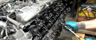
Check the tightness of the cylinder head mounting bolts at the end of the run-in and every 40 thousand km on a warm diesel engine in the following order:
— remove the cap and cylinder head cover;
— remove the rocker arm axle with rocker arms and struts;
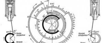
— using a torque wrench, check the tightness of all cylinder head mounting bolts in the sequence shown in Figure 1 and, if necessary, tighten them.
After checking the tightness of the cylinder head bolts, reinstall the rocker arm shaft and adjust the clearance between the valves and rocker arms.
Figure 1 — Diagram of the sequence of tightening the cylinder head bolts
Modifications
The procedure for adjusting the valves is identical for other modifications of the series. Among them is also D-245-06. The engine has a power rating of 105 horsepower, four cylinders and free atm. inlet. The model is installed on MTZ 100/102 tractors. The engine is equipped with a ST-142N starter, generator, as well as a compressor, gear-type pump, pump and clutch.
This installation has an in-line arrangement of cylinders and a turbine charging system. The motor is installed on MAZ-4370 vehicles and is equipped with a 24-volt starter, a compressor with a turbine, a water, oil and gear pump.
The clutch is single-disk. The modification has a power of 108 “horses” and an in-line arrangement of cylinders. Mounted on ZIL 130. The D-245 engine is equipped with a fuel pump and a pneumatic compressor. The timing kit includes fasteners, washers, nuts, pushers, camshafts, disc clamps. —
Checking the clearance between valves and rocker arms
Check the gaps between the valves and rocker arms and, if necessary, adjust every 20 thousand km, as well as after removing the cylinder head, tightening the cylinder head bolts and when valve knocking occurs.
When checking on an unheated diesel engine (water and oil temperature no more than 60°C), the gap between the rocker arm striker and the end of the valve stem should be:
1) intake valves - 0.25 mm;
2) exhaust valves - 0.45 mm.
When adjusting the gap between the end of the valve stem and the rocker arm on a cold diesel engine, set:
exhaust valves - 0.45 mm.
Figure 2 - Adjusting valve clearance.
Make adjustments in the following sequence:
— remove the cylinder head cover cap and check the fastening of the rocker arm axle struts;
- turn the crankshaft until the valves in the first cylinder overlap (the intake valve of the first cylinder begins to open, and the exhaust valve begins to close) and adjust the clearances in the fourth, sixth, seventh and eighth valves (counting from the fan), then turn the crankshaft one revolution, installing overlap in the fourth cylinder, and adjust the clearances in the first, second, third and fifth valves.
To adjust the gap, loosen the lock nut of the screw on the rocker arm of the adjustable valve in accordance with Figure 2 and, turning the screw, set the required gap using the feeler gauge between the rocker arm striker and the end of the valve stem.
After setting the gap, tighten the lock nut. After adjusting the valve clearance, replace the cylinder head cover cap.
Source
Spare parts for trucks
Full model range: GAZ-3307, 53, GAZ-3309, GAZ-66, 3308, 33081, 33086, GAZ-33104
Car clutch GAZ-3309, GAZ-3308, GAZ-33081 Sadko for diesel engine
The clutch of the GAZ-3309, GAZ-3308, GAZ-33081 Sadko (diesel engine D-245) is permanently closed, single-disk, dry, with a central pressure diaphragm spring and a damper device on the driven disk. Pressure disk 19 (Fig. 1) is connected to casing 10 by three groups of plates.
The clutch and release mechanism of the GAZ-3309, GAZ-3308, GAZ-33081 Sadko are located in the clutch housing 21, which is attached to the rear sheet of the engine with ten nuts 16 studs and a bolt, under which conical spring washers 15 are installed with the convex side to the nuts and the bolt head.
Centering the clutch housing relative to the axis of the engine crankshaft is carried out using two pins 20 pressed into the clutch housing. On the clutch housing there are 6 brackets for the rear engine mounts, which are secured with 5 bolts.
Rice. 1. Clutch GAZ-3309, GAZ-3308, GAZ-33081 Sadko (diesel engine D-245)
1 flywheel; 2, 5 - bolts; 3 - fork; 4 — rear cushion; 6 — rear engine mount bracket; 7 — protective ring; 8 — clutch; 9 — rivet of the friction lining; 10 - casing; 11 — support ring; 12, 20 — pins; 13 - bearing; 14 — gearbox input shaft; 15 — washer; 16 - nut; 17 — driven disk; 18 — disc pressure spring; 19 — pressure disk; 21 — clutch housing
There is no gap between the pressure spring 18 and the clutch bearing 8, so the inner ring of the bearing rotates at the engine crankshaft speed. During operation, the clutch does not require adjustments.
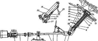
The clutch control drive for GAZ-3309, GAZ-3308, GAZ-33081 Sadko is hydraulic. The clutch master cylinder 15 (Fig. 2), mounted on the front panel of the cab, is actuated by the suspended pedal 20.
The master cylinder of the GAZ-3309, GAZ-3308, GAZ-33081 Sadko clutch is connected by a hose 2 to one of the sections of the three-section supply tank 1, equipped with an alarm sensor for an emergency drop in the brake fluid level (the other two sections of the tank supply the hydraulic drive of the dual-circuit service brake system).
Tightening diagram of the engine block head d 245
Checking the tightness of the cylinder head bolts
Check the tightness of the cylinder head mounting bolts at the end of the run-in and every 40 thousand km on a warm diesel engine in the following order:
— remove the cap and cylinder head cover;
— remove the rocker arm axle with rocker arms and struts;
— using a torque wrench, check the tightness of all cylinder head mounting bolts in the sequence shown in Figure 1 and, if necessary, tighten them.
After checking the tightness of the cylinder head bolts, reinstall the rocker arm shaft and adjust the clearance between the valves and rocker arms.
Figure 1 — Diagram of the sequence of tightening the cylinder head bolts
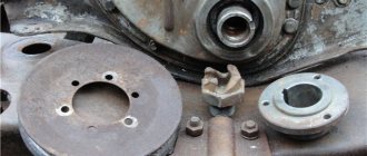
Preparing the tightening surface of the block and head
The head is installed in its original place after partial or major repair of the engine units and components. Before installing the head, new liners are installed in the block, which are sealed with special rubber rings that prevent coolant from leaking out of the jacket. The installed sleeve protrudes with its upper edge above the plane of the block. Pistons and liners are selected according to one size group, and the connecting rods and pistons are additionally weighed. The permissible difference in weight should not exceed 30 g.
Preparation of the contracted surface of the block and head.
To connect the connecting rod and piston, the pin is pressed into the piston using a special mandrel, and then secured against longitudinal movement with locking rings. A correctly selected finger does not move in the mounting sockets under the influence of its own weight.
The skew of the pin in the hole of the connecting rod bearing, as well as bending or conical wear of the cylindrical element is not allowed.
Rings are installed in the grooves on the piston body to provide compression and remove traces of oil from the surface of the liner. MTZ naturally aspirated engines use 3 compression rings, supercharged engines are equipped with 2 rings, the top one is coated with a wear-resistant chromium-based alloy. The ring locks are placed at 180° intervals, providing increased compression. When installing parts, you need to pay attention to the marks indicating the correct location of the rings relative to the piston bottom.
Before installing the pistons, it is necessary to install the crankshaft in its original place (if it was dismantled for grinding from the replacement). Then a piston with a connecting rod is installed in the cylinder liner, after which the liners are mounted and the caps of the main and connecting rod bearings are tightened. To check the correct assembly, use a torque wrench to turn the engine shaft.
The standard force should not exceed 60 N/m; if there is increased resistance to rotation, it is necessary to find the cause of the malfunction.
Installing the gasket and cylinder head on the block
The gasket is placed on the upper surface of the block, previously wiped with a clean rag. It is first recommended to check the condition of the aligned planes of the block and head with a metal tool ruler. Warping of parts is not allowed, since curved surfaces do not provide uniform clamping of the gasket, which will be pierced by the flow of exhaust gases. Damaged planes are ground on a special machine, and a metallized gasket with an increased thickness of material is used to seal the joint.
Installing the gasket and cylinder head on the block.
Before installing the gasket, it is recommended to re-check the protrusion of the upper flange of the cylinder liners. On an atmospheric diesel engine, the permissible value is in the range of 0.065-0.165 mm, on a supercharged version - 0.05-0.11 mm. To ensure uniform installation of the liners after replacement, it is necessary to install the head housing on the block, which is pressed with standard bots. Metal spacer sleeves 100-105 mm long are placed under the heads of the fastening elements; the tightening torque does not exceed 10-15 N/m.
When connecting parts, a new gasket is used; using a previously used plate is strictly prohibited. The part is removed from the plastic bag; it is recommended to inspect the surface of the part and make sure there are no tears or dents. To improve the tightness and facilitate the removal of parts during future repairs, apply graphite heat-resistant paste to both sides of the gasket.
Then the cylinder head is placed on top of the gasket, bolts are inserted into the holes, which are then tightened with a torque wrench. To ensure the quality of the connection, it is necessary to use new bolts, since old parts are deformed during tightening and during diesel operation. A thin layer of engine oil is applied to the threaded part, and the bolts are screwed into the holes by hand.
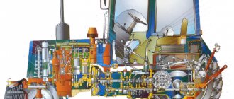
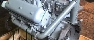
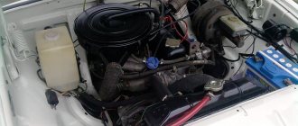
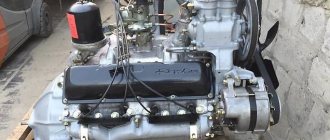
Engine D-245
In order to ensure a better level of acceleration, a turbine compressor is used with the ability to adjust the air flow. This ensures an increased level of torque even at a minimum number of crankshaft revolutions. At the same time, such an engine with a turbine exhausts exhaust gases that comply with European standards Euro 3. But the entire series of such engines is intended for use only in ambient temperatures ranging from -45 to +45 degrees. The main place of use of these units is their installation in road, construction, and wheeled equipment.
Motor characteristics. general information
The use of an internal turbine compressor with adjustable air flow makes it possible to create optimal throttle response when the engine is running. This indicator is ensured by an enhanced torque parameter even at minimum shaft speed. Also, the exhaust gases meet all required standards. —
All motors in the series are designed to work at tempo. conditions up to +40 degrees Celsius. The main area of application of these diesel engines is power plants for construction equipment, road equipment and wheeled tractors.