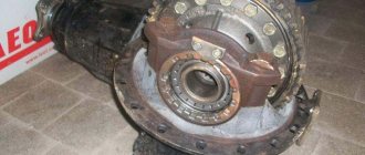
REMOVAL AND DISASSEMBLY OF THE REAR AXLE
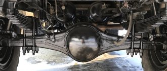
To disconnect the rear axle, the vehicle must be placed on a flat horizontal platform or on an inspection ditch equipped with a lifting device. Using a lifting mechanism, lift the rear of the car so that the rear springs are freed from the load. Disconnect the ends of the rear suspension springs from the frame brackets and lift the frame, first placing supports or a special jack under the axle gearbox (Fig. 5-3). Disconnect the propeller shaft from the rear axle drive gear flange. Disconnect the brake hoses. Roll the rear axle out from under the frame, supporting it by the gearbox. Lower the frame onto the stands.
Dismantling the rear axle with two-stage final drive
Remove wheels, springs and brake chambers. Drain the oil, remove dirt, wash the bridge with a degreasing solution and blow off with compressed air.
Disassembly of the rear axle should be done on a special stand model 689-00 (Fig. 5-4). If there is no stand, disassembly can be done by installing the bridge on stands. 1 To remove axle shafts and wheel hubs, unscrew the nuts securing the axle shaft to the hub and remove the spring washers. Screw two M12x1‚75 bolts into the holes of the flange (Fig. 5-5), move it from place, and then manually remove the axle shaft flange gaskets. Using the same method, remove the other axle shaft from the rear axle housing. In Fig. Figure 5-6 shows the removal of the rear wheel hubs using a puller. And to do this, you need to turn the power screw 2 to its original position, install the flange of the ring grip 1 on the wheel studs and secure it with wheel nuts.
Disconnecting the rear axle from the frame
Then install the power screw stop at the end of the axle housing and rotate the power screw with handle 3 of power screw 2 clockwise until the wheel hub is completely removed.
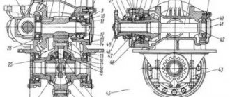
To remove the main gear, you need to turn the rear axle so that the main gear is positioned vertically upward. Unscrew the bolts and nuts of the studs securing the gearbox housing to the rear axle housing.
Install a bracket on the flange of the main gear reducer (Fig. 5-7) and use a lift to remove the main gear from the rear axle housing. Disassembly of the main gear and differential is carried out on a stand or bench in the following order.
Disassembling the ZIL gearbox
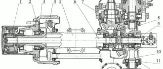
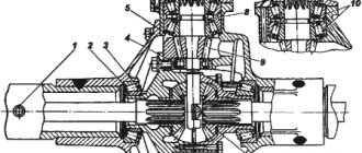
To remove and disassemble the drive bevel gear assembly, unscrew bolts 23 (Fig. 5-8) and, lightly tapping the bearing cup with a hammer, remove it together with the drive
with gear 24. Remove adjusting shims 11.
To disassemble and install the cup 4 (Fig. 5-9) of the bearings assembled with the drive bevel gear in fixture 2 and secure it with clamps 3 and clamp 1, which will keep the gear from rotating.
Unscrew and unscrew nut 17 (see Fig. 5-8) securing the flange, remove the nut support washer and flange 18, tapping it with a hammer. Unscrew the bolts 15 securing the cover 19, remove the cover with the gasket and the thrust washer 20. If the cuff 16 is faulty, press it out of the cover.
To press out the drive bevel gear shaft, install the bearing cup with the shaft on the press pads and press out the shaft (Fig. 5-10). If there is no press, the same operation can be performed by striking the end of the drive gear shaft against a wooden spacer.
Removing the gearbox from the crankcase
Remove the drive bevel gear 24 from the crankcase (see Fig. 5-8) together with the inner ring of the bearing 12, adjusting washers 22 and spacer sleeve 13. Remove the front bearing from the glass, press the outer ring of the front bearing out of the crankcase using a mandrel model 80423.00 ( Fig.5-11). In the same way, but using a different mandrel, press out the outer ring of the rear bearing.
It is recommended to remove the rear bearing from the drive gear shaft using a puller 20P-7984 (Fig. 5-12) or a puller model I 80330.000.
gearbox ZIL-130
To remove and disassemble the differential, you need to bend the locking plates from the heads of bolts 2 (see Fig. 5-8) and unscrew the bolts securing the stopper 3 on both sides, remove the locking plates and stoppers of the adjusting nuts.
Devices
Unscrew the bolts securing the covers 29 of the differential cup bearings, unscrew these nuts with an angled socket wrench, mark the covers and remove them, mark and remove both adjusting nuts 4, remove the differential along with the bearings.
To disassemble, place the differential in a vice, holding it by the rim of the driven spur gear. Unscrew the nuts of the bolts securing the differential cups and the driven spur gear. Mark with a core the relative position of the differential cups (processing of the sockets for the differential crosspiece in the satellite cups is done as an assembly, and during disassembly it is necessary to keep the cups together without depersonalizing them).
Bearing removal
Remove the right cup and the right axle gear 32 with the support washer 31, remove the cross with the satellites and the satellite support washers, and then remove the left axle gear with the support washer,
Remove the driven spur gear from the left differential cup 5 using a copper mandrel and a hammer.
In this case, the puller I 80331.00. is installed so that the grips 5 pullers fit into the end of the inner ring of the bearing. To remove and disassemble the drive cylindrical gear, you need to unscrew the bolts 26 securing the bearing covers 9 and 27 with a spanner wrench and remove them together with shims 10 and the outer rings of the bearings.
A pack of shims on one side should not be mixed with a pack of shims on the other side; it is recommended that they be secured to their covers using thin wire. Remove the drive cylindrical gear 8 from the gearbox housing. To remove the right and left bearings, it is recommended to use a TsKB-2502 puller. The method of pressing the bearings is shown in Fig. 5-14
Pullers
Methods for pressing out the outer rings of bearings using a puller model 2480 are shown in Fig. 5-15. In Fig. 8-16 shows a puller model I 803.33.000.
If there are cracks or holes }: in the gearbox housing and bearing caps, damaged parts should be replaced. Welding of non-through cracks is allowed. Damage to the thread is allowed no more than two threads.
The permissible runout of the axle shaft, measured at a distance of 80 mm from the flange, is allowed no more than 1.0 mm.
The permissible runout of the axle shaft flange should not exceed 0.2 mm.
If there are breaks, signs of twisting, bending or cracks on the axle shafts, they should be replaced.
WATCH THE VIDEO
Principle of operation
It should be noted that power supply with a gas mixture, the design of the entire gas cylinder system of previous generations is much simpler than the design of a gasoline fuel mixture supply system.
Converting a vehicle to operate on gas equipment and its corresponding conversion looks like this. First, in the luggage compartment, cargo compartment, under the bottom of the car, on the frame, a special container is installed, intended for filling with gas. In the engine compartment (underhood space) an evaporator reducer, additional devices whose functions are related to the supply of a gas mixture to the engine, and fuel adjustment mechanisms are installed.
The cylinders are filled with a liquid mixture of propane and butane. If the pressure corresponds to atmospheric pressure, the fuel is in a gaseous state. If the pressure is higher than atmospheric pressure, the gas is converted into liquid fuel, which can evaporate at household temperatures. Therefore, only sealed containers are used for liquefied gas. The pressure in them can be 2-16 atmospheres.
Rear axle assembly with two-stage final drive
Before assembling the main gear and differential parts, wash them in a degreasing solution, blow them with compressed air, and check for compliance with their technical requirements.
It is recommended to lubricate the parting planes and sealing gaskets with UN 25 paste.
Lubricate the bearings with Litol-24 or press grease.
To assemble the drive bevel gear shaft into the housing 21 (see Fig. 5-8) of the drive bevel gear bearings, press the outer ring of the front bearing 14 until it stops into the crankcase shoulder using a mandrel (NATsh`0.009...0.059 mm). Rotate the crankcase and press in the outer ring of the rear shaft bearing 12 (preference 0.010...0.068 mm).
Place the inner ring of the rear bearing 12 onto the shaft of the drive bevel gear 24, pressing it until it stops, the spacer sleeve 13, the adjusting washers 22, the cup of bearings 21 into the front bearing 14. Install the assembled shaft of the drive bevel gear with a stand under the press and press both bearings until it stops. . The bearing fit should be: for the rear bearing with an interference fit of 0.003...0‚038 mm, for the front bearing a fit from a gap of 0.015 mm to an interference fit of 0.016 mm.
Install thrust washer 20. Close the drive gear housing with cover 19 with gasket, having previously pressed cuff 16 into the cover.
Install flange 18 with reflectors onto the shaft splines and press it on. Put on the nut washer 17 and secure the flange 18 with a nut (the cover is secured with bolts, and the nut is cottered only after adjusting the preload of the bearings).
Gearbox with two-stage transmission
Adjusting the drive bevel gear shaft bearings.
To determine the need to adjust the bearings, you should: tighten the nut |7 of the flange until it stops, check whether the drive gear shaft rotates freely by hand. If, after checking, axial play of the shaft is felt or the shaft rotates tightly, the bearings should be adjusted.
Adjustment of the bearing preload is carried out by selecting two adjusting washers 22 from the factory-produced washers of the following sizes: 2.00...2.02; 2.05…2‚07; 2.15…2.17; 2.35…2‚37; 2.45…2.47; 2.55…2‚57; 2.60…2.62 mm. The tightening torque of the flange mounting nut is 200…250 N.m (20…25 kg cm).
pressing of bearings
When tightening the nut, it is necessary to rotate the drive gear shaft so that the bearing rollers are in the correct position between the conical surfaces of the bearing rings.
Checking the tightness of the bevel gear bearing assembly is shown in Figure 5-17. The torque required to rotate the drive gear shaft in oil-lubricated bearings should be 10…35 N.m (0.1…0.35 kg cm). If less or more torque is required to rotate the drive gear shaft, you must disassemble the drive gear again and replace the adjusting washers 22 (see Fig. 5-8), reassemble the drive gear in the bearing housing and check again.
When checking the rotation of the drive gear shaft, the bearing cover 19 must be moved towards the flange so that the centering protrusion of the cover comes out of the bearing housing 21 and so that the cuff 16 does not provide resistance to the rotation of the shaft.
After the final adjustment of the bearings, it is necessary to secure the cover 19 with bolts 15 with spring washers and the nut 17 of the flange 18. The nut securing the drive gear flange must be tightened to capacity and cottered.
Assembling the drive spur gear shaft.
If the driven bevel gear 25 was removed from the shaft of the drive cylindrical gear to replace the rivets, then you must first install it and rivet it with rivets, then press the bearings onto the shaft journals.
It is recommended to heat the driven bevel gear to a temperature of 120...160 °C before installation, and then install it on the shaft flange, aligning the holes of the gear and flange. After cooling of the driven bevel gear, its fit should correspond to a tightness of 0.036...0.1 15 mm. When replacing a driven bevel gear, the drive bevel gear paired with it must also be replaced.
Place the shaft of the drive cylindrical gear 3 (Fig. 5-18) vertically on the stand 1, press on the bearing ring 2. Install the bearing ring 5 on the shaft journal and, using a mandrel 6, press both bearings under a press until they stop against the shaft shoulder. The bearings should be seated on the shaft journals with an interference fit of 0.003 to: 0.038 mm.
Pressing in the outer ring
Assembling the bearing caps for the drive spur gear shaft. Install the right cover onto the stand | (Fig. 5-19) and press the outer ring of bearing 3 into the seat of the cover 2. Perform the same operations for the left cover, using a reference of a smaller diameter. The rings are seated with an interference fit of 0.009…0.059 mm.
Differential assembly.
The differential gears should be lubricated with oil during assembly. Install the right cup 1 (Fig. 5-20) of the differential on the plate, place bearing 2 on the chamfer of the cup neck and press it in using mandrel 3 (bearing tension 0.020...0.055 mm). The sequence of operations for assembling the left differential cup is the same as for the right one.
Pressing on the bearing
Place the left differential cup on a stand with a hole in which the journal with bearing 14 should be placed (Fig. 5-21). Place the driven spur gear on the cup, lightly tapping it with a copper hammer, place the support washer and the left axle shaft gear in the cup.
Place four satellites with supporting spherical washers onto the crosspiece tires. The gap between the satellite hole and the crosspiece tenon is 0.03...0‚105 mm. Place the spider assembly with pinion gears on the differential cup, place the right axle shaft gear with the support washer on the satellites, install the right differential cup, aligning the cups according to the marks made with a core during disassembly, insert the bolts into the holes of the satellite cups and the driven spur gear, screw the nuts onto the bolts by hand.
Remove the differential from the stand and place it in a vice. Fasten the nuts by clamping the driven gear in a bench vice. The tightening torque of the nuts is 120.440 N.m (12...14 kts.m). The engagement of the differential gears and their rotation in the assembled differential must be free when turned by hand. The gap between the end of the gear axle shafts and the support washer should be no more than 1.2 mm for each side. The gap is checked through the control holes located on the differential cups (see Fig. 5-21).
Assembly and adjustment of the gearbox.
During assembly, the bearings in the drive spur gear are adjusted, the gearing of the bevel gear teeth is adjusted, and the differential bearings are adjusted.
Differential assembly
Install the shaft of the drive cylindrical gear 25 and the inner rings of the bearings into the gearbox housing 7. Place a set of adjusting shims on the flanges of covers 9 and 27. Place the covers in place as an assembly with the outer rings of the bearings pressed into them, and secure the covers with bolts 26. Check the preload of the bearings. The set of adjusting shims produced by the factory consists of five pieces with dimensions 1.0; 0.5; 0.2; 0.1; and 0.05 mm.
Bearing tightening
Gaskets with a thickness of 0.05 and 0.1 mm, one piece at a time, must be installed under each main gear housing cover, the rest - as needed.
After adjusting the bearings, the torque required to rotate the shaft in the bearings should be |...3.5 N.m (0.1...0.35 kg cm), which is checked with a dynamometer (Fig. 5-23).
Having finished adjusting the bearings, install the drive bevel gear assembly on the final drive housing and secure with bolts.
Adjusting the mesh of bevel gear teeth.
When installing the drive bevel gear assembly, it is necessary to check the engagement of the teeth of the drive and driven bevel gears (paint along the contact patch) and, if necessary, adjust the engagement and set the required gap between the teeth.
The position of the contact patch on the teeth of the new gears with adjusted gear engagement should correspond to the contact patch shown in Fig. 5-24, a, and under load and in Fig. 5-24‚b. In this case, the gap between the teeth must be maintained within 0.15...0.4 mm for new gears and 0.5 mm (no more) for used ones.
Contact patch position
The set of adjusting shims produced by the factory consists of five pieces with dimensions 1.0; 0.5; 0.2; 0.1 and 0.05 mm. The driven bevel gear is moved by moving the gaskets (see Fig. 5-22) from under the flanges of one gear housing cover to the flange of the other cover without changing their overall thickness, so as not to disturb the adjustment of the drive spur gear shaft bearings.
Checking gear engagement
After final adjustment of the position of the drive and driven bevel gears, the torque required to rotate the shaft of the drive cylindrical gear in the bearings should remain unchanged within 1...3.5 N.m (0.1...0‚35 kg cm) (see Fig. .5-23).
After completing the adjustment of the drive and driven bevel gears, it is necessary to finally tighten the bolts securing the bearing caps of the drive cylindrical gear and the bolts securing the housing of the drive bevel gear. The tightening torque should be 60...80 N.m (6...8 kg cm).
The gap between the teeth is measured with an indicator (Fig. 5-25) at the wide part of the tooth for at least three teeth of the driven gear, evenly spaced around the circumference.
For normal installation of gear teeth meshing along the contact patch, it is necessary to apply a thin layer of oil paint to the working surfaces of several teeth of the driven bevel gear. Then “turn the drive bevel gear shaft one way and the other, braking the driven gear with your hand.
Based on the formed contact spots, the nature of the gear engagement is determined. The correct installation of gear mesh is shown in Fig. 5-24. If the position of the spot is incorrect, normal engagement should be achieved by moving the driving and driven gears in the axial direction (Table 5-2).
The movement of the drive bevel gear is carried out by changing the thickness of the set of shims (Fig. 5-26) installed between the flanges of the drive gear housing and the gearbox housing.
Shims
Contact patch table
GBO reducers
This material talks about the evolution of automobile gas reducers produced by the Lovato company, but most of the following is also true for other brands represented on the Russian market.
Purpose of the gas reducer
The first task of any automotive propane reducer, regardless of the generation of gas equipment, is to transfer gas from a liquid to a gaseous state and maintain a stable gas temperature during engine operation.
The second task is to ensure gas pressure at the outlet of the reducer, in accordance with the current fuel demand of the car engine. The tasks, in general, are simple, but very important for the proper operation of the entire gas system of any generation of gas equipment.
- It is important to connect to the engine cooling system so that the circulation of coolant through the gearbox is effective in all operating modes of the internal combustion engine, and at the same time, this connection should not affect the operation of the heater or other vehicle devices. Simply put, the gas reducer should not cool down during operation, and all devices that worked in the car before and after the installation of gas equipment should work without changes.
- The maximum power of the Lovato gearbox must match or exceed the engine power (in the case of 1st and 2nd generation systems, installing a gearbox larger than the required power is not recommended). This is important not only for efficient gas evaporation, but also for the ability of the reducer to maintain a stable differential pressure, which is extremely important for Lovato 4th generation LPG systems.
If the vehicle is equipped with a gearbox of less power than the required power, this will not allow the Lovato gas system to operate normally and safely under high engine load conditions (there may be interruptions in operation, expressed in jerks, or a noticeable loss of power compared to gasoline, and In some cases, during sudden acceleration, a gas smell may appear).
HBO repair
Repair of gas cylinder equipment is required when malfunctions are discovered that have arisen due to poor quality of spare parts or improper installation. And also in the case when the equipment has expired and needs to be replaced.
Our experienced installers eliminate faults of any complexity and work with gas fuel systems of 1–4 generations. They know the specifics of installing equipment on any car model: cars and trucks. They easily correct the mistakes of previous installers, preventing the recurrence of breakdowns.
In the event of an irreparable situation, when adjustment is impossible, we will completely replace the gas system. Our company organizes supplies of equipment directly from manufacturers and sells them at competitive prices with a guarantee.
The sensitivity of the LPG reducer is not adjustable
First, unscrew the sensitivity screw completely and pull it out, there should be a spring there (I’ve seen that it’s stupidly missing), then screw it all the way until it stops turning, screw the XX screw all the way as well. when the engine is turned off, give 12V to the gas solenoid valve and on the gearbox, by the way, it is electronic or vacuum (then a vacuum must be connected) then for the electronic gearbox: when you connect 12V, you should hear a click of the valves, the gearbox itself should not hiss (the gas should not start when fully closed. screw.sensitivity) turn the sensitivity screw a little until it starts to hiss slightly, then start it up and use the choke to maintain the speed (necessarily on a warm engine.) unscrew the XX screw and remove the choke, then further adjust as per the manual, this method helped me.