Checking and adjusting the installation angle of fuel injection advance for diesel engine D-260.1
If it is difficult to start a diesel engine, there is a smoky exhaust, as well as when replacing and installing a fuel pump after adjustment on a stand or repair, be sure to check the setting angle of the fuel injection advance on the diesel engine.
Check the angle in the following sequence:
a) for high pressure fuel pumps mod.363.1111005-40
- set the piston of the first cylinder on the compression stroke 30 - 40° to the position of the required installation angle of injection advance on the scale on the damper body;
- set the stop lever and the regulator control lever to the position corresponding to the maximum fuel supply;
- disconnect the high-pressure tube from the fitting of the first section of the pump and instead connect a control device, which is a piece of high-pressure tube 50...70 mm long with a pressure nut at one end and the other end bent to the side by 90° (Figure 25);
Figure 25 — Sketch of the control device
1 - pressure nut; 2 - high pressure pipe
- fill the fuel pump with fuel, remove air from the low-pressure system and create excess pressure with a manual priming pump until a continuous stream of fuel appears from the control device tube;
- Slowly rotating the diesel crankshaft clockwise and maintaining excess pressure in the pump head (boost pump), watch for fuel flowing out of the control device. When the fuel stops flowing out (up to 1 drop is allowed in 10 seconds), stop rotating the crankshaft;
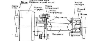
- Determine the position of the graduated scale on the damper body 2 relative to the alignment pin 3 secured to the distribution cover 1 (Figure 26).
Figure 26 — Setting the fuel injection advance angle.
1 — distribution cover (manhole cover removed); 2 — silicone damper; 3—locating pin; 4 - pulley
If the pin is in the range of divisions “19…21” on the graduated scale, then the fuel supply start angle is set correctly, i.e. the piston of the first cylinder is set to a position corresponding to 19…21° before TDC.
If the pin is not within the specified range, make an adjustment by doing the following:
- Rotating the crankshaft, align the “20” mark on the graduated scale of the damper housing with the alignment pin;
- remove hatch cover 1 (Figure 4);
- loosen the nuts securing the fuel pump drive gear to the drive coupling by 1...1.5 turns;
- Using a wrench, turn the fuel pump shaft counterclockwise by the nut until the pins stop against the edge of the groove of the fuel pump drive gear;
- create excess pressure in the fuel pump head until a continuous stream of fuel appears from the control device tube;
- by turning the pump shaft clockwise and maintaining excess pressure, watch for fuel flowing out of the control device;
- When the fuel stops flowing out, stop rotating the shaft and fix it by tightening the nuts securing the drive gear to the drive coupling half.
Recheck the timing of the start of fuel supply.
Disconnect the control device and reinstall the high pressure pipe and manhole cover.
b) for high pressure fuel pumps PP6M10P1f-3491; PP6M10P1f-3492
- set the regulator control levers to the position corresponding to the maximum fuel supply;
- disconnect the high-pressure tube from the fitting of the first section of the pump and instead connect a momentoscope (a union nut with a short tube, to which a glass tube with an internal diameter of 1.2 mm is connected using a rubber tube);
- turn the diesel crankshaft clockwise with a wrench until fuel without air bubbles appears from the glass tube of the momentoscope;
- remove some of the fuel from the glass tube by shaking it;
- turn the crankshaft in the opposite direction (counterclockwise) 30 - 40°;
- slowly rotating the diesel crankshaft clockwise, monitor the fuel level in the tube; when the fuel begins to rise, stop rotating the crankshaft;
- determine the position of the index pin 3 fixed on the distribution cover 1 (Figure 26).
If it is in the range of divisions “21…23” on the graduated scale marked on the body of the torsional vibration damper, then the setting angle of fuel injection advance is set correctly, i.e. the piston of the first cylinder is set to a position corresponding to 21…23° BTDC.
If the pointer is not within the specified ranges, make an adjustment by doing the following:
- Rotating the crankshaft, align the locating pin indicator with division “22” on the graduated scale of the damper housing;
- remove hatch cover 1 (Figure 5);
- loosen by 1…1.5 turns the three M10 nuts securing the fuel pump drive gear to the drive coupling half;
- remove some of the fuel from the glass tube of the momentoscope, if it contains it;
- using a wrench, turn the fuel pump shaft by the nut in one direction or the other within the grooves located on the end surface of the fuel pump drive gear until the glass tube of the momentoscope is filled with fuel;
- install the fuel pump shaft to its extreme (counterclockwise) position within the grooves;
- remove some of the fuel from the glass tube;
- slowly turn the fuel pump shaft clockwise until the fuel begins to rise in the glass tube; at the moment the fuel begins to rise in the glass tube, stop rotating the shaft and tighten the nuts securing the drive gear to the drive coupling half;
- re-check the moment the fuel supply starts;
- disconnect the momentoscope and reinstall the high-pressure pipe and manhole cover.
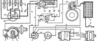
How to set the ignition timing with your own hands
Setting the ignition correctly means that you need to find the desired ignition timing (IAF). The tuning is done at idle, although this is understandable, but suddenly someone decided to put the car on a jack and tune it at speed.
To adjust the ignition, you need to know that the optimal good engine crankshaft speed at idle is from 850 to 900 rpm. The ignition timing angle should be between -1 and +1 degrees. This is a degree relative to top dead center (TDC).
A popular device used to set the ignition is a strobe light. With a strobe, the settings are more precise. But, if it is not there, then set it up using a control light.
If a light bulb is used for adjustment, it is connected to the positive terminal on the ignition distributor (distributor), and the light bulb base is connected to ground. Let's look at the configuration options separately.
Now we have begun to disassemble the power units of automobiles. Please write in the comments what kind of car you have and with what engine. Later, materials on such engines will be published with useful information, for example, if the timing belt breaks, whether the valves are bent, also technical characteristics, design, on which cars such engines are installed, etc. We have already reviewed the ZC engines from the Honda plant, 3UZ-FE, 3S-FE, 1AZ-FE.
Strobe setting
- Start the engine, heat it to operating temperature and turn it off.
- Connect the strobe light to the car's network.
- Unscrew the nut securing the distributor cap - ignition breaker.
- Place the alarm sensor on the high-voltage wire of the first cylinder.
- If there is a vacuum corrector hose on the distributor, then it must be disconnected and plugged.
- Direct the strobe light onto the engine crankshaft pulley.
- Now start the engine and leave it idling.
- Now you need to turn the distributor body and fix it so that the mark on the crankshaft pulley coincides with the mark on the timing mechanism.
- If the marks match, tighten the nut.
Features of maintenance of MTZ-1221 tractors
The serviceability of MTZ special equipment and its performance directly depend on its technical condition. Therefore, it is important to provide machines with timely care, repair and elimination of minor problems, replacement of worn-out components with original MTZ-1221 spare parts. Analogues or fakes are not always able to fully satisfy the performance of the tractor. In addition, the use of branded parts eliminates doubts regarding the coincidence of components with the factory parameters of the equipment.
News
Replacement of fuel injection pump on MMZ D-260.4, D-260.4S, D-260.3 engines
The breakdown of any equipment is one of the unpleasant moments that stops the work process. The most expensive repair is engine maintenance. In order to avoid getting into a difficult and “expensive” situation, it is necessary to diagnose and repair failed parts in advance.
One of the common causes of unstable engine operation is the failure of the high pressure fuel pump.
In this article we will look at the injection pump 365.1111005-40.04 of the Compact 32 family, its analogues and the procedure for replacing it.
A high-pressure fuel pump is one of the important elements of the engine, responsible for supplying precisely measured portions of fuel to the cylinders at a certain pressure and at a certain point in the cycle, corresponding to a given load applied to the crankshaft.
Fuel injection pump 365.1111005-40.04 of the Compact 32 family is a high-pressure fuel pump with a vertical in-line arrangement of plunger pairs, the number of sections is 6, the intersectional distance is 32 mm. This high pressure fuel pump is used for diesel engines with a cylinder capacity of up to 1.5 liters and a power of up to 30 kW per cylinder. Fuel injection pump 365.1111005-40.04 allows for cyclic flow up to 160 mm and fuel injection pressure from 450 to 1100 ba. They are equipped with a mechanical all-mode and single-mode speed controller. The external speed characteristics of the engine are formed by a forward, reverse, and boost corrector.
Main characteristics of the tractor
In the line of special equipment of the Minsk plant, MTZ-1221 stands out for its manufacturability. This is a modern, powerful machine, designed to meet the requirements of efficiency and versatility.
Traction characteristics and the ability to increase high speed allow the tractor to be used in large-scale transport events, including local cargo transportation. You can also use trailed and mounted equipment of various types, and combine the MTZ-1221 with agricultural machines, loading and unloading equipment and excavator complexes.
These tractors are used in various fields: agriculture, urban agriculture as tractors and vehicles. In comparison with special equipment of other series from the plant’s line, this machine has increased ground clearance (up to 480 mm). The turning radius is about 5.4 m.
This tractor is characterized by reliability and endurance. Due to its practicality, it can be used when performing various types of work, including in difficult conditions (weather, road). However, the reliability of special equipment can be ensured only if it is in absolute technical condition. It is important to provide the MTZ-1221 with proper care and correct faults in a timely manner.
Related Posts
MTZ 1221, the voltage indicator is blinking, what is the problem?
MTZ 1221, the voltage indicator is blinking, what is the problem?
Is the new model MTZ 1221 injection pump drive gear suitable for the old version?
Is the new model MTZ 1221 injection pump drive gear suitable for the old version? Has anyone encountered this? Write in the comments
Why is there no charging on the MTZ 1221? The generator, fuse and converter are working. The batteries are working.
Hello, tell me the solution to the problem - there is no charging on the MTZ 1221. The generator is broken, the fuse and the converter are also working, the batteries are working. I removed the jumper block, after assembly it all started. Maybe there is some kind of diagram or in words, what’s what? Thank you.
Tractor MTZ 1221 Why, when you turn on the front axle, the pressure at idle drops to 4, and sometimes 2, and when you turn off the axle, it’s 9-10.
Good day. Tell me, tractor MTZ 1221 Why, when you turn on the front axle, the idle pressure drops to 4, and sometimes 2, and when you turn off the axle, it’s 9-10? The sensor is mechanical, the filters are clean.
On MTZ 1221 the brakes stick. Both sides jam. What to do?
Good morning, colleagues. On MTZ 1221 the brakes drank all the blood. Both sides jam. Maybe someone had this and did what.
Should the input shaft on MTZ 1221 go to the left, right, top to bottom, and not be rigidly attached?
Hi all. Tell me, on MTZ 1221 the input shaft goes left to right, top to bottom, in general, it is not rigidly attached. Should it be like this or not?
Mtz 1221 Why did the linkage and levers stop lifting? At high speeds it lifts itself, but the load is no longer there. I changed the pump, the valve on the distributor is clean.
Hello people This is the problem with MTZ 1221. The linkage and levers have stopped lifting. At high speeds it lifts itself, but the load is no longer there. I replaced the pump 3 times for 32 nsh. All to no avail, nothing helped. What could it be? The valve is clean on the distributor.
MTZ 1221. We removed the thermostat, the engine gets hot. Is it necessary to jam the small circle channel, and if so, how?
Good afternoon. I removed the thermostat at 1221. The engine is heating up, is it necessary to turn off the small circle channel, if so, how?
Is timber from Belarus 1221 suitable for Belarus 82.1?
Tell me, is the timber from Belarus 1221 suitable for Belarus 82.1?
Main features of maintenance
The main task of any maintenance is to maintain the serviceability and performance of special equipment. Maintenance is planned and preventive in nature and is performed with a certain regularity.
A 3-number maintenance system has been developed specifically for tractors. In addition to shift work, it includes 3 maintenance services (No. 1; 2; 3), which are periodic in nature. There is also seasonal maintenance of special equipment. This work is carried out at the beginning of the autumn-winter and spring-summer operational periods. Numbered work is carried out with the following frequency: No. 1 - after 60 engine hours; No. 2 - after 240; No. 3 - for production of 960 hours. During them, operations are carried out in accordance with the regulations, and any detected problems are eliminated.
Interesting: additional maintenance is also provided for equipment that is used in special conditions that differ sharply from standard conditions (in the desert, mountains, northern regions).
Features of daily maintenance
These works are carried out between working intervals (usually every 10 operating hours). Shift maintenance includes:
- checking for leakage of lubricant, fuel, water;
- adding technical fluids;
- measuring the oil remaining in the crankcase and replenishing the deficiency;
- draining the condensate formed in the pneumatic system receiver.
The radiator mesh is also inspected. During operation of special equipment in dry weather and increased levels of dust formation, it becomes clogged; it is important to clean it. It is also important to check the tires, heating of the diesel unit components, transmission, and hydraulic system.
Features of TO No. 1
Number maintenance is carried out after the ETO has been completed. Then they wash the car, check the oil, the tension of the belt on the fan in the engine, and the pressure in the tires. They also lubricate the bearings in the water pump and drain waste from the fuel system filter.
Numbered maintenance No. 1 is carried out after 60 operating hours. After 20 m/h, the condition of the oil contained in the sump is checked, the rotor is cleaned in a centrifugal filter, and lubricant is applied to the bearings in the drive axle driveshaft joints.
Carrying out maintenance No. 2
These operations are performed after 240 operating hours. Typically they include:
- Changing the oil in the crankcase.
- Draining of waste.
- Washing the air cleaner filters on the starting engine.
- Checking the transmission oil.
- Inspect the steering wheel and clutch pedals.
- Checking the fastening of the hubs on the rear wheels, side members, engine, gearbox housing.
Important: after 480 engine hours, another maintenance is carried out. This time, inspect the gap from the valve to the rocker arm, rinse the air cleaner thoroughly, and clean the central pipe in it.
Features of TO No. 3
This work is carried out after 960 operating hours. The order of operations first includes all measures from maintenance No. 2, after which a more in-depth inspection of special equipment is carried out, paying attention to all components and mechanisms, checking their degree of wear, serviceability and general condition.
After one maintenance No. 3 (after 1920 engine hours), another inspection is carried out. It pays attention to the condition of the relay contacts, commutators, starter brushes, inspects the pneumatic adapter and compressor on the pneumatic system, and applies lubricant to the flexible shaft in the tachospeedometer.
Important: when carrying out maintenance No. 3, not 1, but 2 repetitions are provided. After two similar events (after 3 thousand engine hours), the condition of the brushes on the starter and commutator is checked; hydraulic booster worm; The engine cooling system is flushed; The lubrication in the hubs on the front wheels is changed.
Answers to frequently asked questions
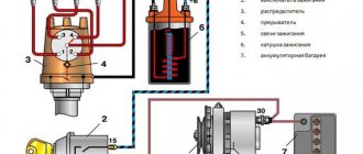
How can you tell if the starter relay is not working?
To determine whether the starter relay is working, apply power from the positive terminal of the battery directly to the control contact of the relay. After this, a click should sound; if it is faulty, there will be no sounds.
How to check whether the starter is working or not?
To check the serviceability of the starter itself, you need to apply current to it directly by connecting the power wires of the retractor relay (thick wire from the battery) and the electric motor (stud with a thick wire from the retractor to the starter). A working starter should start moving.
What to do if the starter does not work after turning the ignition key?
First, make sure there is voltage at the battery terminals. If you don’t have a tester, this can be done using a 12 V lamp. Then try to apply voltage directly to the starter: use a screwdriver to close the pin to which the wire from the battery goes and the control contact located nearby. If there is no reaction, check the quality of the contacts of the terminals on the battery, the ground contacts (with the body and the engine) and the contacts of the starter itself by cleaning and tightening the terminals. If the battery is discharged or the starter is faulty, you need to start the car with a pusher (manual transmission) or tow it to the repair site.
Setting the fuel injection timing on the D-240 MTZ 82 (80) engine
The often-called concept of “ignition adjustment” or “ignition installation” is unacceptable and technically illiterate in relation to the D-240 diesel engine of the MTZ-80(82) tractor, given that the fuel ignites under the influence of pressure at the end of the “compression” stroke in an atomized state. In relation to a diesel engine, this concept is called “fuel injection unit”. To operate a diesel engine and produce torque and power with the corresponding technical indicators, the fuel supply is synchronized with the operation of the piston group in the “compression” strokes in each individual cylinder with an appropriate repeating frequency. Correct adjustment ensures that fuel is injected into the cylinder at a certain moment - with a slight advance before the top dead center in the “compression” stroke of the working cycle.
Injection too early disrupts the thermal balance of air and ignitable atomized fuel, increasing ignition time. The result of late injection will be incomplete combustion of fuel, accompanied by engine overheating, smoke and loss of power.
Early or late ignition
Ignition of the mixture in the working chambers of the cylinders too early or too late causes poor performance of the internal combustion engine. The engine may not pull uphill, accelerate slowly, vibrate strongly, etc.
Signs of an incorrectly set ignition:
- the engine starts with difficulty;
- increased fuel consumption;
- the motor cannot develop power;
- in idle mode (idle speed), the internal combustion engine either stalls or over-gasses;
- the engine responds poorly to pressing the gas pedal;
- The internal combustion engine overheats;
- the engine detonates.
You can easily determine that the ignition needs to be adjusted if you hear popping sounds from the muffler and the car “sneezes.” It is recommended not to operate the machine in this mode, but to adjust it immediately. Moreover, one of the signs is detonation, which can destroy valves, pistons and cylinders.
Adjustment procedure
The need to install injection arises when replacing a high-pressure fuel pump (HPF) or installing it after repair, as well as after repairing the piston group of a diesel engine. The adjustment is carried out provided that the fuel equipment, injection pump and the adjusted gas distribution mechanism of the diesel engine are in good working order. The installation process consists of the sequential operations described below.
Installing the first cylinder on the compression stroke
On the right side, in the direction of travel of the machine, in the wall of the engine mounting to the clutch housing, above the longitudinal beam of the tractor frame near the oil filler neck, there is an installation dipstick. With its short threaded part it is screwed into the mounting wall and with its long threadless part it is installed outside. If it is necessary to install the first cylinder in the “compression” stroke position, the dipstick is installed in the hole, resting its long part against the engine flywheel. Slowly turning the diesel crankshaft, find a position in which the probe will fall into the hole on the flywheel and enter the body of the part completely by 4-5 cm. It is important not to confuse the installation hole with the technological, balancing drillings of the flywheel, which are much smaller in depth. The found position corresponds to an advance of 26 ̊ before the piston of the first or fourth cylinder approaches TDC. This position corresponds to the technical requirements of D 240 for setting the start of fuel injection into the cylinder during the “compression” stroke. To determine which of the cylinders in the first or fourth the “compression” stroke has begun, you need to remove the valve cover. A pair of closed valves will indicate in which of the two cylinders (first or fourth) the “compression” stroke has begun.
Why is early ignition installed?
Setting the ignition angle advance is necessary so that the fuel ignites before the piston reaches TDC (top dead center). The piston approaches TDC 10-27 degrees from the crankshaft revolution. Fuel injection occurs. When the air in the cylinder is compressed, the temperature rises to 350-900 degrees Celsius. This temperature is sufficient for diesel fuel to ignite spontaneously. When TDC is reached, the already burning mixture of fuel and air is compressed as much as possible by the piston. As a result of combustion, the resulting gases expand. They begin to press on the piston. The maximum pressure of expanding gases is achieved by compressing already burning fuel. Some engine designs provide for the supply of burning fuel to the combustion chamber. This further increases engine power.
The engines installed on MTZ tractors have different ignition timing angles. It is not necessary to know them. Because the design provides for setting the ignition timing. Depending on the location of the installation pulley. Which is located on the back of the engine. It is enough to turn it inside out and put it the other way around.
In this case, you need to get into the hole provided for it in the flywheel. After the dipstick is installed, the piston will be at the required advance angle before TDC. All that remains is to set the injection pump correctly. At the beginning of fuel injection by the plunger of the first cylinder.
Checking the injection advance angle
After starting, check the operation of the engine in different modes. In case of unstable or hard operation at high speeds, knocking and detonation, black smoke and incomplete combustion of fuel, the injection timing is checked and adjusted. Install the momentoscope on the first section of the pump and monitor the coincidence of the moments when the probe enters the hole in the flywheel and the start of fuel supply to the pump section. The moment of supply before the probe coincides indicates a large advance angle, but if the fuel supply does not start when the probe hits, the injection is late. If the injection timing does not match, correction is made by turning the injection pump shaft. Also open the pump cover, unscrew the two bolts securing the adjusting washer with the bar. To increase the advance angle, turn the shaft clockwise, and in the opposite direction, reduce the injection advance angle. Moving the shaft position by one adjustment hole on the washer corresponds to 3 turns of the diesel crankshaft. By turning the injection pump shaft in the desired direction until the holes on the washer and the gear flange coincide, the injection angle is changed. Assembly is carried out in the same order - install the washer with bolts on the bar in the matching holes.
Other methods of setting the ignition
Method by ear
Some people set the ignition by ear. Rotate the distributor and determine how the engine operates. This method is the simplest:
- Start the engine.
- Loosen the distributor nut.
- Rotate the distributor and determine for yourself how the internal combustion engine works. The engine should operate smoothly in the found position, without vibration. At the same time, the engine should develop the highest idle speed.
- After this position has been found, you now need to turn the distributor a couple of degrees clockwise and secure it with a nut.
Spark method
Another tuning method is using a spark. To do this, you need to align the marks on the crankshaft pulley with the timing mark. The slider mark points to the first cylinder. After this, you need to loosen the distributor nut and pull out the central high-voltage wire from the distributor cover.
Afterwards, bring this wire closer to ground so that there is 5 mm between them, and turn on the ignition. Rotate the distributor body 20 degrees clockwise. 20 degrees is 1-1.5 cm. Now you should slowly turn the distributor counterclockwise until a spark appears between the disconnected distributor wire and ground. In whatever position the spark appears, we leave the position of the distributor in that position and tighten it.
After using one of the methods for adjusting the ignition of domestic carburetor cars (VAZ, UAZ, Volga, NIVA, etc.), drive around and check how the adjustment affected the operation of the internal combustion engine.
For diagnostic accuracy, you need to:
- First warm up the engine.
- Then accelerate to a speed of 45 km/h.
- Turn on speed 4 and press the gas pedal all the way.
- At the same time, we evaluate how the engine behaves, whether it detonates or not.
- If the ignition timing is set well, after switching to 4th gear at a speed of 45 km/h, a short-term detonation will appear for 2-3 seconds and disappear after pressing the gas pedal.
- If detonation does not disappear quickly, then early ignition has occurred.
- If there was no detonation at all, then the ignition turned out to be late, you will have to set it “early”.
If it was not possible to set the ignition to the optimal mode the first time, then repeat again and again until the correct result appears. By repeated adjustments, you can achieve automaticity and learn how to adjust the ignition with your own hands, without instruments, by ear.
Advice from practitioners
- If it is necessary to dismantle the injection pump to maintain the positions of the engine and pump operating cycles with a set injection angle, dismantle the unit in the position of the diesel crankshaft when the flywheel hole and the installation probe coincide with the compression stroke in the first cylinder. Fix the position of the injection pump shaft. During assembly, you will simply need to install the crankshaft in the appropriate position and install the pump.
- On engines with high output, the meshing of timing and drive gears creates an effect of additional injection advance. To eliminate this, install the injection later, individually selecting the offset of the adjusting washer counterclockwise.
- If the engine operates unstable at idle, pay attention to the play formed as a result of wear on the splines of the drive sleeve and the pump adjusting washer. Wear may be a consequence of changes in fuel injection angles, which cause unstable diesel operation.
- If it is necessary to adjust the injection, to monitor the operating order of the cylinders and determine the compression strokes, you can loosen the fittings of the fuel injection pump sections and, by turning the crankshaft, observe the frequency of fuel leaks. The appearance of fuel leakage on the pump section will indicate the moment of the compression stroke in the corresponding diesel cylinder. This technique eliminates the need to remove the valve cover to inspect the valves.
The process of installing injection on the D 240 MTZ-80 (82) engine is identical to the adjustment on the YuMZ 6, DT-75, T-40 tractors with four-cylinder diesel power units. Setting the injection timing accuracy on a diesel engine is an important factor affecting the stability of the unit, power development, fuel consumption and other operational indicators of the tractor. Injection adjustment is carried out provided that the injector nozzles are adjusted, the injection pump is in working order with a uniform dosage of fuel supply to each plunger pair is adjusted.
If the ignition is set incorrectly
If the ignition is early, it is because the spark appears early. At the moment when the piston just began to rise, the fuel-air mixture ignited and this explosion goes against the rising piston, resulting in a waste of energy.
Because the gasoline mixture ignites early, the piston experiences a greater force against its movement. This reduces the life of the crankshaft, pistons, connecting rod and pins.
The signs of early ignition can be determined by the following points:
- During operation of the internal combustion engine, a metallic noise appears, as if something is hitting the cylinder.
- The idle speed fluctuates and there is instability.
- If you press the gas sharply, the engine seems to choke and does not immediately respond to the supply of more fuel.
As for the installed late ignition, it also negatively affects the performance of the engine and the service life of its component parts.
In this case, the mixture is ignited late, that is, when the piston is already going down. The fuel burns out, if it has time, when the piston moves back (up).
Signs of late ignition:
- The internal combustion engine cannot reach speed. Reacts poorly to pressing the accelerator pedal.
- Fuel consumption is higher than normal.
- Carbon deposits and coke form on the piston and cylinder walls, which then, even with the ignition set correctly, interferes with operation.
- Due to uneven combustion of the fuel-air mixture, the internal combustion engine quickly overheats.