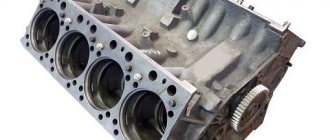
Gas distribution mechanism
Before figuring out how to set the ignition on a T 40 with a fuel injection pump from MTZ, it is advisable to familiarize yourself in more detail with the structure of the gas distribution system of this popular tractor model. The timing belt of the unit is a special unit designed to create optimal conditions for engine operation. Among the most significant elements of its design it is worth noting:
- camshaft;
- gear mechanism;
- valve system and its drive, including springs, rods, pushers, springs;
- fasteners.
An important element of the tractor design, which is necessary for its successful start in low temperature conditions, is the decompressor. In addition to the start, it actively participates when it is necessary to urgently stop the engine. The main elements of its design are levers, slats, and hinges.
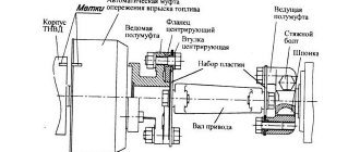
Timing gear diagram
When is it necessary to adjust valves on a tractor?
If the tractor engine is not operated continuously, the valves may last for a long time without requiring repairs. To prevent the valve from breaking when it is torn off along the groove, it is necessary to leave pairs of “crackers” intact if the valve device is dismantled. If gears need to be replaced, they must be inserted into the clutch only as indicated by the manufacturer's markings.
A mechanism such as a decompressor is needed, first of all, to make starting a cold engine easier. In addition, a decompressor is needed when sudden braking of a power plant running on diesel fuel is required. This mechanism is a combination of two control pairs: manual and racks, which are connected to the rack using hinges. The levers are fixed to the forks in a rigid manner.
It is worth noting that the adjustment process is not complicated, but if the tractor is used correctly, it does not need to be done often. This is especially true for D-144 valves (diesel engines) - they are easy to operate and do not require complex manipulations during repair.
Ignition adjustment
If you want to properly adjust this type of mechanism, it is important to note that the ignition system, which is familiar to vehicles with a gasoline-type internal combustion engine, is not available on diesel analogues. Instead of adjustment, you will need to set the injection timing on the T 40 tractor, since in diesel engines the fuel ignites due to excess pressure.
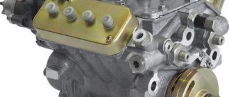
Installation and adjustment of injection timing
When planning to configure such a unit yourself, you will need to prepare a standard set of tools, as well as a special glass tube, the internal diameter of which is 0.1-0.15 cm. To avoid mistakes, you should follow the simplest instructions:
- Disconnect the high pressure pipe from the fitting of the 1st cylinder.
- Place the prepared glass tube on it.
- Turn the crankshaft until the “T” indicator on the cover aligns with the “NDT” position, which can be found directly on the crankshaft pulley.
- Remove the filler neck, and then remove the pump fasteners.
- Set the control lever to the full feed position, then turn out the fuel pump adjusting element until fuel free of air impurities appears in the tube.
- Drain the fuel and note the moment it rises.
- Having installed the pump shaft in the desired position, it is necessary to tighten the bolts so that the holes on the flange coincide with similar objects on the gears.
- Check system functionality.
Using such an algorithm, you can easily adjust the injection timing, but after each adjustment it is necessary to check the operation of the system, since the optimal position often shifts when the bolts are fastened.
Adjustment of valves
Among the necessary manipulations carried out as part of the maintenance of model T-40 tractors is checking and adjusting the valves. During the work, you need to make sure that there is a normal amount of lubricant on the camshaft, as well as that the elements are tightly fastened in their positions.
Tractor gas distribution
The need for maintenance occurs every 380 hours of continuous operation, otherwise there is a high probability of deviations from the norm and serious malfunctions. According to the rules, the valve clearance on a cold power unit should be 0.3 mm, both for the exhaust and intake elements.
The valve adjustment algorithm is extremely simple and involves performing the following manipulations:
- Remove the rear universal joint wedge and then release it.
- Adjustment of the gaps is carried out using a special adjusting screw located on the rocker arm.
- A feeler gauge is used to monitor the current gap and set the required values.
- Rotate the piston of cylinder 1, setting it to the end of stroke position, aligning the mark with the pointer.
- Loosen the locknut, then set the required clearance, and then tighten it again.
- The valves are adjusted according to the order of operation of the cylinders; when moving to the next element, you will need to turn the crankshaft 0.5 turns.
When carrying out work, it is extremely important to ensure that the locknut is securely fastened, otherwise over time this will lead to a shift in the gap, as well as other problems.
Adjustment procedure
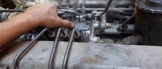
The need to install injection arises when replacing a high-pressure fuel pump (HPF) or installing it after repair, as well as after repairing the piston group of a diesel engine. The adjustment is carried out provided that the fuel equipment, injection pump and the adjusted gas distribution mechanism of the diesel engine are in good working order. The installation process consists of the sequential operations described below.
Installing the first cylinder on the compression stroke
On the right side, in the direction of travel of the machine, in the wall of the engine mounting to the clutch housing, above the longitudinal beam of the tractor frame near the oil filler neck, there is an installation dipstick. With its short threaded part it is screwed into the mounting wall and with its long threadless part it is installed outside.
If it is necessary to install the first cylinder in the “compression” stroke position, the dipstick is installed in the hole, resting its long part against the engine flywheel. Slowly turning the diesel crankshaft, find a position in which the probe will fall into the hole on the flywheel and enter the body of the part completely by 4-5 cm. It is important not to confuse the installation hole with the technological, balancing drillings of the flywheel, which are much smaller in depth. The found position corresponds to an advance of 26 ̊ before the piston of the first or fourth cylinder approaches TDC. This position corresponds to the technical requirements of D 240 for setting the start of fuel injection into the cylinder during the “compression” stroke. To determine which of the cylinders in the first or fourth the “compression” stroke has begun, you need to remove the valve cover. A pair of closed valves will indicate in which of the two cylinders (first or fourth) the “compression” stroke has begun.
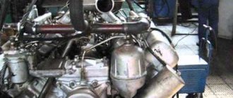
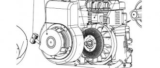
T-40 tractor engine
Production - Vladimir Tractor Plant. The basic version of the vehicle (T-40 is equipped with) the D-37 engine (performance - 37 hp, 27 kW). Its analogue T-40M has a D-144 engine (50 hp, 37 kW). ➤ Type: diesel ➤ Number of cylinders: 4 ➤ Volume: 4.15 l ➤ Cylinder diameter: 10.5 cm ➤ Stroke: 12.0 cm ➤ Frequency: 1500 (37) and 1800 (50) rpm. per minute ➤ Torque: 192 and 205 ➤ Specific consumption during operation. power: no more than 246/248 grams per kilowatt-hour ➤ Starting: electric starter, gasoline PD8 ➤ Cooling type: air As for fuel consumption, it all depends on the load on the engine, as well as on what work the tractor performs. For example, the nominal rate is 7.2 l/hour.
how to set the ignition on T40 | Topic author: Natalya
Artem There's a diesel there. Injection angle.
You adjust the first piston to top dead center, then disconnect the fuel pump, pump diesel fuel into it, start turning it with your hands, as diesel fuel appears from the first fitting, then put it in place and connect the tubes, and start the engine, the injection advance angle on the scale for this engine is where then one or two divisions in the direction of rotation of the fuel pump
Arthur, are you talking about the tractor, so write in more detail.
Valentina On the T 40 there was no ignition and there will not be, but there is an injection moment.
Natalia On T 40 there is no ignition
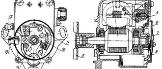
Device
The semi-frame houses a motor, rigidly connected to the gearbox, and there is also a rear axle. The semi-frame is connected to the diesel crankcase with elastic gaskets. It is a load-bearing part of the structure and acts as a shock absorber when driving on uneven terrain. The bevel gear is located behind the clutch, the gearbox shafts are located transversely. Double clutch: the main one is combined with the power take-off clutch. At the rear are the drive and control unit for both shafts (rear and side). The shafts can operate both synchronously and independently. The steering column of the tractor, using a cardan shaft, transmits movement from the steering wheel through the bipod to the power steering and thereby ensures that the guides rotate in the desired direction. The T-40 generator is designed as a three-phase contactless electric machine. It has one-way electromagnetic excitation, voltage regulators and built-in rectifiers.
Other methods of setting up and checking the ignition on a car
You can also set the ignition to spark or independently select the angle when the engine will operate most stably and smoothly. The simplest and least accurate method is to install based on the operation of the motor. To set up, start the engine, after which the nut securing the distributor housing is loosened. Next, you will need to turn the distributor housing clockwise and counterclockwise, finding the position at which the engine runs smoothly and the XX speed is the highest. After this, you should turn the breaker body a couple of degrees clockwise and tighten the distributor nut.
Then the wire contact should be placed near ground (distance about 5 mm) and turn on the ignition. After this, the breaker body should be rotated 20 degrees clockwise. Now the housing needs to be rotated back until a spark appears between the ground and the wire contact. In this position, the distributor body must be secured with the breaker fastening nut.
Upon completion, it is necessary to check the correctness of the OZ in motion. With a warm engine, the car should be accelerated to 40-45 km/h, after which fourth gear is engaged and the gas pedal is fully pressed. Next, it is necessary to assess the degree of detonation. It is considered normal when, immediately after engaging 4th gear, detonation is briefly present (2-3 seconds), but disappears as the car accelerates. If detonation continues after acceleration, then the likelihood of pre-ignition is high. If there is no detonation when the 4th gear is engaged, then the ignition is delayed. In such cases, the SOP adjustment should be repeated to obtain an optimal result.
Expert advice
There are several most common problems characteristic of this type of mechanism. Most often, T 40 owners have to deal with difficult engine starting, as well as excessive exhaust. The main reason is the lack of tightness between the valve and the seat.
To eliminate the damage, you will need to dismantle the heads, and then grind the valve using a machine. A similar problem can be caused by incorrect installation of engine gear elements.
Methods for providing thermal clearance
With an overhead design, the camshaft acts on the valve stem either directly or through a rocker arm. The use of a rocker makes it possible to reduce the difference in the camshaft profile relative to the maximum valve movement when opening. When the camshaft directly impacts the valve stem, the stem experiences significant lateral force, which leads to increased wear. To avoid this, the end of the rod is covered with a special glass, which takes on the lateral force, moving in its own guide seat, and transmits the axial force to the valve. Adjusting washers are installed between the cup and the camshaft cam. If the design has rocker arms, then special adjusting screws with locknuts are installed on them.
Read more: A place in the people's garage
Many modern engines, especially those with more than two valves per cylinder, are equipped with hydraulic valve lash adjusters. In these designs, adjustment of thermal gaps is not required.
The hydraulic compensator allows you to have zero clearance in the drive at any valve temperature
How ICE valves should work
The work cycle of a four-stroke engine consists of four strokes: intake, compression, power stroke and exhaust. Based on the purpose of these strokes, one can understand how the gas distribution mechanism should work: on the intake stroke, the intake valve is open, allowing the fuel-air mixture to enter the cylinder; on the compression stroke, both valves are closed (otherwise you won’t compress); during the working stroke, the valves are also closed so that all the expansion energy of the burning mixture is directed only to moving the piston; During the exhaust process, the exhaust valve is open and the exhaust gases leave the cylinder through it.
Read more: 12 volt electric pump for cars
This is exactly how it would be if the valves had the ability to open and close instantly while the piston is at its dead center, top or bottom. To imagine what an instant is for the period of time during which an engine's operating cycle occurs, we must remember that modern engines easily reach six thousand or more revolutions of the crankshaft per minute. During one working cycle, the crankshaft makes two revolutions, which means that each of the valves opens and closes three thousand times per minute. And the piston ends up in its dead spots six thousand times! For comparison, the rate of fire of the legendary Kalashnikov assault rifle is only six hundred rounds per minute, exactly ten times less! Under such conditions, even a few milliseconds of engine operation is a noteworthy time period during which very important processes occur.
In theory, both valves are closed during the compression and power strokes. In the figure: I - intake stroke, intake valve open; II - compression stroke; III - working stroke; IV - exhaust stroke, exhaust valve open
Setting the ignition timing yourself
Correctly set ignition timing requires adjustment of the OZ. It is necessary to adjust the ignition angle at idle speed. It should be taken into account that the optimal idle speed is considered to be in the range of 850-900 rpm. The ignition timing angle is also within a certain range from -1 (negative) to +1 (positive) degrees. The degree indicated is the degree relative to TDC.
The specified lamp is connected to the positive terminal on the ignition distributor, and is also connected to ground. Next, we will look at the main available methods for setting the ignition using the following example of a domestic “classic”:
Setting up strobe ignition
- the engine must be warmed up until it reaches operating temperature;
- The strobe light is connected to the on-board network;
- unscrew the fixing nut of the ignition distributor-interrupter cover;
- the alarm signal sensor is placed on the high-voltage wire of the first cylinder;
- if there is a vacuum corrector hose, you will need to remove and plug the specified hose;
- the strobe light is directed to the crankshaft pulley;
- the engine starts and idles;
- the distributor body is rotated;
- the position of the breaker-distributor body is fixed so that the pulley mark coincides with the corresponding mark on the timing belt;
- after aligning the marks, the fixing nut is tightened;
Setting the OZ according to the control light
If you use the light bulb ignition method, then you need to turn the engine crankshaft so that the mark on the crankshaft pulley matches the mark on the timing cover. In this case, the slider on the ignition distributor should point to the spark plug wire of the first cylinder.
Next, the distributor lock nut is loosened, after which one wire from the light bulb is connected to the wire that goes to the ignition coil from the distributor. The second wire from the lamp is installed to ground. Then you need to turn on the ignition and rotate the distributor body clockwise until the control lamp stops lighting. After this, you should carefully turn the distributor body back, that is, counterclockwise. Having determined the position at which the light bulb lights up, it is necessary to fix the distributor body in this position. Fixation is done by tightening the distributor nut.