The use of an air pneumatic relay allows you to automate the filling of the compressor receiver with compressed gas. The operator of equipment with a pressure switch does not need to monitor the process, trying to fix the limit parameters. As a result, engine damage is prevented. Significant results, right?
If you are planning to purchase a pressure switch for your compressor, then you have come to the right place. Here you will find a vast amount of extremely useful information about the principles of operation of the device, its configuration and connection methods.
We have described in detail the existing types of pneumatic relays. They provided options for connecting to a household and industrial network with extremely clear diagrams. We looked at typical breakdowns and ways to prevent them. The information and useful tips we provide are supplemented with graphic, photo and video applications.
Operating principle of a pressure switch
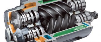
The name of the relay is determined by its purpose - controlling a piston compressor to maintain the required atmospheric pressure in the receiver. It is rarely found on a screw type device responsible for compressing and supplying air.
I take into account the magnitude of the pressing force in pneumatic automation; the device acts on the voltage line, closing or opening it. Thus, insufficient pressure in the compressor starts the motor, and when the required level is reached, it turns it off.
This standard operating principle, based on connecting a normal closed loop to a circuit, is used to control the motor.
The design of all ejectors contains a cylinder containing air at a certain pressure. Reducing it requires turning on the engine to replenish the supply. If the situation is the opposite and an excess is detected, the supply is stopped so that the container does not burst. These processes are controlled by a pressure switch
Modifications with the opposite operating algorithm are also presented: when reaching minimum values in the compression circuit, the pressure switch turns off the electric motor, and at maximum values it activates. Here the system operates in a normally open loop.
The operating system is made up of spring mechanisms with varying degrees of rigidity, reproducing the response to fluctuations in the air pressure unit.
During operation, the indicators formed as a result of the elastic force of tension or compression of the springs and the pressure of the atmosphere pressed by the device are compared. Any changes automatically activate the action of the spiral and the relay unit connects or disconnects the electricity supply line.
However, it is worth considering that the design of the review model does not provide for regulatory influence. Exceptional impact on the engine. In this case, the user has the opportunity to set a peak value, upon reaching which the spring will fire.
Principle of operation
The operating principle of the automation unit is simple. The device is mounted on a pipe communicating with the receiver. The spring-diaphragm pressure switch sensor for the compressor continuously measures the pressure. As soon as it drops below the set value, the sensor rod, under the action of a spring, closes the contacts of the compressor relay and the electric motor is connected, pumping air into the tank. After reaching the set pressure, it presses the rod and opens the contacts, turning off the engine. Adjustment of these values is available to the user. In addition, when the operating pressure limit is reached, the safety valve included in the device is activated, releasing excess air from the compressor into the atmosphere.
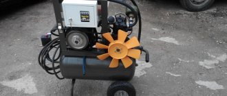
Complete set of compressor automation unit
The relay design is a small-sized block equipped with receiving pipes, a sensing element (spring) and a membrane. Mandatory subassemblies include an unloading valve and a mechanical switch.
The pressure switch sensing unit is made up of a spring mechanism, the compression force of which is changed by a screw. According to the factory standardized settings, the elasticity coefficient is set to a pressure in the pneumatic chain of 4-6 at, as reported in the instructions for the device.
Inexpensive models of ejectors are not always equipped with relay automation since such devices are mounted on the receiver. However, during long-term operation, to eliminate the problem of overheating of engine elements, it makes sense to install a pressure switch
The degree of rigidity and flexibility of the spring elements is subject to the temperature of the environment, therefore absolutely all models of industrial devices are designed for stable operation in an environment from -5 to +80 ºC.
The reservoir membrane is connected to the relay switch. During movement, it turns the pressure switch on and off.
The unloading unit is connected to the air supply line, which allows excess pressure to be released into the atmosphere from the piston compartment. This relieves the moving parts of the compressor from excessive force.
The unloading element is located between the ejector check valve and the compression block. If the motor drive stops working, the unloading section is activated, through which excess pressure (up to 2 atm) is released from the piston compartment.
With further start or acceleration of the electric motor, a pressure is created that closes the valve. This prevents overloading of the drive and simplifies starting the device in switched off mode.
There is an unloading system with a time interval of activation. The mechanism remains in the open position when the engine starts for a specified period. This range is enough for the engine to achieve maximum torque.
A mechanical switch is required to start and stop the automatic system options. As a rule, it has two positions: “on.” and "off". The first mode turns on the drive and the compressor operates according to the established automatic principle. The second one prevents accidental starting of the engine, even when the pressure in the pneumatic system is low.
Shut-off valves allow you to avoid emergency situations when elements of the control circuit fail, for example, a breakdown of the piston unit or a sudden stop of the motor
Safety in industrial structures must be at a high level. For these purposes, the compressor regulator is equipped with a safety valve. This ensures system protection in case of incorrect relay operation.
In emergency situations, when the pressure level is higher than the permissible norm, and the telepressostat does not work, the safety unit comes into operation and vents the air. Safety valves in heating systems operate according to a similar scheme, the operating principles and devices of which are described in the article we recommend.
Optionally, a thermal relay can be used as additional protective equipment in the review device. With its help, the strength of the supply current is monitored for timely disconnection from the network when parameters increase.
To avoid burnout of the motor windings, the power is turned off. The nominal values are set using a special control device.
Device
All components of the compressor pressure switch are assembled in a compact unit, covered with a plastic or metal case. The product includes:
- Inlet and outlet pipes.
- The sensitive element is a spring and a membrane.
- Stock. Connected to the membrane and placed inside the spring coils.
- Contact Group.
- Adjustment screws.
- Unloading and safety valve.
- Mechanical switch.
The elasticity of the spring, and, consequently, the sensitivity of the sensor, depends on the ambient temperature; most devices are designed to operate in the temperature range from -5 to +70 °C.
The unloading unit is designed to release air from the compressor cylinders after it stops. Thereby:
- its subsequent launch is facilitated;
- wear of piston group parts is reduced;
- the service life of the entire unit is extended.
When the unloading valve is activated in the silence that follows after the compressor stops, a sharp characteristic sound is clearly audible.
The mechanical switch serves for the initial start and final stop of the compressor. It has two positions: “On” and “Off”. “On” activates automatic operation systems. It transfers further control of the compressor to the pressure switch. The “Disabled” position prevents spontaneous starting of the motor when the pressure in the receiver drops below the set value.
The safety valve allows you to release excess pressure into the atmosphere in the event of a relay failure and avoid compressor breakdown in this case.
A thermal relay can serve as additional protection for the compressor motor. It is included in the automation unit; it disconnects the motor windings from the supply voltage in the event of an increase in current strength, indicating an overload of the motor.
Setting up an air compressor comes down to setting the operating pressure with an adjusting screw. The pressure regulator has values marked on it. Pressure can be controlled more accurately using a pressure gauge.
Types of pressure switch devices
There are only two variations in the design of the automatic compressor unit. The determination is made based on their operating principle. In the first version, the mechanism turns off the electric motor when the established limits of the air mass pressure level in the pneumatic network are exceeded. These devices are called normally open.
Schematic structure of a membrane pressure switch: 1 – pressure converter; 2 and 3 – contacts; 4 – piston; 5 – spring; 6 – membrane; 7 – threaded connection
Another model with the opposite principle - turns on the engine if a drop in pressure is detected below the permissible level. Devices of this type are called normally closed.
Design and principle of operation of the pressure regulator
A gas pressure regulator or pressure reducing valve is designed to reduce the pressure in the line diverted from the main line and maintain this pressure at a constant level.
Pressure regulators are used to maintain the pressure required for the operation of pneumatic, gas or other equipment.
For example, pressure reducing valves are installed on gas cylinders and allow you to adjust the required pressure in the line discharged to the consumer. Reducing valves installed on cylinders are often called pressure reducers, since they reduce or reduce the pressure in the outlet line (reduction - reduction, reduction, reduction).
Structure of pneumatic relay symbols
The marking of the air pressure switch indicates the entire optional set of the device, design features, including information about the factory settings for the pressure differential.
Condor's production models offer a wide range of pressure control equipment. The MDR series is aimed at using ejectors of various powers
Let us examine the designations in more detail using the example of devices for air ejectors RDK – (*) (****) – (*)/(*):
- RDK – series of relays for compressors;
- (*) – number of threaded ports: 1 – one port with 1/4”NPT internal thread; 4 – four connectors;
- (****) - type of housing design: T10P - version 10 with a “lever” switch; T10K – “button” switch; T18P – execution 18 with a “switch” switch; T19P - 19 s;
- (*) – factory settings of the threshold response: 1 – 4…6 bar; 2 – 6…8 bar; 3 – 8…10 bar;
- (*) – diameter of the unloading valve: the absence of a symbol means a standardized parameter of 6 mm; 6.5 mm – 6.5 mm.
The difference between the minimum and maximum pressure thresholds is set by the manufacturer and, as a rule, has a value of 2 bar.
However, it is also possible to manually adjust the range of two values – maximum and minimum, but only downward.
The specifics of setting up pressure switches for pumping stations are outlined in the following article, the contents of which we recommend that you familiarize yourself with.
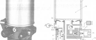
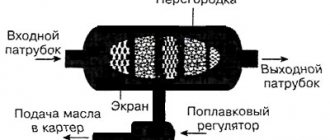
Pressure regulator device
The schematic diagram of the pressure regulator is shown in the figure.
A spring 1 is installed in the valve body, the preload of which is adjusted by screw 2. The spring, through the membrane 3 and the pusher 4, acts on the seat valve 7, which is affected by the spring 8 in the opposite direction.
The outlet pressure depends on the size of the gap between valve 7 and seat 5; in addition, it acts on membrane 3 through channel 6.
The presented valve has two channels, inlet and outlet, which is why it is called two-line .
Pressure regulator with filter
This device combines a pressure reducing valve and a filter that cleans compressed air from impurities, dirt particles, and dust. More information about the design and operating principle of such a regulator (RDF) can be found here https://izpk.ru/reduktor-rdf-3-1-rdf-3-2.
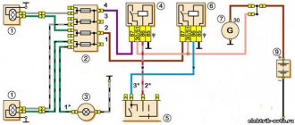
Air relay connection diagrams
The compressor pressure switch is manufactured for connection to electrical circuits of different loads. In accordance with the rating of the power supply line, the appropriate model of the relay unit is selected.
Option #1: to a network with a nominal value of 220 V
If the drive motor is a single-phase device, then a 220 V relay with two groups of contacts is installed.
To work with a single-phase load, manufacturers recommend equipping the unit using models of the RDK series: xT10R-x; xT10K-x; xT19P-x, since these devices have two contact groups
Option #2: to a three-phase network with a voltage of 380 V
For a three-phase load of a 380 V circuit, one of the options can be used: a modification of the relay for 220 V or 380 V, with three contact lines, to simultaneously disconnect all three phases.
Both methods have different schemes. Let's consider the first option:
To operate in a three-phase electrical circuit, a pressure switch RDK-xT18P-x is used. This model is equipped with three contacts and facilitates simultaneous switching of all phases
By choosing the second method, power is supplied from one phase (zero) and in this case the relay rating should be 220 V. For more details, see the following diagram:
It is allowed to use telepressostats of the RDK series: xT10R-x, xT10K-x and xT19P-x with a three-phase load, however, the use of such a circuit requires incomplete disconnection from the supply network. More specifically, one phase will be permanently connected to the load
After connecting to the power supply, you need to understand the additional capabilities provided in the air blocks for ejectors.
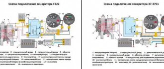
Purpose and location of the pneumatic system pressure regulator
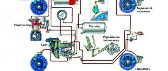
On domestic and foreign trucks, a pneumatic braking system is widely used, which also supplies compressed air to a number of other components and assemblies - the dump platform control system, clutch, sound signal, etc. All these components are built in such a way that they work normally only within a certain pressure range, and if the pressure goes beyond this range (becomes higher or lower), then their operation will become impossible. And an excessive increase in pressure is even fraught with breakdowns.
Therefore, the pneumatic system of trucks must have a component that ensures that the air pressure is always maintained within the operating range. This problem is solved by a unit that is simple in design and principle of operation - a pressure regulator. The pressure regulator performs three functions:
- Disconnects the compressor from the pneumatic system if the pressure in it reaches the maximum permissible value;
- Connects the compressor to the pneumatic system if the pressure in it drops below the minimum permissible value;
- Protects the pneumatic system from excessive pressure growth if, for one reason or another, the compressor was not turned off when the maximum permissible pressure was reached (performs an emergency pressure release).
In most domestic trucks and buses, the pressure range is as follows:
- The minimum operating pressure at which the compressor is connected to the pneumatic system is 600-650 kPa (6-6.5 atmospheres);
- The maximum operating pressure at which the compressor is disconnected from the pneumatic system is 730-800 kPa (7.3-8 atmospheres);
- The maximum permissible pressure at which pressure is released is 1000-1300 kPa (10-13 atmospheres).
The pressure regulator is an important part of the pneumatic system of any truck; the regulator, in principle, makes the operation of the pneumatics possible and protects it from damage, but at the same time has a fairly simple design and principle of operation.
Installation of relays and auxiliary elements
In some modifications of pressure switches, you can find additional equipment in the form of flange connections, through which additional equipment is connected. These are basically three-way parts, with a ¼-inch diameter.
By means of several flange connectors, additional elements can be introduced into the system: safety valve, pressure gauge and other necessary mechanisms
To put the device into operation, it must be connected to the receiver. Installation consists of the following steps:
- The device is connected to the compressor through the main outlet.
- A pressure gauge is connected to the device with flanges. There may also be other auxiliary mechanisms that require activation: a safety or unloading valve.
- Channels that are not used for connection must be closed with plugs.
- Next, according to the electrical diagram, the relay is connected to the contacts of the motor control circuit.
Motors with low power can be connected directly; in other cases, additional installation of an electromagnetic starter of appropriate power is required.
Before moving on to setting the threshold response parameters, it is worth paying attention to the operating conditions. First, adjustments are made under pressure. Secondly, the electrical supply to the engine must be cut off.
Three-line pressure regulator
A regulator that, in addition to the input and output channels, also has an additional one - to vent air during a critical increase in pressure - is called a three-line regulator.
The design of this regulator differs from the design of a two-line regulator by the presence of a hole in the membrane, which opens if the pressure exceeds a critical value. Under normal conditions, the regulator works the same as a two-line regulator.
If the outlet pressure increases to a value sufficient to move the diaphragm to its highest position and open the relief channel. The gas is released into the atmosphere through this channel. The pressure in the discharge line is reduced until the spring force is sufficient to close the relief channel.
Since excess pressure is released into the atmosphere, three-line regulators of the presented design are used to regulate air pressure.
Thus, the principle of operation of the gas pressure regulator is similar to the principle of operation of the hydraulic pressure reducing valve shown in the video.
Adjustment and commissioning process
Factory set parameters do not always meet consumer requirements. In most cases, this is due to insufficient compression force at the highest point of disassembly.
The operating range of the pressure switch may also not be suitable. In this case, independent adjustment of the actuator will be relevant.
Standard factory settings: upper limit 2.8 atmospheres, lower limit 1.4 bar. The parameters are monitored visually using a pressure gauge included in the standard pressure switch kit. New models, for example, Italtecnica, have a transparent body and are equipped with a compression scale indicator directly on the relay
To begin setting the operating compression value, you will need to inspect the engraved plate, which indicates the parameters of the electric motor and compressor.
We only need the largest value that the device produces. This indicator indicates the maximum pressure force that can be set on the relay for the correct operation of the entire pneumatic system.
If you set the specified value (in the figure 4.2 atm), then taking into account all factors - differences in power supply, exhaustion of the service life of parts, etc. - the compressor may not reach the maximum pressure, and accordingly it will not turn off.
In this mode, the working elements of the equipment will begin to overheat, then deform and eventually melt.
The maximum ejector value must be taken into account when determining the maximum relay value. This indicator should be less than the rated pressure of the compressor. In this case, all elements of the system will work uninterruptedly
For reliable operation without shutdowns, it is necessary to set the highest shutdown pressure on the relay, which does not reach the nominal value engraved on the compressor, namely 0.4-0.5 atm lower. According to our example - 3.7-3.8 atm.
The pressure limits at which the compressor is turned on/off are regulated by a single bolt. In order not to make a mistake with the choice of direction for increasing/decreasing, arrows are placed on the metal base
Having determined the level that will be set, it is necessary to remove the relay housing. Under it there are two adjusting elements - a small and a large nut (in Figure 1.3).
Nearby there are arrow indicators for the direction in which the twists will be made - thereby compressing and unclenching the spring mechanism (2.4).
A large screw clamp and spring are provided to control compression settings. When twisted clockwise, the spiral compresses - the compressor switch-off pressure increases. Reverse adjustment - weakens, and accordingly, the pressure level for shutdown decreases.
It is worth remembering: by increasing the shutdown compression strength, we are changing the factory settings, which were set taking into account the regulatory requirements for the operation of the equipment. Before making adjustments, check the technical documentation of the device so as not to exceed the limits stated by the manufacturer
When reproducing settings, the receiver must be at least 2/3 full.
Having understood the purpose of the elements, let's proceed:
- To ensure the proper level of safety, we turn off the power supply.
- Changing the compression level of the springs is done by turning the nut several turns in the required direction. On the board, near the large-diameter adjusting screw, according to the standards, there is a symbol in Latin letters P (Pressure), a smaller one - ΔР.
- The adjustment process is monitored visually on a pressure gauge.
For convenience, some manufacturers place the adjusting fittings for changing the nominal value on the surface of the device body.
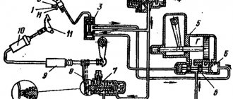
Operating principle of the pressure regulator
The design of the regulator is shown in the figure.
The main element of the pressure regulator is the measuring membrane 4, fixed in the housing 6. The rigid center of the membrane 7 is connected on one side by a spring 1 with a control screw 8 and a handle 5, and on the other side by a rod 3 with a poppet valve 9 supported by a spring 2. The rod 3 has a groove connecting the output of the gearbox to chamber B. Spring 1 acts on the membrane 4 (the change in the impact force is made by the handle 5), and through it the rod 3 on the poppet valve 9 and the support spring 2. If the force created by the control spring 1 exceeds the force created support spring 2, then valve 9 comes off the seat and passes compressed air from the regulator inlet to its outlet. Poppet valve 9 will be open until the total force created by the pressure in chamber A on the measuring membrane 4 (the pressure in chamber A is equal to the pressure at the outlet of the regulator), the force of the support spring 2 and the force of pressing the poppet valve created by the pressure in chamber B (pressure in chamber B is equal to the pressure at the outlet of the air reducer) will not exceed the force created by the control spring 1. The total force is determined by the output pressure and the force of the pressing spring 2, i.e. as soon as the pressure at the outlet of the regulator exceeds the set value, poppet valve 9 cuts off the outlet of the regulator from its input, thereby preventing further growth of the outlet pressure. When (due to the consumption of compressed air) the pressure at the outlet of the regulator drops below the set value, poppet valve 9 opens and the pressure rises to the set value, i.e. and the set pressure is maintained.
Possible malfunctions of the device
Several malfunctions characteristic of pressure switches are noted. In most cases, they are simply replaced with new devices. However, there are minor problems that you can fix yourself without the help of a repairman.
If the cause of the malfunction was determined to be a pressure switch, the technician will insist on replacing the device. All service actions for cleaning and replacing contacts will cost the user more than purchasing and installing a new device
The most common malfunction is characterized by air leakage from the relay when the receiver is turned on. In this case, the culprit may be the start valve. It is enough to replace the gasket and the problem will be eliminated.
Frequent starting of the compressor indicates loosening and displacement of the adjusting bolts. Here you will need to double-check the threshold for turning on and off the relay and adjust them according to the instructions in the previous section.
Types and applicability of pressure regulators
All pressure regulators can be divided into three categories according to the type of valves used in them:
- Regulators with poppet valves;
- Regulators with ball valves;
- Regulators with both types of valves.
Today, all types of regulators are used, but the most common are regulators that use a combination of ball and poppet valves. Typically, inlet and outlet valves are made of ball valves, and discharge and check valves are made of poppet valves.
Also, all regulators can be divided into two large groups:
- Regulators allowing the installation of a silencer;
- Regulators without silencer.
Today, regulators of the first type are common, and many of them go on sale with a silencer already installed. Due to the simplicity of the device and the availability of the silencer, the regulators equipped with it are practically no different in price from simple regulators.
The great advantage of pressure regulators is their versatility. The same regulator can be used with equal success on almost all models of domestic trucks and buses - ZIL, KrAZ, KAMAZ, MAZ, Ural, LiAZ, PAAZ, etc. However, when installing a regulator on a specific car, it is often necessary to make some adjustments, which does not cause problems for experienced drivers.
Troubleshooting methods
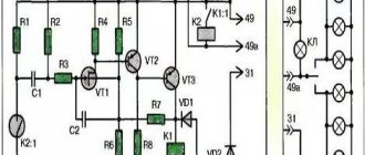
A more difficult problem lies ahead if the compressor does not work. There may be several sources. Let's consider one of them - melting of the pressure switch contacts due to erosion arising from electrical sparks.
Burning of the contact group occurs due to electric spark erosion, which is formed as a result of the opening of the contacts. However, it is not always possible to replace elements - some modifications are no longer available for sale
To eliminate this type of malfunction, you can use one of the following methods: clean the surface, which extends the service life by at least 3 months, or repair it by replacing the contacts in the terminal clamps.
Step-by-step instructions for the second option:
- Bleed all air from the receiver and turn off the power to the ejector. Remove the pressure switch.
- Having removed the protective housing, disconnect the wiring connected to the group of contacts.
- Using a screwdriver, you need to remove the terminal with contacts and drill out the burnt lines from it.
- You can replace the wire with copper wire. It is necessary to select it taking into account the diameter of the hole, since it must fit tightly into the seat. It is inserted into the hole and pressed on both sides.
- Similar actions are performed with the remaining burnt lines.
- After the contact group is assembled, it is mounted in its original place and the pressure switch cover is screwed on.
The compressor relay operates in difficult conditions, subject to wear and failure.
Although the repair is not cost-effective, those familiar with the device can perform the repair themselves. However, the option of replacing it with a new device still remains profitable.
How does a pressure regulator work?
In the initial state, gas enters the valve inlet, flows in the gap between the seat and the valve, and enters the outlet. The amount of clearance is determined by the degree of spring preload, which is changed using an adjusting screw. It turns out that the outlet pressure depends on the inlet pressure and the size of the gap between valve 7 and seat 5.
If the outlet pressure increases, then under its influence the membrane will move and compress the spring, which, in turn, will move valve 7, and the flow area will decrease. The pressure loss across it will increase, which will cause the pressure in the discharge line to drop to the setting value.
If the pressure at the outlet of the regulator drops below the set value, the pressure with which the gas acts on the membrane will decrease, as a result, the preload of spring 1 will decrease. Valve 7 will move and increase the flow area. Losses on it will decrease, which will cause the pressure in the discharge line to increase to the setting value.
How does a regulator maintain pressure at a constant level?
It turns out that the pressure in the outlet line is maintained at a constant level due to changes in the amount of losses on the regulator. The regulator is adjusted using an adjusting screw, which changes the preload of spring 1; the control effect on the valve through the membrane is exerted by the gas pressure from the discharge line.
The regulator outlet pressure is defined as the difference between the inlet pressure and the pressure loss across the valve.
Adjustments and main malfunctions of the pressure regulator
To ensure normal operation of the pneumatic system, the pressure regulator must be adjusted, and this can be done several times - when repairing or installing a new regulator, when replacing individual components and assemblies of the pneumatic system, when the regulator malfunctions for one reason or another, etc.
Most pressure regulators have two settings:
- Setting the minimum operating pressure (that is, the regulator switch-on pressure) is done using an outward bolt that rests on the balancing spring cup. When the bolt is tightened, the spring is compressed, so the minimum pressure at which the regulator turns on increases; when the bolt is unscrewed, the pressure, on the contrary, decreases. In some models of regulators, the minimum switching pressure is set using an adjusting cap that covers the spring;
- Setting the maximum operating pressure (that is, the regulator shut-off pressure) is done in various ways depending on the regulator model. Typically the adjustment involves changing the number of shims placed between the intake and exhaust valve seats, or under the relief valve spring.
Adjustment is made according to the recommendations of the car manufacturer; pressure ranges are monitored using a pressure gauge on the dashboard. It is also necessary to evaluate the frequency with which the compressor is connected and disconnected from the pneumatic system (each disconnection is manifested by a characteristic hiss of air).
Over time, malfunctions may occur in the pressure regulator; the most common problems are the following:
- Valve wear;
- Clogged channels;
- Clogged filters;
- Sagging or breakage of springs;
- Failure of various regulator components.
All malfunctions are manifested in one way or another by a deterioration in the operation of the regulator, a change in the range of operating pressures with the impossibility of adjusting them, or a complete failure of this unit, and with it the inoperability of the pneumatic system. The breakdown can only be determined after removing and disassembling the pressure regulator. If the channels or filters are clogged, the regulator can be easily restored to working condition, but in the event of wear and tear of parts, it is easier to purchase and install a new regulator.
To ensure reliable operation of the vehicle's pneumatic system, the pressure regulator should be periodically checked, and, if necessary, the limits of the operating pressure range should be set. In this case, the vehicle's pneumatic systems will operate for a long time and reliably, providing the necessary performance characteristics and safety.