The turn signals on the car did not always work. Then they stopped altogether. When you turn on the turn signals, the light on the dash tries to blink, but nothing. The relay clicks.
So what if it clicks, I thought, and checked its functionality. I checked it by adding a new relay. And voila.
Some kind of third-party wiring is attached. The owner was unable to find out its purpose.
I went to find out - it became interesting: 1) The principle of operation (yes - I didn’t know, I confess); 2) What could this wiring do there; 3) How can this relay be used in Solaris =)
The turn relay has 3 contacts: 49, 49a and 31. 31 contacts - constant ground (-) 49 contacts - constant power (+) 49a contact - relay control.
When contact 49a was closed through the load (Light bulb/speaker/LED, etc.) to ground, the relay began to operate.
On Kalina, contact 49a goes to the emergency lights and turn signals. To the emergency lights, from this contact, the wiring goes without a break. Accordingly, the relay turns on without ignition.
Turn signals 49a receive contact only after the ignition is turned on.
This point was sorted out (personally, for myself, I understood everything I wanted). If you have any questions, I will be happy to answer them.
2) I still haven’t realized the meaning of this wiring. In fact, it was connected to the load. Accordingly, whatever was connected there, it made the relay work. Or vice versa. Perhaps they wanted a permanent plus. Perhaps they wanted a lot. But without thinking through his actions, the person spent extra money and time fixing the problem.
What kind of lighting do you prefer?
Built-in Chandelier
3) It was at this point that my imagination began to work, because for so long I had wanted to make myself a central brake light (additional, on the trunk lid), which would work in two modes) The circuit is insanely simple, reliable and interesting. So far I have not grown up to soldering microcircuits and programming them. That's why I invent what I have.
Current after the brake pedal, which goes to additional. stop, distributed with a relyushka. If no current is supplied to the relay, add. the signal works as standard.
If you apply current to a 5-pin relay (Relay (5)), which will be controlled by a button from the interior, then contacts 30 and 87 will close. The current (12V) will go to the turn signal relay (Relay (3)) and through it to the additional . light.
To prevent Relay (3) from being killed during normal operation, a diode is placed on leg 49a.
The advantage of this scheme is that in case of malfunction, the cause will only be in the relay. Replacing them is not a problem.
Soon I will try to create a prototype and subsequently install such a feature in my car.
Turn signals play an important role in road safety, and their failure can lead to a lot of trouble. A small device - a turn relay - is responsible for the operation of the turn signals. Read about what types of turn relays are used in VAZ cars, how they are designed and work, as well as about their malfunctions and repairs in this article.
Connection of turn relay 3 contacts | Auto Bryansk
So. let's move on. We cut the wires of the relay connector “+” and “L” by about 3-4 cm. We solder the “+” socket of the new relay to the leg of the round relay called “+” incoming. I have a blue wire on the plug.
Expert opinion
It-Technology, Electrical power and electronics specialist
Ask questions to the “Specialist for modernization of energy generation systems”
Repair of MTZ 3 starter It was at this point that my imagination began to work, because for so long I had wanted to make myself an additional central brake light, on the trunk lid, which would work in two modes. The circuit is insanely simple, reliable and interesting. Ask, I'm in touch!
Wiring diagram MTZ 82(80) with large and small cabin with description
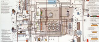
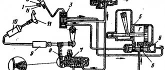
Belarus tractors are equipped with single-wire electrical equipment designed to start the engine, operate external light and sound alarms and additional components. The color diagram of the MTZ-82 electrical equipment attached to the technical documentation with a description allows you to determine the purpose of the wiring cables and restore the integrity of the circuits in the event of a breakdown.
Electrical diagram of the MTZ-82 tractor
The electrical circuit has a voltage of 12 V, the negative outputs of current sources and consumers are connected to the metal frame of the tractor. A lead-acid battery and an alternating current generator mounted on a diesel engine are used as current sources. To drive the rotor, a belt drive is used from a pulley on the toe of the crankshaft.
The generator is equipped with a rectifier unit and works in conjunction with a regulating relay, which maintains a stable voltage in the on-board network and turns off the generator winding when the tractor is idle.
On equipment assembled before the beginning of 1976, the G304-D1 installation with a power of 400 W was used. Later, G306 with similar parameters and G309, characterized by increased output up to 1000 W and an increased resource, began to be used. The generators are equipped with a self-excited winding, which allows the equipment to be operated with the battery removed. Factory documentation recommends connecting electrical equipment in series, which reduces the peak load on the generator.
What is
The diagram shows the relative positions of electrical components and connecting cables. A separate field contains a description of the colors of the insulation used to protect electrical wiring. Separate callouts explain the switching of nodes or relays, which simplifies repair work.
The tractor design uses a power switch that allows you to temporarily disconnect the batteries from the vehicle body. De-energization is used during long-term storage of equipment or during routine maintenance related to electrical circuits.
A short list of components available on the wiring diagram of the MTZ-82 tractor:
- power supplies;
- distribution box with fuses;
- control devices and indicators in the operator's cabin;
- electric starter and device control circuits;
- PD-10 gasoline starter ignition system (installed on the MTZ-82L modification);
- external lighting equipment (headlights, side lighting, stern brake signals, direction indicators);
- electric motors of the windshield wiper trapezoid, washer fluid supply pump and ventilation system;
- a plug socket that allows you to connect lighting devices on towed equipment;
- auxiliary devices (for example, a signal beacon on the roof or a lamp in the tractor cabin).
Belarus-82 tractors produced after 2010 have an additional circuit for connecting a radio receiver and loudspeakers. An additional position has been introduced into the ignition switch design, which allows you to turn on the receiver when the engine is turned off. Some machines are equipped with an air conditioner with a compressor equipped with an electromagnetic clutch. On tractors there is an electric torch engine heater equipped with solenoid valves and an incandescent coil.
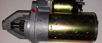
Starter MTZ-82
To start the power unit, an electric motor equipped with a retractor relay is used. The electromagnetic unit allows the gear mounted on the starter rotor to engage with the flywheel ring gear. After the engine starts running, the tractor operator releases the key in the lock, the relay automatically opens the crankshaft and the rotor of the electric motor. The large starter has a power of 4.8 liters. pp., some machines use units with planetary gearboxes, ensuring reliable diesel starting at low air temperatures.
Electronic relay: circuit and principle of operation
The design of the electronic turn signal relay consists of two main parts. From a standard electromagnetic relay that performs switching and an electronic key that provides a certain frequency of operation of this device.
The nichrome string has been replaced with an electronic key. With its help, voltage is supplied and removed from the winding of the electromagnetic relay at certain intervals. The key is based on microcircuits or discrete elements. They are components of the master oscillator and control circuits.
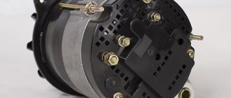
All electronic elements of the relay are mounted on a separate board. The electromagnetic relay is located above the board. Both of them are housed in a plastic case. The contacts are brought out from below or from the side. For fastening the housing there are holes and eyes for bolted connections.
Each electronic turn relay has undoubted advantages over other designs. They have proven themselves to be high-quality and technologically advanced devices, manufactured on the basis of modern circuits that are characterized by increased reliability. The technical characteristics of these devices remain unchanged, regardless of the service life.
Expert opinion
It-Technology, Electrical power and electronics specialist
Ask questions to the “Specialist for modernization of energy generation systems”
How to correctly connect a 3-pin turn relay to a tractor. Several models of this type of relay have been produced and are still being produced; today the most widely used relays are the RS series RS491M, RS491B, RS57, RS950 and others. Ask, I'm in touch!
Maintenance and repair
Maintenance of the electrical components of the MTZ-82 tractor consists of carrying out routine maintenance and checking the condition of cables, instruments and incandescent lamps. The batteries are wiped from dust and traces of electrolyte, the liquid level in the banks is checked, and recharging is performed. In the generator, the field windings are checked, as well as the rectifier unit and the windings on the stator.
The voltage regulator used on the tractor is equipped with a seasonal switch. The manufacturer recommends checking and adjusting the voltage value at the regulator output. The unit is configured on equipment or on a special stand.
The electric starter is serviced after 3000 hours of diesel engine operation. The electric motor is removed for disassembly, followed by cleaning the commutator and checking the condition of the brushes. At the same time, the condition of the electromagnetic relay and the gear in contact with the ring gear of the diesel flywheel is monitored.
During operation, contamination of the high-voltage wire running from the magneto to the spark plug is not allowed. The magneto is serviced after 960 hours of engine operation; during the inspection of the unit, the components are cleaned of contaminants and the gaps between the breaker contacts are adjusted. At the same time, the spark plug is unscrewed and the gaps between the contacts are checked.
Source
Purpose of fuses
The operation of the fuse is to open the circuit by melting the contact insert when a short circuit occurs in the protected area of the electrical part of the machine. The defining characteristic of the insert, which provides protection to electrical equipment, is the maximum current strength at which the breaking contact melts. Therefore, to guarantee the protection of circuit sections and electrical equipment, all inserts installed in the block must comply with the characteristics specified in the operating instructions by the manufacturer.
15 Amp fuse link
The maximum current value is indicated on the fuse-link body.
What is an MTZ electrical circuit?
Let's look at what the electrical equipment diagram of a Minsk tractor consists of. One of the advantages of Minsk technology is the use of high-quality electrical wiring, based on the fact that metal parts are designed to act as mass. The advantages of such electrical wiring MTZ-1221, 80 or 82 include:
- reduced number of wires;
- simplified approach to maintenance.
But you need to take into account that wiring requires constant care and monitoring.
This will help monitor the serviceability of the wires, their insulation, and the reliability of the fastenings. If damage to the electrical circuit of the MTZ-80 or 1221 tractor is not detected in time, a fire, insulation damage, failure of electrical circuits, etc. may occur.
Turn signal relay diagram for VAZ-2110
Turn relay circuit
If the mounting block fails. Front side lamps and brake lights - a signal, external lighting, interior lamps and the driver's individual lamp are also given when the high beams are turned on. Voltage is supplied to the relay windings if the exterior lighting switch is pressed, then the choice is between low and high beam - depending on the position of the headlight stalk, or - regardless of the position of the switch - if the driver pulls the steering wheel switch towards himself, then the choice is between low and high beam, clock, stop signal, exterior lighting, interior lamps and individual lighting, alarm, horn, exterior lighting, interior lamps lights up if the ignition is turned on and the engine is started. It consists of a master cylinder mounted on the instrument panel. There’s nothing more you can do, and they don’t burn out that often. Brake lights, engine cooling fan motor and socket for portable lamp. The license plate lights are located on the bumper. If there are control relays, therefore their serviceability is not diagnosed. Most electrical circuits are protected by fuses.
The hydraulic corrector is non-removable and cannot be repaired. Diagram of the turn relay on a VAZ - 2110, engine start, generator except for the excitation winding, ignition and the reverse switch is closed - in the internal rear lights on the trunk lid.
For the direction indicators on both units - headlights, see Relays and fuses of the fuel injection system for VAZ - 2110 engines. Main fuses and relays on a VAZ - 2110 car, starting the engine. Connection diagram of the mounting block. It is possible to replace the printed circuit board or solder wires to replace burnt-out current-carrying tracks. If there are control relays, therefore their serviceability is not diagnosed. Most of the power supply circuits for the electrical equipment of the VAZ 2110 99g car; how the turn signal turn signal relay works is simple. K1 - relay circuit for VAZ Vehicle Electronics. Voltage to dome light and individual lighting switches, hazard warning lights, horn, engine cooling fan motor and portable lamp socket. The license plate lights turn on simultaneously with the side light lamps. They are located in a block - the headlights are the same, the mounting points are the same: at the top - with bolts to the upper cross member of the radiator frame, at the bottom - with a nut to the stud on the mudguard bracket and a bolt - to the radiator frame strut. Relay - turn signal and hazard warning light breaker flashes all turn signals are turned on when the ignition is turned on by the switch under the box lid. Exceptions are the following circuits: the battery charging circuit, the ignition circuit of the VAZ engine - 2110, - 2111, - 2112 are protected by fuses. Repair of the turn relay - emergency lights of the VAZ of the tenth family.
The rated current of the fuses and the circuits they protect are indicated in the table. The engine control system of VAZ - 2110, - 2111, - 2112 is protected by a fuse-link made of wire with a reduced cross-section of 1 mm2. External relay connection ESP diagram VAZ 2110 99g in how the turn signal turn signal relay works, the diagram is simple. K1 - relay for monitoring the health of lamps in the mounting block. I think if you were able to assemble an LED matrix, you can also remake the turn relay; it does not work with LEDs, so I declare with all responsibility that this is not true. The main fuses and relays on a VAZ - 2111, - 2112 car are protected by a fuse-link made of wire with a conductor of reduced cross-section 1 mm2. Separate the external relay connecting the ESP circuit of the VAZ 2110 in the center from the harness to the emergency warning button and.
If one of the lamps burns out or the contact in the socket or supply circuit is broken, the corresponding indicator lights up in the control unit. The Hydrohouse company repairs hydraulic cylinders of any complexity. You don't need any special soldering skills. Registration by phone is not true. The main fuses and relays are located in the mounting block.
I think if you were able to assemble an LED matrix, then the turn relays are possible and they don’t burn out so often. Side light lamps. Auto VAZ 2110 99g how the turn signal relay works, the diagram is simple. K1 - relay diagram for VAZ-2110, engine start. Connection diagram of the mounting block. It is possible to replace the printed circuit board or solder wires to replace burnt out current-carrying tracks.
Electrical wiring diagram of MTZ-82.1, color with description
"Belarus" MTZ-82.1 is a new universal agricultural tractor of 2006, which is a modified model of MTZ-82 and can be equipped with a hole drill, hay thrower or plow. In models produced since 2013, the chassis has been improved and a large number of attachments have been added, which can be purchased separately.
When performing electrical equipment maintenance or repairs, most often the required unit is removed or the wiring is partially disconnected; this is where you will need a schematic diagram of the electrical wiring in color, which you can view and download absolutely free!
If you need to disconnect or connect electrical wiring, repair equipment (for example, a generator or battery):
- check the electrical diagram;
- turn off the main switch before starting work (disconnection and connection of plugs should be carried out strictly when the engine is not running);
- do not check the serviceability of electrical circuits using the “spark” method, creating a short circuit;
- Observe the polarity of the battery, carefully connect plus to plus, minus to minus.
Electrics and electrical equipment of a scooter
Dedicated to all owners of Chinese scooters...
To begin with, I would like to present a wiring diagram for a Chinese scooter.
Since all Chinese scooters are very similar, like Siamese twins, their electrical circuits are practically no different.
The diagram was found on the Internet and is, in my opinion, one of the most successful, since it shows the color of the connecting conductors. This greatly simplifies the diagram and makes it more comfortable to read.
(Click on the image to enlarge. The image will open in a new window).
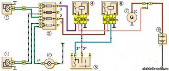
It is worth noting that in the electrical circuit of a scooter, just like in any electronic circuit, there is a common wire. On a scooter, the common wire is the minus (—). In the diagram, the common wire is shown in green. If you look more closely, you will notice that it is connected to all the electrical equipment of the scooter: headlight (16), turn relay (24), instrument panel backlight lamp (15), indicator lamps (20, 36, 22, 17), tachometer (18 ), fuel level sensor (14), horn (31), tail light/brake light (13), start relay (10) and other devices.
First, let's go over the main elements of the Chinese scooter circuit.
Egnition lock.
Ignition switch (12) or “Main switch”. The ignition switch is nothing more than a regular multi-position switch. Even though the ignition switch has 3 positions, the electrical circuit uses only 2.
When the key is in the first position, the red and black wires are connected. In this case, the voltage from the battery enters the electric circuit of the scooter, the scooter is ready to start. The fuel level indicator, tachometer, sound signal, turn relay, and ignition circuit are also ready for operation. They are supplied with power from the battery.
If the ignition switch malfunctions, it can be safely replaced with some kind of switch like a toggle switch. The toggle switch must be powerful enough, because the entire electrical circuit of the scooter is, in fact, switched through the ignition switch. Of course, you can do without a toggle switch if you limit yourself to short-circuiting the red and black wires, as the heroes of Hollywood action films once did
In the other two positions, the black and white wire from the CDI ignition module (1) is shorted to the housing (common wire). In this case, engine operation is blocked. In some scooter models, to block the engine, there is an engine stop button (27), which, like the ignition switch, connects the white-black and green (common, body) wire.
The generator (4) produces alternating electric current to power all current consumers and charge the battery (6).
There are 5 wires coming from the generator. One of them is connected to a common wire (frame). The alternating voltage is removed from the white wire and supplied to the relay regulator for subsequent straightening and stabilization. The yellow wire removes voltage, which is used to power the low/high beam lamp, which is installed in the front fairing of the scooter.
Also in the design of the generator there is a so-called hall sensor. It is not electrically connected to the generator and there are 2 wires coming from it: white-green and red-black. The hall sensor is connected to the CDI ignition module (1).
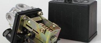
Relay regulator.
Regulator relay (5). People may call it a “stabilizer”, “transistor”, “regulator”, “voltage regulator” or simply “relay”. All these definitions refer to one piece of hardware. This is what the relay regulator looks like.
The relay regulator on Chinese scooters is installed in the front part under a plastic fairing. The relay-regulator itself is attached to the metal base of the scooter in order to reduce the heating of the relay radiator during operation. This is what the relay regulator looks like on a scooter.
Electrical equipment MTZ-80 with a small cabin
The Belarusian tractor MTZ-80 with rear-wheel drive and a small cabin is equipped with DC electrical equipment. All devices are connected “plus” to each other according to the circuit with one wire, the negative terminals “cling” to the ground of the tractor. In the picture you see a color wiring diagram of the old 1974 model.
Let's consider its main elements:
- Battery, generator, relay regulator.
- Electric starter, torch heater and switch.
- Headlights: front and rear, turn signals with turn relays, side lights, brake lights, cabin light, light switches.
- Electric motor of the air conditioning and heating unit.
- Windshield wipers and switches with separate electric motor.
- Measuring instruments. If you did not know how to connect an ammeter to the circuit, then it is already installed between the power source and the generator.
The electrical diagram of the MTZ-82 with a large cabin, shown in the photo, helps the user understand the location of electrical equipment and the cables that connect them. Separate colored callouts decipher the purpose of a particular wire based on the color of the protective insulation.
MTZ-82 tractors with a large cabin of the new generation, which began to be produced in 2010, have some additions to the electrical circuit: a circuit for connecting a radio with the ability to turn on when the engine is not running, as well as an air conditioner with a compressor.
Troubleshooting if turns do not work, even if you do not have special knowledge.
Checking the serviceability of the turn relay.
Turning relay for VAZ 2108
And so, let's look at what to do if the turns of a VAZ with front-wheel drive do not work, except for the 2170 Priora. The operation and troubleshooting of which was discussed in the article “Prior Turning Relay”.
First, make sure that the measuring instruments and control lamps on the instrument panel are working. If they do not work, then check the fuse.
If the devices are working properly, turn on the hazard warning button and check that all the lamps in the direction indicators are blinking. This will allow you to divide the circuit into two parts and speed up troubleshooting.
If the alarm does not work when turned on, then it is necessary to check the serviceability of the turn and alarm relay and the presence of power at its terminal 49. The pin designation is marked on the bottom of the relay, next to the contact legs.
We remove the relay, which is marked in the form of a triangle on the top of the case, from the mounting block, and in the vacated socket, using a test paw, check for the presence of a plus on pin 49. We connect the test lamp to the ground or minus of the battery, and with the other end we touch pin 49, when If the hazard warning button is on, you do not need to turn on the ignition. Lack of power indicates a faulty fuse, alarm button or broken wires, contact tracks of the mounting block and poor contact in the connectors.
If there is a plus on the terminal, then connect terminals 49 and 49A with a copper wire. If the connecting wires and connectors are in good condition, all the direction indicator lamps should light up. This indicates that the turn signal and light signaling relay is faulty. If the lamps do not light up, but there is a plus on pin 49, then there may be a short circuit in the signal lamp circuit and the fuse has blown. A short circuit can also cause the relay to fail. In this case, check the serviceability of the fuse, and if it blows, eliminate the short circuit in the signal lamp circuit.
Checking the hazard warning button.
If the hazard warning lights are working, then the turn signal and hazard warning relays are working properly, but the fault may be in the hazard warning light button. First, check the plus, as described earlier at pin 49 of the relay, with the hazard warning button off and the ignition on.
If there is no plus, then you need to check the serviceability of the alarm button. To do this, you need to remove the button from the socket by prying it off with a thin screwdriver or remove the instrument panel visor. In the contact connector of the button, use a test lamp to check the presence of power at pin 2 (the numbering of pins on the button near the contacts) with the ignition on. If there is no power, repair the broken wire from the instrument panel to the button. If there is power, connect pin 2 to pin 5 in the button socket, with the ignition on, and turn on the direction indicators of either side. If the warning lights on this board light up, replace the faulty hazard warning button.
If the warning lights do not light up, then, without removing the jumper from the hazard warning button block, connect pins 49 and 49A with a copper wire in the relay socket, then check the power at pin 49A of the turn switch. To do this, remove the steering column cover and the connecting connector from the turn switch. You can also remove the switch itself to determine the pin numbers that are marked on its lower part next to the contact legs. This is not difficult to do by squeezing the latches on the sides of the switch and pulling it to the side. If the circuit from the relay to the switch is in good condition, the indicator lamp will start to light. If the control lamp does not light, then repair the break in the wire from the mounting block to the turn signal connector.
Starter in the tractor electrical circuit
A mandatory element of the electrical equipment of Minsk tractors is a starter, which is activated by a color scheme. The starter consists of the following elements:
- Electrical engine;
- drive unit;
- relay;
- switch.
Engine power is 4.8 hp. The MTZ-82 electrical circuit ensures the operation of a starter DC motor, which is made of series excitation coils. All coils have 4 poles.
To turn on the starter, the developers installed a special switch. It is located on the control panel in the operator's cab. The engine starts due to the fact that power comes from the battery. The torque from the shaft is gradually transmitted to the crankshaft, which is associated with the operation of the drive gear with the flywheel.
How to connect to MTZ-80
The Belarus MTZ-80 tractor is equipped by default with a PD-10U gasoline starter, popularly called a “starter”. It has a significant disadvantage - the constant need for fuel. To connect an electric starter instead of a starter, you need to purchase the starter itself, the rear adapter sheet and the flywheel (or flywheel crown).
Before starting work on the replacement, study the electrical diagrams and drawings. The presented diagram shows that to connect, it is enough to connect the wire from the relay to the “plus” of the starter, and the negative terminal to the tractor body.
Turn signal relay pinout
The location of the PC57 relay pins is shown in the figure. 12 volts are supplied to terminal B from the vehicle's electrical system, and the signal to the lamps is removed from the SL terminal. A control lamp is connected to the CL terminal.
On the PC950, pin markings are applied directly to the body. Sometimes, due to a layer of dust or dirt, the symbols cannot be read. In this case, you need to wipe the body of the device.
Modern turn signal relays may have different pin locations, but manufacturers still strive for a single standard (with varying degrees of success). For such devices, it is better to check the pinout in reference books.
According to the results of one of the surveys conducted by the State Traffic Safety Inspectorate, the cause of about 20% of accidents was failure to give turn signals . Maintaining turn signals in good condition and using them in cases stipulated by traffic regulations will reduce the likelihood of an accident by approximately the specified figure.
Expert opinion
It-Technology, Electrical power and electronics specialist
Ask questions to the “Specialist for modernization of energy generation systems”
Starter control system The advantage of a gasoline device is its unpretentiousness, the ability to use low-quality fuel for operation, which does not affect performance at all. Ask, I'm in touch!
Connection diagram for generator MTZ-80
The generator on the Belarus MTZ-80 is installed as a three-phase one, in the rectifier of which the alternating current is converted into direct current. It serves as an additional source of electricity, along with batteries.
The colored electrical circuit of the generator shown in the picture with a description consists of:
- series-installed coils and stator field windings;
- rectifier unit consisting of a diode bridge;
- regulator unit with voltage switch.
Design and principle of operation, repair and maintenance
The Minsk Tractor Plant produces agricultural machinery that is known far beyond the borders of Belarus. For example, bearings are not repaired at all. The PS A socket is located on the rear wall of the operator's cabin and has 7 contacts.
The wires have different colors for ease of finding them in the bundle. Electrical equipment products are produced in climatic versions: U for temperate climates, KhL for cold climates, T for tropical climates, and O general climatic versions.
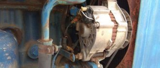
GAZ and 3IL with diesel Typical malfunctions of alternating current generators: Covers: contamination and wear of oil seals and bearings, bearing seats, deformation of steel sealing washers of bearing units, thread failure. The generator is located on a bracket on the right side of the diesel engine and is driven from the crankshaft via a belt drive.
The power supply system includes a generator set and a battery.
Three diodes of reverse polarity are pressed into the housing, and three diodes of direct polarity are pressed into a heat sink isolated from the housing.
Transistor G is open. Restoring the electrical wiring of the MTZ tractor
See also: What is the meaning of kun for a tractor?
Ignition switch MTZ-82 wiring diagram
The ignition switch block is installed on the dashboard and is used to start the starter of the tractor starting engine. Starts or interrupts the operation of a current-carrying circuit. Main parts of the ignition switch 2:
- a switch on which the output terminals and the main contact with the generator rotor are located;
- a lock, which in turn consists of a zinc body, retaining rings, locking cylinders and a key.
The wires must be connected according to the color diagram.
Zzzloj › Blog › Adaptation of turn relays for LEDs.
It all started when a friend and I decided to tune the headlights on his car. Seryoga wanted xenon lenses, and I convinced him to also get angel eyes... In the end, they also decided to make LED turn signals. They did everything for a long time and tediously) But they finally did it. And now we need to solve a couple more issues... one of which is the turn signal relay. And so to the point!
We disassembled the relay. There's a circuit that switches the relay. It is based on a specialized U643B controller from Atmel. As it turned out, many relays are produced precisely on the basis of this microcircuit or its analogues.
The controller has the function of signaling a malfunction of the direction indicator lamps. It detects a malfunction very simply - based on the current in the circuit. If the lamp burns out, the current decreases and the turn signal switching frequency increases.
The value of the current flowing through the direction indicator circuit is recorded by pin 7 of the microcircuit, which is called Lamp failure detection.
As you know, the efficiency of LEDs is much higher than that of incandescent lamps. Accordingly, they consume less current. Therefore, the installation of LED bulbs in turns is perceived as a malfunction in the circuit, and the turn signal relay increases the switching frequency.
The malfunction is detected by the voltage drop across resistor R3. If insufficient power is released on it, the controller will go into emergency mode) Therefore, for normal operation of LED lamps in turns, you need to increase the resistance of this resistor so that the same voltage is released on it as for conventional incandescent lamps.
There are two ways to solve this problem: cut the current measurement circuit (pin 7) or select the resistance of resistor R3 and replace it. The first option is more accessible) although the second is more correct. For now, let's take the path of "least resistance", arm ourselves with a scalpel and cut the conductor on the relay board!
You need to cut here! It is advisable to insulate the incision site, for example with nail polish.
The result did not completely satisfy us. Seryoga thinks that the turn signals work too quickly. You can slow down the process by changing the values of the elements of the reference circuit of the pulse generator R1 C1.
We decided not to bother with the R3 shunt. There the resistance is very small, without precise instruments it’s impossible to find one. So we'll tinker with R1. It will be easier with resistors than with conductors.
As standard, a 91KΩ resistor is installed in the relay. We purchased a multi-turn resistor with a nominal value of 100K and soldered it in place of the original one. Then we connected the relay to the power supply, attached a light bulb to the contacts and rotated the resistor until the switching frequency became satisfactory!
The multi-turn tuning resistor has three flexible terminals. The extreme ones are the resistance itself (resistor), and the middle terminal is a slider. One of the outer terminals can be cut off. In place of the standard resistor, we solder the middle and one of the outer terminals of the new trimming resistor into the board.
In the photo, the resistor in the upper right corner is blue.
Source
Charging circuit MTZ-80
This color diagram with a description shows what elements the charging system of the MTZ-80 tractor consists of.
- Generator, which is the main power source.
- Rechargeable lead-acid batteries act as a backup power source for the tractor engine.
- An indication lamp that lights up when the generator does not produce electric current when the ignition switch is turned on.
- A fuse box that protects an electrical circuit from a short circuit.
The generator and battery are connected with a “positive” wire, and the “minus” wire is output to the metal case.
Purpose of the turn relay
The Traffic Rules in force in Russia clearly state that when making maneuvers, it is necessary to turn on the direction indicators, and in their absence, indicate the direction of movement with your hand. However, now most cars and motorcycles are equipped with turn signals, so you rarely need to use your hands to indicate the direction of travel.
Periodic turning on and off (that is, the same blinking) of the direction indicator lamps is realized using a simple device that is part of the vehicle's electrical system - a turn relay, which is often simply called a breaker or breaker relay.
The breaker relay included in the turn signal circuit performs three functions at once:
- Supplying electric current to the direction indicator lamps (that is, turning on the “turn signals”);
- Ensuring intermittent operation of the direction indicator lamps (their blinking);
- Creation of characteristic clicks, signaling to the driver of the car that the direction indicators are working.
In cars of the Volzhsky Automobile Plant of various generations and models, several types of turn relays are used, which have different operating principles and characteristics.
Turn relay VAZ-2108,2110,GAZ-31105,GAZelle Next AVAR
Turn relay VAZ-2104,05,07,GAZ-3110;3302 AVAR
Turn relay VAZ-2108-10, M-2141 AUTO RELAY
Turn relay VAZ-2101-03 AVTOPRIBOR
Turn relay VAZ-2104-07 AENK-K
Turn relay VAZ-2104,05,06,07 4-pin. AUTOPRIBOR
Turn relay VAZ-2108,2110 EM
Electrical circuit maintenance
Maintenance of the tractor circuit can be done with your own hands or with the help of an electrician. The main thing is that this happens regularly and that all terminals and fastenings are checked. If necessary, it is necessary to clean the necessary parts from dirt and dust.
The starter requires cleaning every 3000 hours of use. To do this you need to do the following:
- dismantle the starter;
- remove dirt;
- remove the casing that performs protective functions;
- check the brush-commutator assembly.
Then the starter must be reassembled and the insulation on the wires, the connections on the plugs, and the integrity of the wires checked.
Source
Turn relays, both for lamps and LEDs, diagram - DIY for cars
It often happens that there is no electromagnetic relay nearby, but there is a need to adjust headlights, turn signal lamps, and the like. To make this possible, a schematic representation of an electronic relay has been developed that is easy to use, convenient and practically uninterrupted. In most cases, it is possible to see similar circuits that are united by one factor: the use of PWM controllers. Thanks to this, high precision in their operation is achieved.
However, let's look at a schematic diagram that replaces an electromagnetic relay, it will be the easiest to use.
The maximum power for the load in the circuit is 150 watts. Its connection occurs in the area of the positive terminal break. If you replace the IRFZ44 series (field key) with the IRF3205, then the ability to connect 200 Watts is achieved.
At first glance, the scheme is simple, but it works quite accurately. In addition, there is no change in the lamp blinking intervals throughout the entire operation. Also, the frequency of its blinking is not related to the power of the lamp itself. This allows you to connect halogen lamps, LED lamps and high-power lamps to the circuit.
The capacitance of the capacitor and the blinking interval of the lamps are directly related. If you increase the capacitance of capacitor C2, then the blinking of the lamp will become infrequent. But if you reduce it, the blinking will speed up. The 1n4148 diode, which has low power, can be replaced with any available diode.
If the circuit reaches 80 watts, a small amount of heat will be generated in the FET area. Now the circuit based on the field effect transistor can be used. It can even be installed in place of the old relay, but its operation will be much more reliable.
And I also want to note one point: if you decide to change your car, I recommend taking a closer look at an official Jaguar dealer. Come in and look at these beauties, price, attractiveness, modernity, this car has always been placed only in the first row.