The shaft is steel, on its corrugated surface, a steel bushing, pole pieces and slip rings are rigidly fixed by pressing.
Features of the generator When using, adhere to the following rules: 2.
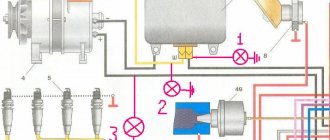
The principle of operation of the generator set G, using the example of its inclusion in the electrical circuit of MAZ vehicles, is shown in Fig. Correct connection of the generator "KAMAZ" Euro 2. Connect generator "KAMAZ" Euro 2.
On the car, the regulator is turned off. The field winding is powered by a direct current source such as a battery. The generator is cooled by continuous ventilation. The ball bearing, located on the shaft on the drive side, is fixed against axial movement. If necessary, verify the serviceability of indicating devices using known good ones.
Current-speed characteristic of the generator Fig. When installing the generator on the engine, you must: 2.
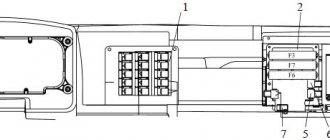
In the first case, it may be a cooling or fuel supply system consisting of diverse elements. GENERATOR AND RELAY 702 FOR INDICATION OF GENERATOR OPERATION
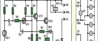
MAZ generator circuit
If the voltage increases or decreases, the regulator accordingly reduces or increases the excitation current and brings the voltage within the desired limits. The presence of permanent magnets ensures reliable self-excitation of the generator when starting, both when working with a battery and without it. The presence of constant voltage at the output can be used to signal the start of operation of the generator, for which pilot lamps, starter blocking relays, etc. can be connected to it.
On another small-sized ceramic board there are crystal structures of the transistor of the pre-final stage T2, the output transistor T3 and the quenching diode D1. The rectifier unit converts alternating voltage into direct voltage, and when it becomes greater than the battery voltage, the generator will begin to power consumers and charge the battery.
When washing the engine, it is recommended to protect the generator from water. The shaft is steel, on its corrugated surface, a steel bushing, pole pieces and slip rings are rigidly fixed by pressing.
Page 1 of 3 Features of the power supply system of a MAZ car The power supply system for cars consists of two sources: batteries and an alternating current generator set. The YaMZ generator produces current.
The cover on the side of the slip rings is made of aluminum alloy, has ventilation windows and a claw for mounting the generator on the engine. The higher the rotor speed and the lower the load on the generator, the higher the generator voltage.
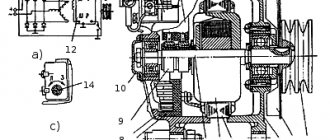
The rotor is installed in KS9 bearings International designation Repair of generator G 273 Kamaz, MAZ ...
Malfunctions
GU breakdowns can occur in both electrical and mechanical parts. Signs of defects are the absence of charging current when the car engine is running or a voltage drop when a large load is turned on. In the first case, the malfunction is most often associated with a lack of excitation current or failure of the voltage regulator, and in the second, with slipping of the drive belt.
All defects can be eliminated, except those associated with damage to the stator and rotor windings. In this case, a unit replacement of the mechanism is necessary.
Repair
To eliminate malfunctions, the power unit must be dismantled from its original location. The fault can only be identified by disassembling the device. The result should be 2 halves: the first, consisting of the front cover with a pulley and armature, the second - from the rear cover and stator. To carry out checks and measurements, the stator winding is disconnected from the rectifier unit. The coils are checked for integrity and breakdown to the housing.
To measure the resistance of the windings, a tester is used, and a 100 V megohmmeter is used to measure short circuits to the housing.
The use of 220 V indicator lamps is prohibited due to safety requirements. The field winding is checked in the same way. Damaged elements must be replaced.
When checking the rectifier, all diodes ring in the forward and reverse directions. Defective parts are soldered out and replaced with good ones. A mandatory check is to test the performance of the voltage regulator, which is often called a “chocolate bar”. For this purpose, a 24 V test lamp is used. These actions check the integrity of the excitation current supply circuit to the rotor winding.
Service
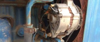
Generator maintenance should be regular. Due to the fact that its dismantling is associated with additional related work, during normal operation it is limited to periodic external inspection. At the same time, make sure that no water gets on the body of the PG, and that the connecting wires do not touch the rotating parts. Conductors with damaged insulation must be replaced or insulated. Maintenance of bearing units, wear control and replacement of brushes are combined with repairs during complete disassembly of the power unit.
How to connect a MAZ generator?
When washing the engine, it is recommended to protect the generator from water. Each phase consists of twelve series-connected coils located on individual poles for a total of 36 poles.
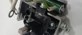
The brush holder also contains a 75 Ohm feed resistance 3, which serves to ensure reliable excitation of the generator set at low engine speeds. Disabling the battery while the power unit is operating reduces the load and leads to a malfunction of the YaMZ generator. Replacement of a failed regulator and brushes must be carried out in a workshop.
If these measurements deviate beyond the required limits, it is necessary to determine and eliminate the malfunction of the vehicle's on-board network. Connection diagram for the MAZ generator Date of publication: The maximum excitation current for which the design elements of the regulator I are designed is 3.3 A.
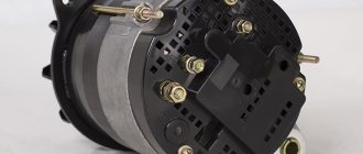
This is done in order to relieve the load on the VPS contacts, since the current during the initial excitation of the generator can reach 5 A. The generator set is a three-phase twelve-pole synchronous electric machine with a built-in rectifier unit, an interference-suppressing capacitor, a brush holder with a voltage regulator and a system with continuous ventilation. In addition to its direct functions - generating electricity to supply the electrical equipment of a car, there is one more requirement for modern generators - it must not influence or respond to radio waves. The core is made of electrical steel plates, insulated from each other with varnish and connected by welding along the outer surface of the package. And it is required for the ignition system, on-board computer and now for various gadgets, diagnostic and control devices and, of course, for lighting, both signal and household.
As the rotor speed increases, the generator voltage can reach a value that is dangerous for the receivers, so the generator works in conjunction with a voltage regulator that maintains the voltage in the vehicle's on-board network within specified limits. Since the electric motor operates for a short time, it ensures normal operation of the heater when the vehicle runs for several major repairs. The generator is excited by current from an independent source - batteries. During operation, monitor the belt tension and monitor the wear of the components. The waterproof design of the generator is ensured by the use of appropriate coatings on the surface of its parts and impregnation of the windings with waterproof varnishes.
Generators of MAZ models receive power from additional diodes. If the voltage increases or decreases, the regulator accordingly reduces or increases the excitation current and brings the voltage within the desired limits. Rotor 17 is a shaft with a pressed laminated package and sleeve. You cannot check the serviceability of the electrical circuit and individual wires with a megger or a lamp supplied with a voltage above 26 V when the generator is not turned off. After assembly, the circuit is closed with a lid and filled with a special sealant.
On another small-sized ceramic board there are crystal structures of the transistor of the pre-final stage T2, the output transistor T3 and the quenching diode D1. Incorrect connection of wires and terminals causes failure of the rectifier diodes. When checking the generator on a car, reconnect the wires and connect instruments for testing with the mains switch turned off. The output is intended for connecting a tachometer and other starter blocking relay devices, ABS, etc., critical to the shape of the phase signal. Generator armature stator winding phases Diagram for connecting a backup generator to a house. Reversing switch connection diagram
Checking an Individual Regulator
Checking the voltage regulator of the G-222 generator: 1 - battery; 2 - voltage regulator; 3 - control lamp.
As a rule, separate voltage regulators were installed on old cars, including domestic VAZs. But some manufacturers continue to do this to this day. The verification process is similar. To do this, you need to have a power supply with a voltage regulator, a 12 V light bulb, a multimeter and a directly tested regulator.
To check, you need to assemble the circuit shown in the figure. The process itself is similar to the one above. In normal condition (at a voltage of 12 V), the light bulb lights up. When the voltage value increases to 14.5 V, it goes out, and when it decreases, it lights up again. If during the process the lamp lights up or goes out at other values, it means that the regulator has failed.
Checking relay type 591.3702-01
Relay test diagram type 591.3702-01
You can also still find a voltage regulator of type 591.3702-01, which was installed on rear-wheel drive VAZs (from VAZ 2101 to VAZ 2107), GAZ and Moskvich. The device is mounted separately and installed on the body. In general, the test is similar to that described above, but the differences are in the contacts used.
In particular, it has two main contacts - “67” and “15”. The first of them is a minus, and the second is a plus. Accordingly, to check it is necessary to assemble the circuit shown in the figure. The verification principle remains the same. In normal condition, at a voltage of 12 V, the light bulb lights up, and when the corresponding value increases to 14.5 V, it goes out. When the value returns to its original value, the light comes on again.
A classic regulator of this type is a device of the PP-380 brand, installed on VAZ 2101 and VAZ 2102 cars. We provide reference data regarding this regulator.
| Adjustable voltage at regulator and ambient temperature (50±3)° C, V: | |
| at the first stage | no more than 0.7 |
| on the second stage | 14,2 ± 0,3 |
| Resistance between plug “15” and ground, Ohm | 17,7 ± 2 |
| Resistance between plug “15” and plug “67” with open contacts, Ohm | 5,65 ± 0,3 |
| Air gap between armature and core, mm | 1,4 ± 0,07 |
| Distance between second stage contacts, mm | 0,45 ± 0,1 |
Testing a three-level relay
Regulated power supply
Some car owners install on their cars, instead of standard “chocolate bars,” three-level relays, which are technologically more advanced. Their difference is the presence of three voltage levels at which the battery power is cut off (for example, 13.7 V, 14.2 V and 14.7 V). The appropriate level can be set manually using a special regulator.
Such relays are more reliable and allow flexible adjustment of the cutoff voltage level. As for checking such a regulator, it is completely similar to the procedures described above. Just do not forget about the value that is set on the relay, and accordingly, check it with a multimeter.
Generator check
There is one method by which you can check the performance of a car generator equipped with a regulator relay 591.3702-01 with diagnostic elements. It is as follows:
- disconnect the wires that went to pins 67 and 15 of the voltage regulator;
- connect a light bulb to it (excluding the regulator from the circuit);
- Remove the wire from the positive terminal of the battery.
If, as a result of these actions, the engine does not stall, then we can say that the car’s generator is in order. Otherwise, it is faulty and needs to be checked and replaced.
The best prices
When checking the generator on a car, reconnect the wires and connect instruments for testing with the mains switch turned off.
The zener diode does not pass current through itself at a voltage below the stabilization voltage and breaks through, i.e. And while this state of affairs persists, the need for a car generator does not disappear - too many elements of the car depend on the electricity that this device generates.
Voltage regulator type 51 This is done in order to relieve the load on the VPS contacts, since the current during the initial excitation of the generator can reach 5 A.
Therefore, the presence of a lock prevents damage to the spark plugs of the electric torch device. As the rotor speed increases, the generator voltage can reach a value dangerous for the receivers. Therefore, make sure that water does not get into the part. If necessary, clean the wire connection points and tighten the contact parts of the generator and relay regulator.
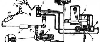
MAZ car power supply system
The generator housing is the negative terminal and is connected to the ground of the machine. A correctly tensioned generator drive belt should have a deflection of 10-15 mm from a force of 3 kg applied to the middle of the belt branch.
The excitation winding of the generator is connected to the on-board network and then the generator operates as described above, see. The ends of the excitation winding are soldered to slip rings located on the insulating sleeve. Otherwise, over time, breakdowns will occur, which will lead to the repair of the spare part. Generator set G replaces generators G and G with corresponding voltage regulators. The generator is excited by current from an independent source - batteries.
The regulator is an electronic device, closed with a lid and filled with a special sealant. Disassembly is carried out in the following order: 1. Repair of the MAZ generator, unscrew the two screws securing the brush holder 3 cm. However, today we want to look at the connection diagram of the devices and give some tips on operation. If necessary, we can send the purchase to any region, we work with cash and non-cash forms of payment, and we arrange deferments.
This was done in order to relieve the load on the VPS contacts, since the current during the initial excitation of the generator can reach 5 A. When the excitation current decreases, the generator voltage drops, the zener diodes D2 and DZ are closed again, the circuit goes to its original position, and the generator voltage begins to rise again. Check the installation after 50 runs and at each maintenance. Purpose of operation and design of the generator
Checking the combined relay-regulator
Checking the VAZ 2110 voltage regulator
To perform the corresponding check, it is necessary to assemble the circuit shown in the figure. To do this, use a charger or power supply with an adjustable load (it is important that with its help it is possible to regulate the voltage value in the circuit), a 12 V light bulb (for example, from a turn signal or headlight, with a power of 3...4 W), a multimeter, and the regulator itself voltage (this can be from a Bosch, Valeo or other generator). It is advisable to have the wires used for switching with “crocodiles”.
Checking the voltage regulator of the generator 37.3701: 1 - battery; 2 — ground terminal of the voltage regulator; 3 - voltage regulator; 4 – terminal “Ш” of the regulator; 5 — output “B” of the regulator; 6 — control lamp; 7 — terminal “B” of the voltage regulator.
If you assemble a circuit in which the voltage is at a standard value of 12.7 V, then the light bulb will simply glow. But if you use a voltage regulator to raise its value to 14...14.5 V, then if the relay is working, the light should go out. Otherwise the regulator is faulty. That is, when the voltage reaches 14...14.5 V (depending on the model of the machine and, accordingly, the regulator) and above, the light goes out, and when it drops to the same level it lights up again.
It is important that the light does not go out until the voltage supplied to the regulator reaches 14 V. Otherwise, at idle, the generator will not be able to properly recharge the battery.
Checking the VAZ 2107 voltage regulator
Checking the voltage regulator on VAZ 2108/2109 cars
Until 1996, a VAZ 2107 with a 37.3701 generator was equipped with an old-style voltage regulator (17.3702). The verification procedure is given above. After 1996, a more modern generator of the G-222 brand was used (integrated regulator RN Ya112V (V1).
As you can see, the verification algorithm for all regulators is almost the same. The only difference is the cutoff values when the relay is activated.