The transmission of the MTZ 82 tractor with all-wheel drive chassis is distinguished by a gearbox that provides additional torque distribution for driving the front axle. The unit is attached by its body to the right hatch of the tractor gearbox housing and is called a transfer case. The mechanism can supply power to the FDA in automatic and forced modes with the ability to completely disable the front axle drive.
Front axle drive MTZ 82
Transfer case (transfer case) of the MTZ 82 tractor - diagram and repair
» MTZ 82 transmission » Transfer case (transfer case) of the MTZ 82 tractor - diagram and repair
The transfer case of the MTZ 82 tractor is used to transmit torque to the front drive axle from the gearbox. Its use allows automatic or forced switching on and off of the front axle. The transfer case ratio is 0.866.
Device
The transfer case is made in the form of a single-stage gear reducer with a one-way roller freewheel clutch and a mechanism that has the ability to turn off, turn on and block the freewheel. The transfer case is located in a separate housing, which is mounted on two pins and bolted to the gearbox hatch on the right side.
The transfer case gear is permanently meshed with an intermediate gear, which is mounted on an axle in the transmission housing and is constantly in connection with the transmission output shaft gear. In this regard, the transfer case gear synchronously activates the front axle in all gears when the freewheel is activated or when it is forcibly blocked by the tractor driver.
The transfer case gear is a single unit with the outer drive race of the freewheel and the internal ring gear for forced locking. Eight jamming rollers, spring-loaded with pins, are located in the profile grooves of this gear. Springs and pins are inserted into the gear holes and secured in them with plugs.
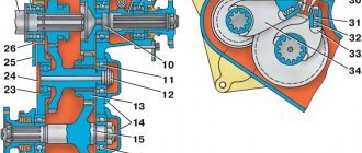
Transfer case diagram of the MTZ 82 tractor: 1 - intermediate gear; 2 — intermediate gear bearings; 3 — secondary shaft gear; 4 - axis; 5 - nut; 6 — driven cage of the freewheel; 7 — roller spring; 8 — pin; 9 — roller; 10 - gear; 11 — gear coupling; 12 — connecting flange; 13 - fork; 14— body; 15 — tension spring; 16 - shaft; 17 — freewheel bearings; 18 - threaded coupling; 19 — thrust stop; 20 - stand; 21 — control rod.
The internal driven race of the freewheel is mounted on the MTZ 82 transfer case shaft on a brass tube and has the ability to rotate relative to the shaft itself.
The inner driven race is provided with an internal crown, by means of which it can be connected to a gear coupling movably mounted on the splines of the transfer case shaft. The outer gear has the ability to rotate relative to the inner race on bearings.
The gear ratios of the rear and front axles, as well as their tire rolling radii, are selected in such a way that, in the absence of slipping of the rear wheels, the gear with the outer race of the freewheels rotates approximately 5% slower, receiving rotation from the gearbox, than the inner race, receiving rotation from the drive front wheels.
Layout of parts in the transfer case: 1 - nut; 2 - flange; 3 - cuff; 4 — body; 5 - gasket; 6, 14, 22, 26, 29, 33 — bearings; 7 - shaft; 8 — lever; 9, 18 — springs; 10 - stand; 11, 12 — thrust; 13 — transfer case housing; 15 — washer; 16 - cover; 17 — pin; 19 - plug; 20 — roller; 21, 25 — bushings; 23, 28, 34 — rings; 24 - screw; 27, 31 — gears; 30 - axis; 32 — clip; 35 - coupling; 36 - fork; 37 - roller with lever.
When the MTZ 82 tractor moves in this manner, its front wheels operate in a driven mode, the rollers are wedged and do not block the independent rotation of the holder and gear. If the rear wheels slip, the speed of rotation of the drive and front wheels slows down, which leads to a decrease in the speed of the holder. At an equal number of revolutions of the cage and gear, the rollers jam, creating one whole of the cage and gear, thereby automatically connecting the front axle to the driving mode.
The operating mode with automatic connection of the front axle is considered the main one. Forced engagement of the front axle is used when reversing, as well as when the tractor is slipping for a long time, for example, when plowing.
If the front axle is forcibly connected, then the action of the brakes on the rear wheels also affects the front ones. In this regard, to improve braking on steep slopes and slippery roads, it is recommended to use forced engagement of the front axle.
On good roads, especially when performing transport work and when moving attached equipment, it is necessary to disable the front axle. This will reduce fuel consumption and tire wear, and also extend the life of the drive and freewheel. The transfer case is controlled using a gear clutch, which, moving on the shaft splines, can occupy three fixed positions: the freewheel is on, off and blocked. The gear coupling is controlled by a rod, the handle of which is located in the cabin. The force from the thrust is transmitted to an external lever mounted on the rotary shaft. The internal lever is welded to the shaft and turns the fork, which fits into the annular groove of the gear coupling and moves it to the required position.
Operating modes
On an ongoing basis, on dirt roads in rural areas, they use the automatic mode of operation of the front axle. To reduce the wear of assembly parts in field work conditions as part of land-cultivating units - plowing, cultivation, it is advisable to use the forced operating mode of the FDA. In conditions of constant driving on roads with hard, dry surfaces, it is recommended to disable the front axle drive.
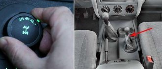
Front axle control
The control lever is located on the right side of the driver's seat and is connected to a rod passing through the cabin floor. The control handle has three positions:
- medium - automatic mode is enabled
- lower - front axle is turned off
- upper — FDA is engaged in forced mode
In later versions of the tractor, control is carried out by a lever, in older versions by changing the position of the handle.
Automatic switching on
In automatic mode, the transfer case transmits rotation only when slipping of the rear drive wheels occurs. In this case, by selecting the position of the control lever, the block sliding along the shaft splines engages its smaller ring gear only with the driven race of the overrunning clutch. This ensures that both parts of the overrunning clutch rotate independently in the unlocked position. The power transmission is switched on due to the jamming of the rollers in the grooves and the connection of both cages when the speed of rotation of the driven cage of the mechanism slows down relative to the speed of the constantly rotating driving part of the transfer case clutch.
The device of the transfer case of the MTZ-82 tractor
The front drive axle is driven from the gearbox through the transfer case of the MTZ-82 tractor and a series-connected intermediate cardan shaft, an intermediate support with a safety clutch and a front cardan shaft. Both shafts are interchangeable.
The transfer case (transfer case) is used to transmit torque from the gearbox to the front drive axle.
With its help, the front axle is automatically or forcedly turned on and off. The transfer case ratio is 0.866.
The transfer case (Fig. 9) is a single-stage gear reducer with a single-acting roller freewheel and a mechanism that can disengage, engage and lock the freewheel.
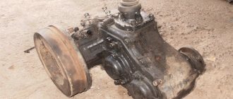
The MTZ-82 transfer case is located in a separate housing 14, which is mounted on two pins and bolted to the gearbox hatch on the right side.
Fig.9. Transfer case MTZ-82
1 — intermediate gear, 2 — intermediate gear bearings; 3 — secondary shaft gear; 4 - axis; 5 - nut; 6 — driven cage of the freewheel; 7 — roller spring; 8 — pin; 9 — roller; 10 - gear; 11 — gear coupling; 12 — connecting flange; 13- fork; 14- building; 15 — tension spring; 16 - shaft; 17 — freewheel bearings; 18-threaded coupling; 19 — thrust stop; 20 - rack, 21 - control rod.
Gear 10 of the tractor transfer case is in constant mesh with intermediate gear 1, which is mounted on axis 4 in the gearbox compartment, and, in turn, is constantly connected to gear 3 of the secondary shaft of the gearbox.
Thanks to this, gear 10 of the MTZ-82 transfer case synchronously engages the front drive axle in all gears when the freewheel is activated or when it is forcibly blocked by the tractor driver.
Gear 10 is made as one piece with the outer drive race of the freewheel and the internal ring gear for forced locking.
In the profile grooves of this gear there are eight jamming rollers 9, spring-loaded with pins 8. Pins 8 and springs 7 are inserted into the drillings of the gear and are locked in them with plugs.
The internal driven race 6 of the freewheel is installed on the transfer case shaft 16 of the MTZ-82 tractor on a brass bushing and can rotate relative to the shaft.
In the cage 6 there is an internal crown, with the help of which it can be connected to the gear coupling 11, movably mounted on the splines of the shaft 16.
The outer gear 10 can rotate relative to the inner race 6 on bearings 17.
The gear ratios of the front and rear axles and the rolling radii of the tractor tires are selected so that in the absence of slipping of the rear wheels, gear 10 with the outer race of the freewheels rotates approximately 5% slower, receiving rotation from the gearbox, than the inner race 6, receiving rotation from the drive front wheels.
When the tractor moves in this way, the front wheels operate in a driven mode, the rollers 9 are wedged and do not interfere with the independent rotation of the gear 10 and the holder 6.
When the rear wheels begin to slip, the rotation speed of the front wheels and the drive slows down, and the speed of the holder 6 decreases accordingly.
Node maintenance
Intermediate support maintenance measures:
- Check the presence of lubricant in the housing at the level of the inspection hole, as well as the lubrication of the cardan joints of the drive every 120 hours of operation
- Check that the assembly is securely tightened
- Check the reliability of the connection of the flanges of the drive shafts with the transfer case, suspension support and final drive of the front axle
- Pay attention to the appearance of lateral play in the bearings of the crosspieces. Timely replacement of crosspiece bearings will prevent serious damage to the drive.
- Based on the nature of the work performed using the front drive axle, pay attention to the moment the support clutch is activated. If necessary, tighten the coupling nut.
The filling volume of the unit is 0.15 liters. The transmission lubricant used for the support is TAp-15V, TSp-10, TSp-15K, TAD-17 GOST 2365-79. For the convenience of filling the unit with lubricant, many practitioners additionally equip the body with a grease dispenser with a spring-loaded shut-off ball valve.
Source
8.1. Transfer case. Malfunctions, disassembly, repair.
Rice. 2.7.1. Transfer case: a - general view; b - relative position of parts; 1 - nut; 2 - flange; 3 - cuff; 4 — body; 5 - gasket; 6, 14, 22, 26, 29, 33 — bearings; 7 - shaft; 8 — lever; 9, 18 — springs; 10 - stand; 11, 12 — thrust; 13 — transfer case housing; 15 — washer; 16 - cover; 17 — pin; 19 - plug; 20 - roller; 21, 25 — bushings; 23, 28, 34 — rings; 24 - screw; 27 31 — gears; 30 - axis; 32 — clip; 35 - coupling; 36 - fork; 37 - roller with lever.
Structure and functions of the transfer case of the MTZ wheeled tractor
The engine is the most important element of any tractor mechanism. It is a device of extraordinary complexity, which includes a huge number of various components and parts. Moreover, each of them performs its own unique functions.
The main distinctive feature of tractor engines is that they can operate in extremely difficult conditions for a long time. At the same time, an engine of this type does not lose its operational parameters and characteristics.
Tractor repair Belarus MTZ-82
One of the most important components of the engine unit is the transfer case. This article is dedicated to her.
How to assemble the gearbox of a MTZ walk-behind tractor
Let's consider gearboxes of other agricultural machinery. The Belarusian machine-building company that produces tractors is constantly improving the assembly of its equipment, equipping it with new devices and accessories. The MTZ-1221 gearbox, the MTZ-320 gearbox, and the MTZ-50 gearbox are similar to the diagram previously discussed for the MTZ-80 and the MTZ-82 gearbox. The gearbox diagrams on all the manufacturer's agricultural machines are not much different. With proper care and proper handling of the equipment, repair of the MTZ-320 gearbox, as well as repair of 82 and 80 models, may simply not be necessary.
Functions performed
The transfer case is an engine element that transmits the torque of the engine unit to various drive mechanisms and distributes it between them. This unit as part of the Belarus tractor performs the following main functions:
- the box distributes the moment of force among the drive axles. This helps to achieve maximum cross-country ability of the tractor, eliminating the formation of a negative process in the transmission called “power circulation”;
- increasing torque on all driving wheels. Thanks to this, the tractor is able to easily overcome steep climbs and resist wheel rolling when driving over difficult terrain;
- creating the ability to move extremely steadily at low speeds combined with maximum torque.
Structure
The transfer case includes the following important elements:
- drive shaft;
- a shaft that controls the operation of the drives of the rear and front axles;
- center differential, which includes a locking mechanism;
- gears: low and chain (gear).
Let us dwell in more detail on the functionality and principles of operation of each node.
The drive shaft transmits torque to the transfer case. This is where the center differential begins its work. It distributes torque among the axles, and is also responsible for ensuring that they rotate continuously regardless of the angular speed mode.
There are two types of center differential: symmetrical and asymmetrical. The functions of the first are to ensure that the torque between the axles is distributed evenly. An asymmetrical differential distributes torque in the required ratio.
The center differential includes a locking mechanism. It helps to fully realize the all-wheel drive capabilities of the MTZ tractor. This happens due to the proposal to partially or completely turn off the differential. The result is a stable two-way connection between the two axles: front and rear. There are two possible locking modes: automatic and manual.
The chain type transmission has the form of a planetary gearbox. Its main task is to enhance torque when traveling over rough terrain. The chain drive includes: drive chain, driven and drive wheels.
The transfer case can include not only a chain drive, but also a gear drive. The main function of the latter is to transmit torque to the front axle. The shafts of the drive and rear axles are located coaxially in relation to each other. In accordance with the current situation, for example, in case of slipping of the front wheels, it is possible to activate the front axle in several modes: automatic, forced on and off.
Common faults and solutions
The most common problems with the transfer case of a Belarus tractor are:
- reducing the elasticity of the clamping springs;
- wear of the rollers, as well as the overrunning clutch;
- failure of the front axle in case of slipping of the rear wheels.
Troubleshooting methods depend on what type of problem a particular breakdown relates to. In the first case, it is enough to replace the faulty parts.
If the rollers or clutch are worn out, you will have to disassemble the tractor transfer case. After this, you need to carefully examine all the parts and identify those that are worn out. Then all available seats are measured. If there are even small defects on the parts, they must be replaced.
The reason for the failure of the front axle is usually the failure of the gear coupling fork or its significant wear. In this case, you must first remove the plug. Then they examine her and measure the thickness of her cheeks. If the inspection reveals any deviation from the specified standards, the plug should be repaired or replaced with a new one.
Causes of support malfunctions
Often, insufficient pressure on the clutch discs provokes operation and slipping at weak forces, which is accompanied by overheating of the unit. The clamping force of the promo-pore cotter pin nut can decrease as a result of natural operating wear of the coupling discs, as well as when the elasticity of the spring disc washers, which exert their force on the coupling discs, decreases. When slipping occurs as a result of friction, the oil boils in the support body and the excess pressure of the expanded heated lubricant squeezes out the sealing seals. After loss of lubrication, the unit begins to run dry, subjecting the structural parts to rapid wear. If the control subsequently ignores the condition of the unit, operation without lubrication can lead to destruction of parts and jamming of the mechanism, as well as emergency breakage of the support housing mounting bracket.