Transfer case UAZ Hunter: Design and switching
- UAZ Hunter transfer case device
- Problems and solutions
- Switching transfer case UAZ Hunter
- Lubricant change
Today it is impossible to imagine off-road vehicles without special equipment; such a mechanism includes the UAZ Hunter transfer case. The device helps the vehicle overcome sections of roads that would seem impassable with a classic configuration. The ability of a vehicle to move on an unpaved surface is achieved by distributing impulse to each drive wheel. As a rule, both axles of the car are involved in this.
The transfer case on the UAZ “Hunter” is an auxiliary mechanism located next to the gearbox. The presence of the unit doubles the number of stages, and a successful combination of gear ratios increases the operational capabilities of the equipment.
Transfer case UAZ “Hunter”:
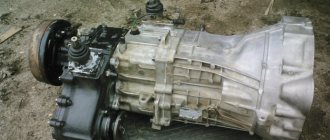
Transfer case for UAZ
You can already write textbooks about the cross-country ability of the UAZ (Ulyanovsk Automobile Plant) bestsellers. The owners of such cars know very well how this is achieved. For those who are just considering the prospect of purchasing a car of this brand or want to understand the reasons for its vulnerabilities, the first thing to do is to find out about the design of its transfer case.
UAZ Hunter transfer case device
The UAZ Hunter single-lever transfer case, the purpose of the product is to distribute the impulse removed from the power unit to the working pairs of wheels. Structurally, the unit is equipped with two stages and a reduced speed. There is no differential between the axles in the design.
The impulse arrives at the transfer case shaft after the classic gearbox. The secondary shaft is in constant contact with the main stage of the pair of wheels behind the car, the connection occurs through a cardan. Activation of the first pair of wheels connects the shafts to each other using a gear coupling, and the parts rotate at equal speeds.
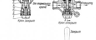
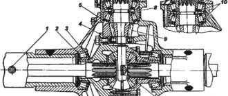
Transfer case diagram:
The design contains a tray made of cast iron and closed with a plug. In addition, the composition includes shafts: main, secondary, middle, front wheel activation shaft; wheels with teeth and clutches that disengage the front wheels.
The transfer case of the UAZ “Hunter” is fixed to the pallet of the classic box with four bolts; a hermetic compound is used to seal the joint. The alignment of the products to each other occurs with the outer part of the bearing of the secondary shaft of the gearbox. The handbrake parts are attached to the rear of the transfer case. The transfer case tray contains the main, middle shafts, activation shafts of the front and rear wheels, the parts are fixed in swing bearings.
The end of the secondary shaft of a classic box with splines cut on the surface is the main shaft of the transfer case, inserted into the main gear of the product. The shaft that activates the rear wheels is mounted on two ball bearings; the part is placed coaxially relative to the main shaft. In addition, in the middle of the shaft there is a gear that activates the speed measurement device. The middle shaft is made together with the gear of the reducing stage; fixation occurs by means of bearings with balls and rollers. The activation part for the front wheels is made together with the gear and is mounted from below in the tray on two bearings with balls.
The transfer case is controlled by two rods and two forks, the location is the transfer case pan plug. Shifting occurs by sliding the forks along fixed rods.
Repairing transfer case: do-it-yourself UAZ car
The transfer case helps distribute the torque from the engine to several drives at the same time.
You can repair the UAZ transfer case yourself; it is not as difficult as it seems at first glance, and you will also be able to save on paying for the services of a car service technician.
Causes of transfer case malfunction
This is the unit
Before starting repairs, of course, it is necessary to find out the cause of the malfunction.
- There was a loud noise in the transfer case. This could be the result of loose nuts that connect the transfer case to the transmission or loose bolts on the bearing caps. The list of reasons includes wear of the bearings or gears themselves, poor-quality or unsuitable oil, or its low level.
- Gear selection and shifting work poorly. This usually occurs due to the clutch seizing on the splines of the front drive hub or shafts. Or, alternatively, the gear selector is deformed.
- The transmission switches off spontaneously while the vehicle is moving. The gear teeth may be worn. Also, shutdown may be affected by an increase in the gap in the spline connection or wear of the clamp parts.
- Oil leaks. Often the problem is caused by wear or mechanical damage to the sealing gaskets, loosening of the nuts on the cover, wear of the seals or sealing rings of the actuator rods.
The solution to all these problems is either repair or replacement of faulty parts. In some cases, it will be enough to just tighten the nuts or add oil.
Stages and main points of repair
Repair of the transfer case takes place in several stages.
- Removing and disassembling the box.
- Troubleshooting.
- Eliminate these faults by replacing the part or repairing it.
- Assembling and installing the box in place.
Disassembling the unit
To remove the box and disassemble the UAZ 469 transfer case, you need to proceed as follows:
- drive the car into the inspection hole;
- lower the parking brake lever and put the gear levers and transfer case in neutral;
- then the casing and lining are unscrewed one by one, the handles and covers are removed, and all wires are disconnected.
Before you start disassembling the device, you need to wash it and drain all the oil. For ease of disassembly, it is better to use a special stand where the transfer case can be secured.
When disassembling the differential, it is advisable to mark on its body the relative positions of the driven gear mounting bolts, so that later it will be easier to put everything back in place.
Finding faulty parts, repairing and replacing them
Before inspection, all parts must be cleaned with a brush and rinsed.
- Oil seals. They are considered unusable if the wear of their working edge exceeds 1 mm. For any minor damage, the part is replaced with a new one.
- Covers and crankcase. Cracks, dents, chips - all this is a good reason to replace it with new parts. However, for very minor damage, you can get by with simply cleaning the damaged area with a file.
- Gears. Worn teeth and their chipping are a reason to replace the part. Otherwise, this will lead to deterioration in handling on difficult road sections and increased load on the engine.
- Shafts. For these devices, the first thing to check for wear is the splines, working surface and threads. By installing the front and rear drive shafts on the prisms and turning them by hand, as well as the drive shaft, we check the runout of the end part, which should not exceed a tenth of a millimeter.
- Bearings. Check for scratches and other damage to the surface. Any cracks or chips indicate the need to replace the bearing. The work of the part must be flawless. It is important that its turns are carried out without jamming or extraneous sounds. Otherwise, the bearing is unusable and must be replaced.
- Clutch and hub. May have nicks, burrs and burrs, which can only be cleaned with a file. If the ends of the teeth on the coupling are damaged or deformed, the part must be replaced.
- Differential. In case of minor damage to the surface of the satellite axis, they can be sanded with fine-grained sandpaper. If the damage is significant, the axle will have to be replaced.
The UAZ transfer case is assembled in the reverse order to the one in which it was disassembled, and before installing the unit in place, its operation is checked on the stand. The function must be flawless, the assembly must be correct, and it is important that no oil leaks. Tests are carried out first in a higher gear, then in a lower gear.
Problems and solutions
The box requires periodic inspection and service. The mechanism is reliable, unpretentious and tenacious, provided it is handled correctly.
| Source of problems | Liquidation |
| Excessive device hum | |
| Weak fastening of the transfer case to the classic box, or loosening of the bearing caps. | Tighten the fasteners. |
| Cardan imbalance. | Adjust or change the product. |
| Bearing removal. | Replace worn bearings. |
| Demolition of gears. | Replace worn gears. |
| Inconsistency in the characteristics of the working fluid. | Replace with recommended fluid. |
| Low lubrication level. | Add fluid to normal level. |
| Difficult switching | |
| High degree of wear on car wheels. | Replace the wheels, set the pressure to normal. |
| Shaft connectors are jammed. | Sand, replace damaged elements. |
| Damage to gear locking devices. | Align or change the device. |
| Transmissions are “flying out” | |
| Gear teeth worn out. | Replace worn gears. |
| The gaps in the longitudinal protrusions of the shaft have been increased. | Provide normal spacing. |
| Demolition of fixing devices, reduction of the force of elastic elements. | Replace worn items. |
| Leakage of working fluid | |
| Seal failure. | Replace seals. |
| Reducing the tightening level of fasteners. | Tighten fasteners. |
| Damage to seals. | Replace sealing elements. |
| Potholes and pores are not on the surface of the frame. | Change the skeleton elements. |
Repair of UAZ “Hunter” gearbox:
IMPORTANT!: Hunter machines use four or five-speed gearboxes. Five-stage devices use a working fluid whose characteristics differ from the lubrication parameters of the transfer case; a mixture of these suspensions is not permissible. The working fluid of the four-speed gearbox and transfer case is identical, you can mix oils.
Switching transfer case UAZ Hunter
The transfer case is controlled and activated from the driver's cab, remotely. To do this, the user uses the levers located on the right side in relation to him. It is noteworthy that the machine, depending on the installed configuration, uses both single-lever and double-lever gearbox control designs.
The inclusion of a lower gear by an activating mechanism with one lever is accompanied by an independent shift of the lever at the end point, under the influence of a spring element, to the left side (towards the driver).
Transfer case shift lever positions:
The procedure for turning off a lower gear is accompanied by a preliminary shift of the lever to the right until it stops (in the direction of travel of the car). After which the lever moves to the zero position, forward in the direction of movement of the machine.
When working with a mechanism that controls the transfer case with two levers, take into account that the top switch drives the front pair of wheels. Device positions: first (wheel set on), second (wheel set off). The transfer case is controlled by three positions: first (main gear is working), second (zero position), third (low gear is activated).
IMPORTANT!: To prevent breakage of the transfer case gear teeth when switching gears, you can activate and deactivate the device (direct and low gear) only after the machine has completely stopped.
What functions does the UAZ transfer case perform?
The UAZ transfer case, also known as the transfer case, is a unit that is responsible for the “distribution” (distribution) of torque to the front and rear axles. Like all all-wheel drive SUVs, cars of this brand by default have 1 drive axle - rear. But they leave the opportunity to distribute the force to the front axle. The distribution box is responsible for this.
It performs 3 main functions:
- torque distribution between the front and rear axles;
- inclusion of a lower gear range, which allows you to increase torque to overcome a serious obstacle (lower gear is not available everywhere);
- locking the center differential.
In simple words, this means that when switching the transfer case to an UAZ, you can achieve improved cross-country ability, optimal controllability and maneuverability. Some transfer case models (including tuned ones) provide not only switching to the front drive shaft (or distributing the load to both axles), but also completely disabling the front axle.
Placement and appearance
The transfer case on all UAZ models, including Hunter and Patriot, and the good old Bukhanka (UAZ-452 transfer case), is installed in the gearbox block. It is connected to the chassis by 2 drive shafts (leading to the front and rear axles, respectively). Center the transfer case on the outer part of the 2-row secondary shaft bearing.
The unit is a mechanical box (cast iron or aluminum), through the cover of which 1 or 2 control levers are led into the passenger compartment (in the gearbox). In new models, the levers are replaced by a flat round switch.
We invite you to watch an interesting video about the UAZ “Hunter” with a reduction of 3.36 in the transfer case:
Lubricant change
A dispensing device is a product whose breakdown occurs extremely rarely, since the mechanism is reliable, simple and technologically advanced. However, the procedure for replacing the working fluid is required to confirm the above.
The plant that produces transfer cases for the UAZ “Hunter” provides for manipulations every 30,000 km. The volume of liquid being poured is 0.7 liters. For filling, transmission lubricant is purchased that meets the criteria: 75W90, class GL-3.
IMPORTANT!: The old oil is drained after completing a trip by car, no later than fifteen minutes from the moment of stopping.
- To carry out the work, take a key to “12”, a container for working;
- Place a container under the transfer case pan drain hole;
- To simplify the procedure, open the oil filler plug;
- Unscrew the drain plug and drain the liquid;
- Wash the plug, remove impurities and metal particles, and reinstall;
- Fill the box with clean lubricant using a syringe and maintaining the desired level;
- Replace the grease filler plug.
Communities › UAZ drivers › Forum › Switching on the front axle hubs from inside the Hunter
Anyone who has dealt with this topic will be glad if you tell me HOW?
I know about automatic HUBS, on some NISSAN TERRANO of the 90s, there is also pneumatic activation on MITSUBISHI PADJERO and SPACEGEAR before 95.
I know that there are such things, I’m interested in HOW to attach them to the UAZ
Buy in a store and screw it on) www.4x4ru.ru/?id=505
Thanks for the information, I didn’t know that automatic machines were made for UAZs!
I didn’t understand how they turned on (I CAME OUT AND TURNED ON MANUALLY) :(. I wanted to know about turning it on with a button from inside the cabin
As far as I know, automatic ones work as follows: I stopped, moved the front axle connection lever forward, drove forward, the hubs automatically engage with the axle shafts - the axle is connected. To disable the bridge: stop, drive back, drive 2-3 meters back, the hubs disengage from the axle shafts, stop and move forward, the bridge is disabled. This is how hubs work on TERRANOSaurs. One BUT! When the node is brought closer, it begins to function poorly. Either one of the hubs does not turn on, or it does not turn off. Many owners of USED TERRANO (right-handed) replaced automatic machines with manual ones.
This is not the only downside. I had these on my Daihatsu Rocky. So, in fact, to turn on the axle, you need to turn on the transfer case to all-wheel drive. After about half a turn of the wheel, the front axle is connected. You can only turn it on when the car is stationary. Which is extremely inconvenient when you drive in winter on either a slippery surface or a hard one. When the hubs are already turned on, you can connect the front axle at speed, but when driving in the city you often need to reverse. Just like when you turn it on, to unlock the hub you need to make the wheel make half a turn, only back in rear-wheel drive mode. This is where another minus arises. If the assault on the hill fails and you need to roll back to try again, the front axle automatically disengages and you start moving again on the rear wheel drive. If the acceleration area is limited, then you get a completely unpleasant feeling. You can only forget about driving in rear-wheel drive, but in low gear you can also forget about it. And this is extremely convenient when you are either jostling in a traffic jam or towing a trailer. It was on this basis that I installed ordinary mechanical ones. Also, the front axle on some cars such as Wrangle, Jimny, Mitsubishi is activated by vacuum, but there is usually a composite axle shaft there. By the way, this option is extremely gentle and very often capricious. Therefore, maybe it’s worth reconsidering your views on automation?
Summary
Summarizing the above, it is worth concluding that the transfer case in modern UAZs is a completely reliable mechanism (both the mechanics and the new version). But it requires good maintenance, without which it can doom the car owner to significant costs.
Do you check the condition of the transfer case before each off-road ride? Tell us exactly how. Maybe your friends know what other features mechanical (old) and chain (new) devices have? Be sure to share this article with experts and beginners so that useful tips and important questions will be added in the comments, which our experts will definitely answer in the following materials.
How the UAZ front axle works: detailed instructions for maintenance and repair
UAZ is a legendary SUV, popular both in Russia and beyond its borders. The car has been produced for quite a long time, which has proven the reliability of its design. This machine is actively used in the army. There are minor differences between the civilian and military versions. However, both here and there the UAZ front axle showed its best side. There are several modifications: on-board, regular, “loaf”, etc. Also, one cannot fail to note one of the advantages of the car - maintainability and the ability to restore the functionality of any unit, even in “garage” conditions. The mechanism allows you to activate all-wheel drive, which helps you confidently overcome obstacles.
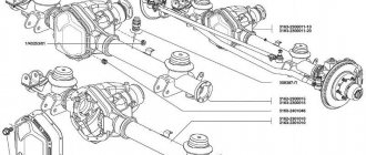
UAZ front axle structure
It consists of a crankcase (sometimes called a stocking), a differential and a final drive. The rear and front axles have no fundamental differences. The only difference is in the direction of the thread of the oil rejection ring located in the main gear. The current design of the UAZ front axle is shown in the picture below. The support placed on the casing is fixed with five hardware. Pin bushings are pressed into the support. A pair of pins “engages” in holding the fist. He also holds the housing cover of the wheel gearboxes. A pin is fixed on it along with a shield on which there are parts of the brake system.
The pins do not rotate in the fist thanks to pin-type stoppers. The fist itself is made with preload (0.02-0.1 mm). The UAZ 469 axle is adjusted using spacers. Location: between the turn lever and the trim (left or right). The spacers are located between the pads and the fist.
One of the features of the described mechanism is that, in addition to increasing cross-country ability, it also turns the wheels. For this purpose, Birnfield ball joints are used. Their cavities contain lubricant that does not need to be replenished throughout their entire service life. The cams, as well as the axis of the pins, are inclined, which allows the wheels to be returned to the middle position after making a turn. The main advantages of the beam (Spicer):
- track is 1.6 m, which has a positive effect on the stability of the car;
- the wheels rotate at an angle of up to 32 degrees, which gives the machine improved maneuverability;
- instead of leaf springs, a dependent suspension on springs is mounted;
- no need to replace lubricant in mechanisms (fists);
- removable cover facilitates access to parts in case of repair;
- the differential together with the gearbox are in one housing - this increases rigidity and service life;
- An improved satellite gear has reduced noise.
Particularly worth mentioning are the hinges, or more precisely the stabilization of angular velocity. This is a design that ensures the stability of rotation of two shafts: the drive and the accompanying. The hinge includes two forks: in their sockets there are 4 balls. In the middle sectors of the parts there is a fifth one, needed for installation operations. In particular, centering the fork. To deactivate the front-wheel drive, there is a special device consisting of a clutch, bolts, and balls.
Distinctive features of the military version
The main feature of the front axle in the military version is the placement of the gearbox. It is located higher. The second distinctive point is the gear ratio - 5.38. The civilian version of UAZ 469, 452, 3151, 3303 has 4.6 or 5.125. All these characteristics increase the distance from the bottom of the car to the road surface from 220 to 300 mm. Those who want to quickly replace an ordinary bridge with a military one will be disappointed: this will not work without alterations. The reason is in the design of the bipod and suspension. In addition, driveshafts differ in length.
Main design problems
It is better to install reinforced axle shafts on UAZ axles
A bridge is a complex structure, the failure of which causes the entire vehicle system to fail. Main malfunctions of the rear and front axles.
- Defective teeth of the main pair.
- Axle shaft defect.
- Oil leak.
- Bearing defect.
- Washer wear.
For what reasons do these malfunctions occur? If the car is equipped with rear-wheel drive and the front axle is connected here, then wild rides on bumpy roads will lead to catastrophic consequences. The transmission fails first, followed by everything else. If you often use gear oil without taking into account the season, then do not expect good performance from your car.
If axial gaps occur in the bearings, all sorts of failures occur, so it is very important to periodically inspect all parts of the car to identify problems. If the pressure in the tires changes frequently, then their long operation will lead to the destruction of parts. Defects in the shaft, crosspieces and suspension bearings also lead to problems.
The main cause of most problems is wear of components or their poor quality. Strong overloads will not have a positive effect on the operation of the parts; still, take care of your car. Insufficient lubricant for parts is another cause of malfunctions. Incorrect adjustment of the front axle bearings will also lead to unpleasant consequences.
Axles from MTZ significantly increase wheel clearance
Tuning is a good thing, but only if it is carried out by real professionals. But quite often, unscrupulous specialists make gross mistakes, as a result of which the stroke and dimensions of the driveshaft completely do not coincide with the required parameters. The result is a serious breakdown and the need for almost major repairs.
Symptoms of structural failure.
- The front axle on the UAZ, like the rear axle, begins to emit a characteristic sound.
- At first the car is almost imperceptible, and then it begins to lose control more and more.
- The driver notices that fuel consumption is higher than before.
- Engine and transmission parts wear out quite quickly.
- Wedge while moving. Note that this is the worst of the symptoms. This means that there is a gap between the bearings, which can lead to serious problems. The wedge is accompanied by noise and crackling. In this case, urgent repairs are necessary.
To prevent malfunctions, timely adjustment of the UAZ rear axle, and the front one too, is necessary.
How to turn on the front axle on a UAZ
To transfer torque to the gearbox, a cardan shaft is used, connected to a transfer gearbox that has a pair of stages. Patriot cars use two types of transfer cases: Russian mechanical or Dynamos, which has an electric drive. The latter option has been in use since 2013. In both options, you cannot do without a clutch for engaging the front axle of the UAZ.
The drive is controlled using a lever or washer located on the central tunnel. To turn on or deactivate the UAZ front axle, you need to:
- Fully depress the clutch;
- Move the lever to the desired position (the modes are indicated on the plastic handle). Carry out the operation at a speed of no more than 60 km/h;
- Release the clutch: you can then drive with the axle activated. To disengage it, depress the clutch again and move the control lever to neutral.
Engaging the axle on SUVs with a Dymos gearbox is much simpler: you need to turn the washer to the desired position. The design of the transmission is such that it is not forbidden to connect the axle directly while driving. However, if a reduced speed is required, you will have to stop.
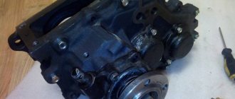
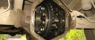
Razdatka UAZ 469
The UAZ 469 transfer case is used in the car to distribute the traction forces of the transmission to the rear bogie and the front drive axle. Transfer cases are only installed in vehicles with all-wheel drive to enable it. The unit is two-stage and doubles the speed range of the machine both when moving forward and backward.
Photo 1: Transfer case UAZ 469 (Source: Yandex.Pictures)
Node purpose
The UAZ 469 transfer case is designed for efficient vehicle driving off-road, rough terrain, and driving on roads without asphalt. When the car overcomes difficult, difficult areas of forest or swampy terrain, reducing torque with the help of the steering wheel significantly reduces the degree of wheel slip.
All car models produced by the Ulyanovsk Automobile Plant are distinguished by an increased degree of cross-country ability, excellent handling, and the ability to overcome any off-road conditions. The RK increases the vehicle’s maneuverability and cross-country ability, allowing you to quickly move on roads of varying quality without any problems. The UAZ transfer case is activated mechanically from inside the car using two levers.
The rear drive axle of the UAZ 469 is constantly on. The front drive axle is connected as needed when the vehicle overcomes obstacles. Driving on good asphalt roads is carried out with the front drive axle disabled. In such conditions, it works like a simple front axle of a car.
IMPORTANT! When driving a UAZ vehicle for a long time on a high-quality road with asphalt or concrete pavement, operating the vehicle with the front drive axle constantly engaged is prohibited. This will lead to breakdown of transfer case components and jamming of rotation parts.
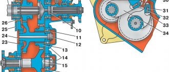
UAZ 469 transfer case
The UAZ 469 transfer case is shown in the bottom figure.
Photo 2: Transfer case structure of UAZ 469 (Source: Yandex.Pictures)
The transfer case is rigidly bolted to the rear of the gearbox housing. A parking brake mechanism is installed on the rear of the transfer case. This device is made in the form of a drum and a block clamp with friction linings.
When the driver needs to apply the parking brake, a clamping device presses the shoes against the drum. This blocks the rotation of the rear axle driveshaft. After releasing the parking brake lever, the pads move in the opposite direction under the action of power springs. Braking of the propeller shaft stops.
Transfer case housing
The transfer case housing for the UAZ 469 car is cast from cast iron. In the plane of the housing there is a connector perpendicular to the axes of the shafts. Two tubular pins determine the relative position of the body halves. The crankcase assembly and cover are processed mechanically. Because of this, they are not individually interchangeable.
There is a hatch on top of the crankcase. It is closed with a lid. If necessary, a power take-off mechanism is installed here. The gearbox is centered on the gearbox along a double-row angular contact bearing through an intermediate cup. Between the two boxes are a suspension plate and sealing gaskets.
Carter RK is assembled from two halves. To prevent the leakage of oil circulating in the cavities of the transfer case during its operation, a sealing gasket is installed between them. In the places where the shafts are installed, which extend outward from the housing, oil seals are placed. They reliably hold lubricants inside the unit while the vehicle is moving.
The operation of the transfer case, gears and shafts is associated with increased loads. When overcoming obstacles, when all mechanisms are involved, metal parts heat up. The oily substance inside the housing evaporates and gases accumulate in the cavities.
In order to avoid depressurization, in order to remove harmful accumulations from the crankcase to the outside, the manufacturer has provided for installing a special breathing valve - a breather - on top of the transfer case housing. This device ensures communication between the internal cavities of the crankcase and the atmosphere.
Maintenance
Maintenance of the UAZ bridge is simple and comes down to monitoring the level of lubricant and topping it up and replacing it. The second point is to check the seals for leaks. It is regularly necessary to check the reliability of the fastenings, especially if the machine is used in difficult road conditions. Eliminate axial play in the differential bearings in a timely manner.
Assembly and connection diagram
When assembling the structure, do not remember several features:
- Press the bushing into the trunnion flush with the end of the washer socket. After completing the procedure, the sleeve must be deployed;
- Place one thrust washer inside the trunnion, the second - in the support. The oil lines in the thrust washers should face the joint. The washer is secured by punching in 3-4 places;
- When installing the hinge, add lubricant to the ball joint;
- Treat the pins and bushings with liquid lubricant.
To obtain the required axial tension, you need to select a certain number of spacers (but not less than five). They are installed on the ends of the knuckle body at the top and bottom. Their number should be the same. Soak the felt ring of the ball joint oil seal with engine oil. If possible, check the bridge on a bench after assembly. If the assembly is done correctly, the axle shafts should not heat up or make excessive noise when braking. Leaks through seals, cuffs, and bolted connections are not allowed.
Repair of the most common faults
Restoring the bridge to operability is not very difficult: but it is required to be careful when performing operations. What “diseases” are most common?
Leak formation
Where the steering knuckle connects to the bridge, there is an oil seal - one of the weak points of the design in terms of lubricant leakage. The oil seal can leak oil not only due to wear, but also when the breather is clogged. If you add more lubricant than required, the result will be the same: a leak. There are two types of oil seals:
- rubber: inexpensive, but also short-lived;
- polyurethane: more expensive, have a long service life.
To replace a part, place the car on a level place and jack up the problem side, loosening the wheel nuts in advance. Further:
- remove the steering knuckle;
- clamp the part in a vice;
- pull out the oil seal by prying it with a flat screwdriver or other suitable tool;
- pull the oil seal out of the support cavity;
- Lubricate the seal before installation;
- press in the oil seal using a tube of the appropriate diameter.
- Installation is in the reverse order.
The mechanism began to hum
First of all, check the oil level. If it is normal, the bridge will have to be removed and disassembled. If the bridge hums constantly in any driving mode, the reasons may be as follows:
- incorrect setting or limiting service life of differential bearings;
- breakage (wear) of the axle shaft (its bearing);
- wear, damage, incorrect gear adjustment.
These bearings simply need to be replaced with new ones. If a humming noise appears during a sudden stop or acceleration, the reasons are as follows:
- incorrect clearance between the final drive gears;
- The final drive gear teeth do not mesh correctly.
In this case, you need to correctly adjust the gearing or replace defective parts. If the bridge hums when the UAZ enters a turn and moves in a straight line, the reasons may be the following:
- satellites rotate with great effort;
- abnormal operation of the axle gears in the differential;
- destruction, severe wear of the axle bearing;
- incorrect clearance between gears located in the differential.
To restore the functionality of the mechanism, adjust the clearances correctly and replace damaged, worn bearings. It is worth noting that the desired result when adjusting the gaps can only be achieved on a bench.
Wheel axial play
It occurs when the wheel bearings are incorrectly adjusted or when they completely fail, which is caused by over-tightening. As a result, the bearings become very hot, the smear liquefies and flows out. Algorithm of actions when performing the correct adjustment:
- Jack up the wheel on the desired side;
- Use a puller to remove the axle shaft;
- Move the lock washer to the side and unscrew the lock nut;
- Spin the wheel: if it rotates tightly, the reason may lie in jamming of the cuffs, contact of the drum and pads, etc.;
- Tighten the adjusting nut. Do this gradually while spinning the wheel. Use the WRENCH;
- Unscrew the nut about a third of a turn and install the lock washer. Tighten the nut and lock it;
- Check how the wheel rotates: it should spin freely without sticking;
- Replace the axle shaft, replace the bolts and tighten them.
You can finally check while moving. If the hub gets very hot, loosen the hub nut about 1/6 of a turn.
Removing the shafts
Using a 12mm wrench, unscrew the four bolts securing the control mechanism cover
Removing the control mechanism
Using a 14mm wrench, unscrew the four bolts securing the hatch cover and remove the cover with the gasket
Using a 12mm wrench, unscrew the three bolts securing the rear bearing cover of the front axle drive shaft, and remove the cover
Also remove the rear intermediate shaft bearing cover.
Using a 12 wrench, unscrew the twelve bolts securing the crankcase cover, while holding the nuts of two bolts with a 13 wrench
Remove the cover with shafts and gasket
Using a 12mm wrench, unscrew the bolt securing the fork rod locking plate and remove the plate
Using a hammer with a soft metal striker, knock out the fork rods
We remove the forks, take out the balls and springs from them
The front axle shift fork rod has two holes, and the downshift shift rod has three holes
We take out the drive gear
Use a screwdriver to pry up and remove the retaining rings of the three bearings
Using a soft metal hammer, knock out the intermediate shaft with the bearing and remove it
We also knock out and remove the front axle drive shaft
We also remove the rear axle drive shaft
Sequentially remove from the rear axle drive shaft:
— oil deflector washer (the washer is installed with its cavity facing the gear);
— speedometer drive gear.
Using two mounting blades or a puller, press the inner bearing
Use a screwdriver to pry up and remove the retaining ring from the intermediate shaft
Using a puller, press the ball bearing from the intermediate shaft
Remove the front axle engagement gear
Use a beard to unbend the locking nut of the front axle drive shaft
We clamp the shaft in a vice with soft metal jaws, use a 36mm wrench to unscrew the nut
We press the bearing with mounting blades
It is more convenient to press the second bearing with a puller.
It is better not to press the roller bearing of the intermediate shaft out of the crankcase unless necessary, but if the bearing is severely worn or damaged, remove it by hooking it onto the rollers with a puller. We do not remove the bearing plug, as it is difficult to install securely.
Before assembly, we thoroughly wash all parts in kerosene or diesel fuel and inspect them.
Cracks of any shape and length are unacceptable on crankcase and cover parts.
The crankcase and cover can only be replaced as an assembly. The bearing housings and holes for the gearshift rods should be smooth, without nicks, signs of scuffing or noticeable wear.
The bearings should fit tightly into the sockets by hand or by lightly tapping through the spacer. The gaskets must be intact, without tears, delaminations or breaks.
We check the shafts and rods for cracks, noticeable signs of wear, scoring and metal enveloping. This also applies to the splined parts of the shafts; the mating parts should move easily on the shafts, without noticeable play or jamming.
Minor traces of scoring, as well as possible corrosion (on the splines), are removed with a needle file or very fine emery cloth.
On the teeth of the gears and couplings, chips, traces of jamming and chipping are unacceptable. We replace damaged parts.
Rolling bearings must be in perfect condition: their rotation must be easy without jamming, clicking or play. Fatigue chipping (pitting), noticeable wear and chips are not allowed on raceways, balls and rollers.
Ball bearing cages must not touch the rings or have cracks or breaks.
After a run of about 100 thousand km, it is better to replace all bearings, regardless of their condition. We also replace the cuffs.
Before assembly, all parts of the transfer case except the crankcase and cover are coated with transmission oil, and a thin layer of sealant is applied to the gaskets.
We degrease the bearing cap mounting bolts and the holes for them with acetone and apply sealant to the threads during assembly.
We assemble the transfer case in the reverse order of disassembly.
When installing the rods into the forks, we recess the ball with a slotted screwdriver, compressing its spring.
To simplify installation of the cover on the body, we do not fix the rods with a locking plate, leaving them free to move.
First, we combine the bearings and shafts with their seats.
After this, we tighten the cover and body with bolts and only then push the rods into the holes in the crankcase and secure them with a locking plate.
Before tightening the bolts securing the shaft covers with cuffs, we center them by installing flanges on the shafts.
Disassembling the steering knuckle without dismantling the bridge
To perform this operation, first disconnect the hub by unscrewing the 6 bolts. Then bend back the lock washer, unscrew the hub nuts and remove it with the wheel and drum. Further:
- disconnect the oil deflector by unscrewing 6 bolts;
- remove a couple of bolts on the steering knuckle, hang the brake shield on the spring;
- remove 6 bolts to disconnect the cover and the knuckle body;
- to remove it, unscrew the bolts and remove the o-rings;
- Unscrew the knuckle linings, remove the kingpins and remove the steering knuckle housing.
As you can see, it is quite possible to repair the front axle of a UAZ with your own hands. However, you need to have experience in carrying out such work and a good set of tools.
UAZ Patriot front axle does not row
We took it for a ride, but the front axle doesn’t work - in the sense that the transfer case switches clearly, the hubs are in the normal position, the cardan is in place - what else could it be? Please do not send it to the search, it will take a long time and may be fruitless. Perhaps the former owner did something, but he is “unavailable”
Last edited by Wellcom; 08/12/2012 at 18:03.
This happens to me on a UAZ. I turn on the front axle, drive about 10 meters, only then does it connect. Now I have to turn it on in advance because of this. I think it's because of the hubs.
Wait, I read the transfer case design, I’m a little surprised by the lack of a differential. -in the field, if you manage to drive on hard ground for a little while, then turning off the lock is very difficult - a lot of tension will arise between the cardan shafts. even after you manage to disable the lock, the car jerks by 10-20cm
or hubs or axle shafts or differentials in the axle.
If, with the hubs locked and the front axle in the transfer case turned off, the front driveshaft does not spin, then everything is in order with the hubs, maybe you are not turning on the front axle lever itself
Last edited by Kostyan; 08/13/2012 at 15:32.
I hung the wheel, - it spins independently of the cardan, in both positions the hubs are cardan-transfer case - it works fine there - from the pictures in the manual I can’t understand the principle of operation of the hubs, I doubt that the bridge is not working
Last edited by Wellcom; 08/13/2012 at 17:22.
Either the hubs or the axle shaft were wrapped.
Some suspicion arose that something was missing in the bridge - the cardan rotates easily
Somehow I doubt that there is something missing in the axle, you drive it into the pit, put the left and right hubs in the 4*4 position and see if the front cardan rotates, just don’t hang the wheels
if the transfer case is on 4H then it won’t be, but 2H it will be the cardan spinning, you have to drive the car, so there’s no time yet to unscrew it and look from the inside
Well then, first look at the hubs, even with one faulty hub there will be no all-wheel drive
Right. Most likely the right one. Russian spare parts are like that. There was a similar problem - the right hub crashed. In order to be guaranteed to drive off-road, I didn’t take the risk of buying new ones, but dismantled the ones that were there and blocked them in the on state using a spacer installed in the hub, cut from a water pipe of a suitable size. For myself, I think that connected front wheels are correct, since the front driveshaft rotates and does not shudder in one position, and also (this is important in winter!) does not thicken the oil in the axle, which will facilitate the correct connection of the front end at any time. Excessive fuel consumption is insignificant.
Yes, unscrew the hubs altogether. install hard plugs. and when finances and desire appear, you’ll plug in AVM’s