The device of this node
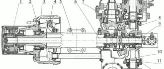
The Soviet SUV UAZ 469, produced by the Ulyanovsk Automobile Plant, is unique in its own way. The diagram of the rear axle of the machine is shown in Fig. 1. The design includes the following key components and assemblies:
- 1 — protective overlap;
- 2 — roller bearing of the differential device;
- 3, 8 — corrective auto-linings;
- 4 — tail part of the drive gear support;
- 5 — adjustment ring;
- 6 - oil removal holder;
- 7 - nut;
- 9 — front gear of the rear axle;
- 10 — head bearing support;
- 11 — hydraulic washer of the gear wheel axle shaft;
- 12 - gear element.
Front and rear axle structure of UAZ 469
FRONT DRIVING AXLE OF THE UAZ-469
CAR The front axle of the car is driven. The crankcase, main gear and differential of the front axle do not differ from the corresponding parts and assemblies of the rear axle, with the exception of the oil slinger ring of the drive gear, which has a right-hand thread and the mark “P” (only in UAZ-469B vehicles).
All disassembly, assembly, maintenance, adjustment and possible malfunction operations are the same as for the rear axle.
The design of the steering knuckle of the front drive axle of the UAZ-469 car is shown in Fig. 71, and the UAZ-469B car in Fig. 72.
To the casing 26 (Fig. 71) and 2 (Fig. 72) of the axle shaft, a ball joint 2 and 5 with pin bushings 9 and 19 pressed into it is attached with five bolts. The steering knuckle housing 5 and 6 is mounted on the ball joint using two kingpins 6 and 9, to which the wheel gear housing cover is bolted. The trunnion 18 and 12 and the brake shield are attached to the cover with six bolts.
The steering knuckle pins are installed with a preload, the value of which is 0.02.. 0.10 mm. From turning in the steering knuckle body, the pins are locked with pins 22 and 11. Adjust the preload using spacers 4 and 20, installed at the top - between the steering knuckle lever (on the right) 29 and 1 or the pad (on the left) 7 and 5 and the steering knuckle body, at the bottom - between the linings and the steering knuckle housing of the front axle of the UAZ-469.
Rice. 71. Steering knuckle of the front axle UAZ-469: a - signal groove; I — right steering knuckle; II — left steering knuckle; III - wheel release clutch; 1 - oil seal; 2 — ball joint; 3 — steering knuckle hinge; 4 - gasket; 5 — grease nipple; 6 — kingpin; 7 — overlay; 8 — steering knuckle housing of the front axle of the UAZ-469 ; 9 — pin bushing; 10 - ball bearing; 11 — driven shaft of the wheel reducer; 12 — hub; 13 — leading flange; 14— movable coupling; 15 — retainer ball; 16 — protective cap; 17 — coupling bolt; 18 — axle; 19 — lock nut; 20 and 23 — support washers; 21 - drive gear; 22 — locking pin; 24 — rubber sealing ring; 25 — thrust washer; 26 — axle shaft casing; 27 — rotation limitation bolt; 28 — wheel rotation limiter; 29 — steering knuckle lever.
To retain the lubricant in the steering knuckle body and protect it from contamination, an oil seal is installed on the ball joint, consisting of an inner race, a rubber ring 24 and 24 with a spring, a partition ring, a felt sealing ring and an outer race. The oil seal is bolted to the steering knuckle housing. To prevent lubricant from flowing from the main gear housing to the steering knuckle, there is a self-clamping rubber seal 1 and 3 in a metal cage inside the ball joint. To lubricate the upper kingpins and add grease to the ball joint, grease fittings 5 and 10 are installed on the steering knuckle lever (right) and on the upper kingpin pad (left). The lower kingpins are lubricated with grease flowing by gravity from the ball joint.
Rice. 72. Steering knuckle of the UAZ-469B car: a - signal groove; I — right steering knuckle; II — left steering knuckle; III - wheel release clutch; 1 — steering knuckle lever; 2 — axle shaft casing; 3 - oil seal; 4 - gasket; 5 — ball joint; 6 — steering knuckle body; 7— support washer; 8 — overlay; 9 — kingpin; 10 — grease nipple; 11 — locking pin; 12 - axle; 13 — wheel hub; 14 — leading flange; 15 - movable coupling; 16— coupling bolt; 17 — retainer ball; 18 — protective cap; 19 — pin bushing; 20 - gasket; 21 — inner race; 32 — ring-partition; 23 — outer ring; 34 — rubber sealing ring; 25 — felt sealing ring; 26 — thrust washers; 27 — rotation limitation bolt; 28 — wheel rotation limiter.
A constant angular velocity joint is installed inside the steering knuckle. The design of the hinge ensures the constancy of the angular velocities of the drive and driven shafts regardless1 of the angle between them. hinge of the UAZ-469 consists of two forks, in the curved grooves of which four balls are located. In the central sockets of the forks there is a fifth ball, which is an adjustment ball and serves to center the forks. From longitudinal movement, the hinge is limited by thrust washer 25 and 26 and ball bearing 10 (Fig. 71). Internal: the drive fork of the hinge is connected by splines to the side gear of the differential, and at the end of the outer driven fork, on splines only for the steering knuckle of the UAZ-469 vehicle, a drive gear 21 of the wheel reducer and a roller bearing are installed, which are locked with nut 19. Driven: gear of the internal wheel reducer is connected by bolts to shaft 11, rotating in a roller bearing installed in the wheel gear housing cover, and to a bronze bushing installed inside axle 18. At the end of shaft 11 there is a device for disconnecting the front wheels of the car, which consists of a movable coupling 14 and 15 (Fig. 71, 72), installed on the splines of the shaft and bolt 17 and 16 with a spring and a ball. The movable coupling is connected by external splines to the internal splines of the drive flange 13 and 14, bolted to the knee hub. To reduce wear on the parts of the front axle of the UAZ-469 and save fuel when operating the vehicle on paved roads, along with turning off the front drive axle, it is advisable to turn off the front wheel hubs. To do this, remove the protective cap 16 and 18 and, unscrewing the bolt 17 and 16 from the hole in the shaft 11 (Fig. 71), install the coupling in a position where the signal ring groove “a” on its surface is located in the same plane with the end of the flange. Having installed the coupling in the required position, screw on the protective cap. Turn on the wheel by tightening bolts 17 and 16 (Fig. 71, 72) and tightening it securely. Perform turning on and off operations simultaneously on both wheels of the front drive axle. Engaging the front axle with the wheels off is not allowed. The design of the wheel gear of the front axle of the UAZ-469 car is similar to the design of the wheel gear of the rear axle and differs from it in the installation and fastening of the drive gear and the design of the ball bearing 10 (Fig. 71), which is installed in a special cup. The drive gear is installed on the involute splines of the driven fork of the hinge and secured together with the bearings with a special nut 19, which, after tightening, is drilled into the groove of the shaft of the UAZ-469 front axle. A support washer 20 is installed between the gear and the roller bearing. The drive gear and ball bearing of the front gearboxes are not interchangeable with similar parts of the rear gearboxes. Otherwise, the front gearboxes are designed identically to the rear gearboxes and require the same maintenance.
Adjustment
Before you start adjusting, prepare everything you need: bushings for the axle (if there is a groove on the axle), 4 thrust bushings, as well as oil seals. The main condition for adjustment is that the two halves of the CV joint do not dangle, both during straight-line movement and when turning! The procedure is as follows:
During the assembly process after repair, it is necessary to lubricate all the bolts with nigrol so that next time everything can be easily unscrewed. All mating surfaces (the junction of the axle and the steering knuckle housing) must be cleaned of dirt. It is not recommended to lubricate the CV joint with grease, as it is thick. When heated under the influence of centrifugal force, all the solid oil will be scattered over the walls of the ball joint, and it is necessary that the CV joint balls be generously lubricated. To do this, it is recommended to dilute the solid oil by half with nigrol.
After final assembly and repair, one more important adjustment needs to be made. We are talking about an adjusting rotary bolt. This is the bolt that limits the maximum angle of rotation of the wheel. It is important not to overdo it; do not tighten the bolt all the way - otherwise the wheel will jam. Tighten almost to the end, and then try to turn the wheel (more precisely, the shaft on which it will stand). It is necessary to unscrew the bolt back until the wheel stops wedging. The rotation angle should be no lower than the factory one. Well, now you yourself can repair the front axle on the 469 UAZ!
PS
: on the rear - there is nothing special to break there, since there are no rotating parts (knuckle, CV joint). Just periodic maintenance, lubricating the parts - and it will last a long time. The most that can break is the gearbox. In general, UAZs, and specifically 469 UAZs, were produced with so-called “military” bridges, which were distinguished by greater reliability and maneuverability. Therefore, many owners of tuned UAZs install them for themselves.
On UAZ vehicles of the old model range, two types of drive axles were installed. Front and rear axles with final drives were installed on hooded vehicles of the UAZ-459B and UAZ-31512 families, and wagon-mounted vehicles of the UAZ-3741, UAZ-3303, UAZ-3962 and UA3-2206 families. U-shaped front and rear axles with wheel gearboxes were installed only on vehicles of the UAZ-469 and UAZ-3151 families.
Installation of U-shaped drive axles with wheel reduction gears, complete front and rear axles, on vehicles of the UAZ-469B and UA3-31512 families is possible with the simultaneous installation of shafts of UAZ-469 and UAZ-3151 vehicles. Installing U-shaped axles with wheel reduction gears on a family of wagon-type vehicles is very difficult, as it will require significant modifications to the design of the bridges, bipod, bipod linkage, vehicle suspension, and the manufacture of cardan shafts for these vehicles that are shortened by 10 mm.
Rear axle with wheel reducers of UAZ-469, UAZ-3151 cars, general arrangement.
The rear axle housing is split in a vertical plane and consists of two parts: a housing and a cover, connected by bolts. The main gear consists of one pair of bevel gears with a spiral tooth: drive and driven. The final drive ratio is 2.77. The main gear drive gear is mounted on two tapered roller bearings. Between the inner rings of the bearings there is a spacer sleeve, an adjusting ring and shims.
An adjusting ring is installed between the inner ring of the bearing and the end of the drive gear. The flange is connected to the drive gear using splines. The drive gear bearings are tightened using a nut, which is then cottered. To prevent oil leakage from the crankcase, the design includes an oil seal.
The driven gear of the main gear is installed on the gearbox and bolted to its flange. The bevel differential, with four satellites, has a split box consisting of two halves connected by bolts. The differential is mounted on two tapered roller bearings. Washers are installed between the axle gears and the ends of the satellite box
Between the ends of the satellite box and the inner rings of the bearings there are adjusting shims. On the left axle housing there is a safety valve connecting the internal cavity of the bridge with the atmosphere.
Wheel reducers of the rear axle of UAZ-469 and UAZ-3151.
Designed to increase ground clearance, which accordingly increases the vehicle's cross-country ability. The wheel reducer consists of one pair of spur gears with internal gears with a gear ratio of 1.94. The gearbox housing is detachable in a vertical plane and consists of two parts: a housing and a cover, connected by bolts.
The drive gear is mounted on the splined end of the axle shaft between a ball (inner) bearing and a roller (outer) bearing. The inner ring of this bearing is locked with a ring, and the outer ring is installed in a removable housing, which is attached to the wheel gear housing support with two bolts. The ball bearing is locked in the crankcase by a ring. An oil deflector is located between the bearing and the crankcase.
The driven gear of the wheel reducer is centered on the shaft collar and bolted to its flange. The driven shaft rests on a bushing and a roller bearing, which is locked with a nut. Unlike the left wheel gearbox, the driven gear shaft and the nut of the right gearbox have a left-hand thread. On the nut, the left-hand thread is marked with an annular groove, and on the shaft with a blind drilling with a diameter of 3 mm at the end of the splined end.
Maintenance of the rear axle with wheel reduction gears of UAZ-469 and UAZ-3151 vehicles.
It consists of maintaining the required oil level in the crankcases and changing it in a timely manner, checking seals, timely detection and elimination of axial play in the final drive gears, periodically cleaning the safety valve and tightening all fasteners. The oil level in the crankcases should be at the lower edges of the filler holes. The oil is drained through the drain holes located in the lower part of the crankcases, and the filler plugs are also turned out.
Axial play of the main gear drive gear is not allowed, since if it is present, rapid wear of the gear teeth occurs and the rear axle may possibly jam. If it appears, the bearings must be adjusted. Axial play is checked by rocking the drive gear by the shaft mounting flange.
Axial play of the driven gear of the main gear is also not allowed. The check is carried out through the oil filler hole. To eliminate the axial play of the driven gear of the main gear, which appeared during operation, it is necessary to add a package of gaskets of the required, but always the same thickness, on the left and right sides of the satellite box, ensuring that the driven gear rotates with little effort. If you add spacers of different thicknesses to the left and right sides of the gearbox, the engagement of worn-in gears will be disrupted, which will lead to rapid breakage of their teeth.
After a run of 50,000 kilometers, during the next maintenance, the bolts securing the driven gear of the wheel reduction gear and the driven gear of the main drive are tightened with a torque of 6.5-8 kgf, as well as the bolts of the removable bearing housing are tightened with a torque of 6.5-8.0 kgf.
Adjustment of the gaps in the mesh of gears and in the bearings of the rear axle is carried out only when replacing gears or bearings, or when axial play appears in the drive or driven gears of the main gear. Replacement of main gears is carried out only as a set.
Rear axle UAZ-469
Components and parts of the rear axle of the UAZ-469, spare parts: 1 — main gear housing cover; 2 — differential bearing; 3 — adjusting gasket; 4 - sealing gasket; 5 and 7 — drive gear bearings; 6 — adjusting ring; 8 — oil seal; 9 - flange; 10 - nut; 11 — mud deflector; 12 - oil removal ring; 13 — adjusting shims; 14 — spacer sleeve; 15—adjusting ring; 16 — drive gear of the main gear; 17 — satellite; 18 — right axle shaft; 19 — wheel gear housing; 20 and 29 — oil deflector; 21 — axle bearing; 22 — retaining ring; 23 — sealing gasket of the gearbox housing; 24 — wheel gear housing cover; 25 — bearing; 26 — retaining ring; 27 — brake shield; 28 — brake drum; 30 — wheel mounting stud; 31 - axle; 32 — hub bearing; 33 - gasket; 34 — lock washer; 35 — leading flange; 36 — hub bearing nuts; 37 — lock washer; 38 — bushing; 39 — driven shaft of the wheel reducer; 40 — retaining rings; 41 — gaskets; 42 — oil seal; 43 — driven shaft bearing; 44 — driven gear of the wheel reducer of the rear axle of the UAZ-469; 45 - special nut; 46 and 50 - drain plugs; 47 — drive gear of the wheel reducer; 48 — right satellite box; 49 — shims; 51 — main gear housing; 52 — axle gear washer; 53 — axle gear; 54 — satellite axis; 55 — driven gear of the main gear; 56 — left satellite box; 57 - left axle shaft.
How to measure the mounting height of the drive gear bearing of the UAZ-469 main gear
How to roll the bearing rollers of the UAZ-469 differential
Gaps A and A1 between the ends of the bearings and the gear box of the UAZ-469
Typical contact spots on the teeth of the driven gear of the final drive during forward and reverse gears. UAZ-469: I - forward side; II - reverse side
Features of unit dismantling
Bulkhead of the VAZ rear axle gearbox
When removing the rear axle, you need to unscrew the tail unit nut, remove the washer, counterflange, cover of the front roller gear assembly, and press the assembled gear with bearings out of the oil cooler at the rear of the car.
This circuit is excellent for disassembling a differential device. The next step is to unscrew the splines connecting the driven gear to the gearbox and reset it. Divide both parts of the box, pull out the gears, planetary gear rods, support nuts
When assessing disassembly, pay attention to the integrity of the gear wheel teeth. If they are damaged, the part must be replaced
To remove rollers, outer and inner rings, special tools are required. Strictly study and understand the disassembly sequence so that you can accurately perform all steps in reverse order when reassembling.
When inspecting the oil stripper ring, check for surface irregularities. If yes, process to a thickness of 5 mm. The same goes for the cardan flange. Grinding height up to 53 mm. Wash the protective surfaces. Blow out the oil outlets. Drive design parts and axle shafts should be replaced if there are scuff marks or severe wear.
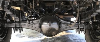
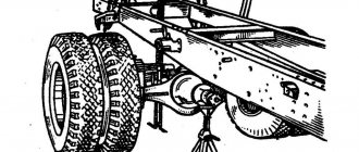
Rear axle structure of UAZ 469
The rear axle of the car is structurally different from the front axle. It does not have a wheel turning mechanism. The rear axle is driven by a cardan shaft from the transfer case. The rear axle consists of the following elements:
Carter
The crankcase consists of two halves. They are connected to each other using bolts. At the bottom of the crankcase there is a hole for draining lubricant. From the side of the wheel mechanisms, axle housings are pressed into the crankcase. In the front part there is a hole for installing the drive shaft.
REFERENCE: The UAZ-469 model is equipped with two types of bridges - military and collective farm. Depending on the type of bridge, the crankcase design differs.
Gearbox
The rear axle of the UAZ 469 has a gearbox consisting of a main gear and a cross-axle differential. The main drive gear is small in size. It transmits torque to the driven gear. The gear teeth are angled. This design allows to reduce the noise level during operation of the unit.
On one side, a drive gear is installed on the drive shaft. On the other side there is a flange necessary for attaching the propeller shaft. To prevent slippage of the drive shaft, splines are provided in the flange. The flange is secured with a nut.
Device and characteristics
The design of the UAZ front axle in older models has few differences from the similar design in new models (Spicer). The main differences lie in the design of the crankcase, the dimensions of the components of the drive gear and differential, and in a number of units used.
The design of the old model is in many ways similar to the rear axle of the UAZ and consists of the following components:
- The key place is occupied by the split crankcase, consisting of 2 separate parts.
- Each half is equipped with press-in housings with internal axle shafts.
- Safety valves on the casings, responsible for controlling the growth of oil volume in the mechanism.
- The differential and main gear of the casing are made according to the standard design: a small-diameter drive gear is located in the horizontal plane, in contact with the cardan.
- The large driven gear in the longitudinal plane is in mesh with the main gear. It has a built-in differential of 4 satellites.
- The edges of the crankcase housing are equipped with pivot joints made of ball joints with a rotating housing.
A design feature of the Spicer bridge is the presence of a contact system between the wheel hub and the axle shaft. It is a coupling responsible for connecting and disconnecting 2 elements. The mechanism ensures the transmission of torque to the wheel from the differential. The disconnected clutch leads to free rotation of the wheel on the axle, and the vehicle receives a 4*2 wheel arrangement. The engaged clutch leads to the connection of the hub, differential and axle shaft, the car turns into a 4*4 all-wheel drive.
Old UAZ car models were distinguished by the presence of hubs with drum brake units.
Their wheel rotation angle is no more than 29°. The knuckle and linkage arms connected to each other are a wheelbase control tool. In new models (Spicer), the angle of rotation reaches 32°. The rest of the bridge structure is similar.
What is the difference between a UAZ military bridge and a civilian one?
The military axle, unlike the civilian Spicer front axle, is equipped with final drives. This design feature caused the following differences between military models:
- Gear axles are located 4 cm above the wheels. This difference helps to increase vehicle clearance - the distance between the supporting surface and the bottom of the bridge.
- The main pair is smaller in size and has a small number of large teeth, which increases the reliability of the design. The unit weighs more.
- The gear ratio is 5.38 (traction, but not speed).
- The length of the rear propeller shaft is 1 cm shorter.
Advantages of military bridge models:
- increased ground clearance by 8 cm;
- high torque, allowing you to transport heavy objects, tow and move at low speeds over difficult terrain;
- load evenly distributed between the main and final drives;
- larger teeth increase reliability;
- limited slip differential for off-road driving.
The military design of the UAZ was thought out to accompany tank colonies, which indicates the power and reliability of the design.
Front axle UAZ 469
The design of the front axle is different from that of the rear axle. The crankcase is shifted to the right edge in the direction of travel of the car. This is due to the location of the transfer case. The front axle is driven by a driveshaft from the drive shaft. The axle is equipped with rotating mechanisms and steering rods that are used to control the vehicle.
The driver can turn on the front axle on the UAZ 469 without leaving the cabin. To do this, transfer case control levers are installed between the driver and passenger seats. One lever is responsible for turning the front axle on and off. The second is necessary to reduce torque transmission.
Half shafts
The axle shafts have different lengths. This is due to the location of the gearbox. To transmit torque to the wheel mechanisms, regardless of the angle of rotation, CV joints are provided.
IMPORTANT: The design of the front axle of the UAZ 469 provides for disconnecting the axle shafts from the wheel hubs. The connection is made with a specialized screw. This design allows you to increase the service life of the gearbox when driving on good quality surfaces and saves fuel.
Carter
The front axle housing is made of two parts connected by bolts. To avoid pressure build-up when the lubricant heats up, the crankcase is equipped with a breather valve. It allows the air mass to freely escape into the atmosphere. The breathing valve is protected from dust and contamination by a cap.
Steering
The wheel mechanisms are connected to each other by a transverse rod. The rod connection is hinged. To adjust the wheel toe angle, the rod is equipped with ends with threaded connections.
The forces from the steering column are transmitted to the bipod of one of the steering knuckles. The steering knuckles are equipped with king pins.
Blog about UAZ
Adjustment of the gaps in the meshing of gears and in the bearings of the drive axle of UAZ-3741, UAZ-3962, UAZ-3909, UAZ-2206, UAZ-3303 cars is carried out only when replacing gears or bearings, or when axial clearance appears in the driving or driven gears of the main transfers. Replacement of main gears should only be done as a complete set.
Adjustment of the bearing of the drive gear of the main drive of the drive axle must be done by selecting the thickness of the shim pack and tightening the flange nut. The bearing must have such a preload that there is no axial movement of the drive gear and the gear can be rotated by hand without much effort.
Check the bearing preload with a dynamometer. At the same time, disconnect the left half of the crankcase. Remove the drive gear bearing cap so that cuff friction does not affect the dynamometer readings. With proper adjustment, at the moment of turning the drive gear by the hole in the flange, the dynamometer should show a force of 1.5-3 kgf for run-in bearings and 2.0-3.5 kgf for new bearings.
If axial play of the drive gear appears during vehicle operation, tighten the flange nut. If the axial play is not eliminated, then reduce the thickness of the shim pack and adjust the bearing as indicated above.
After adjustment, monitor the heating of the bearings while driving. A slight heating of the bearing is not dangerous, but if the neck of the drive axle crankcase heats up to a temperature of 90 degrees or higher, the water on the crankcase boils, this means that the bearing has been overtightened and the overall thickness of the gaskets should be increased.
Adjustment of the differential bearings must be done by selecting the thickness of the package of adjusting shims installed between the ends of the inner rings of both bearings and the gearbox. When replacing main gears and differential bearings, make adjustments in the following sequence:
1. Press the inner rings of the differential bearings onto the journals of the assembled differential so that there is a gap of 3-3.5 mm between the ends of the gearbox and the ends of the inner rings of the bearings.
2. Remove the axle shafts and install the differential assembly with the driven gear into the crankcase, install the gasket and cover, tighten the cover mounting bolts and, turning the driven gear with a mounting blade through the neck of the crankcase, roll the bearings so that the rollers take the correct position. Then use fasteners to evenly and completely connect the cover to the crankcase.
3. Unscrew the fasteners again
Carefully remove the cover, remove the differential from the axle housing and use a feeler gauge to measure the gaps A and A1 between the ends of the gearbox and the ends of the inner rings of the bearings.
4. Select a package of gaskets with a thickness equal to the sum of gaps A+A1. To ensure preload in the bearings, add a 0.1 mm thick spacer to this package. The total thickness of the gasket package should be A+A1+0.1 mm.
5. Remove the inner rings of the differential bearings. Divide the selected pack of gaskets in half. Install the gaskets on the journals of the satellite gearbox and press the inner rings of the bearings until they stop. After this, adjust the side clearance by moving the driven gear.
When replacing only the differential bearings, measure and compare the height of the new and old bearing assemblies. If the new bearing is higher or lower than the old one by some amount, then reduce the thickness of the existing gasket package in the first case and increase in the second case by the same amount.
Node maintenance
The axles of the UAZ 469 are distinguished by their reliability and durability. For normal operation of units, they must be regularly maintained. To do this you need:
- Inspect the crankcase and wheel mechanisms for lubricant leaks;
- Check the degree of tightening of the fastening bolts;
- Replaces lubricant;
- Clean the breathing valve from dirt and check its functionality;
- Check the integrity of gaskets and seals;
- Check the play of the front axle turning mechanism.
Nuances of installation and adjustment
The assembly (diagram) of the differential drive structure is carried out as follows.
- Connection of both satellite boxes depending on the case serial number.
- A crosspiece is inserted into the left satellite box.
- Place the assembled gear in the left box.
- Lubricate the differential units (axle gears, satellites, axles, thrust washers) with transmission oil.
- Secure the necks of the gear rings of the axle shafts with support washers.
- The satellites must be secured to the axis of the disconnected cross.
- Carry out the same actions with the right box.
- Tighten the parts of the boxes, insert the driven wheel of the base gear.
The foreman goes through the unit
Turn the six axle shafts of the mounted differential using splines with a force of no more than 59 N. Adjustment of the drive structural elements is carried out when replacing them.
- Secure the inner rings of the differential bearing units to the journals; the end play between the box and the rings should approach 3.5-4.0 mm.
- The installed differential differential is closed with an auto-gasket and a reservoir cap. Roll the bearings to establish the correct position. Secure the heat exchanger lock.
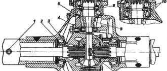
Installation and adjustment of ball bearings of the conductive gear of the rear converter.
- Fixing the guide elements to the main gear.
- Grinding in the tail end with the guide element.
- Location of the spacer and spacers for the roller assembly between the inner rings.
- The main fastener for the main gear adjusting ring.
All intermediate actions, punching, are shown in the diagram in Fig. 2. This diagram describes all the nuances in more detail.
- When adjusting the head gear assembly, there should be no longitudinal play; the spring dynamometer will show the force. Indicators for new parts are 15-30 N, for run-in parts - 20-35 N. To reduce the tension when installing bearings, you can add spacers. To increase - remove.
- The adjustment has come to an end, we fix all the parts in their places and secure them with high-quality cotter pins.
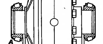
The backlash adjustment and the location of the central gear gear are carried out as follows.
- A potential with adjusted prefabricated roller bearings is installed in the heat exchanger, their separation gasket is installed with a cover secured with a bolt.
- The distance between both teeth is set: 0.2-0.6 mm. The backlash is adjusted taking into account the number of driven gear oil seals: when their number decreases, the backlash must increase, and vice versa. When rearranging the gaskets, the tension of the potential elements will not be disrupted only when the number of gaskets does not change.
- The meshing diagram of gear wheels along the contact patch is shown in Fig. 3.
Possible malfunctions and ways to eliminate them
You can repair the front or rear axle of a UAZ 469 yourself. This will require a standard set of tools and minimal technical knowledge. Possible malfunctions:
Presence of oil smudges
The appearance of oil streaks on the crankcase body or at the hub mounting points indicates a violation of the sealing of the unit. The cause of the violation may be failure of the breathing valve. When heated, the lubricant expands and pressure is created in the axle cavity. Under the influence of pressure, the integrity of gaskets and seals is compromised.
To eliminate the malfunction, it is necessary to restore the functionality of the breathing valve and replace the failed seals.
IMPORTANT: When installing gaskets, it is necessary to treat their surfaces with sealant. Lubricant should be added after the sealant has completely dried.
Increased noise
An increased noise level during operation indicates severe wear of the rotating parts or water entering the unit. When driving off-road or fording, water enters the axle cavity through the breathing valve. This leads to poor lubrication of rotating parts.
To prevent water from entering, car owners are upgrading the design of the breathing valve.
To do this, remove the standard cap. Connect the outlet of the breathing valve to a rubber hose. The second end of the hose is secured in the engine compartment.
A crunching sound when the unit operates indicates a malfunction of the bearings. To eliminate the malfunction, it is necessary to replace the failed parts.
Gear failure
When the main drive gears or cross-axle differential fail, an increased noise level or incorrect operation of the unit is observed. For repairs, you need to replace worn components with new ones.
ATTENTION: The main gears are replaced in pairs, regardless of the degree of wear of each of them. Replacing one gear will lead to its rapid failure.
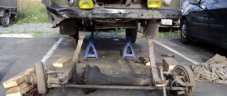
Removing the bridge from the car
In order to repair and adjust the unit, it is necessary to remove the UAZ 469 axle from the vehicle. Dismantling is carried out in the following sequence:
- Place the car on a viewing hole or overpass;
- Immobilize the vehicle with anti-recoil devices;
- Remove the shock absorbers;
- Unscrew the propeller shaft mounting bolts;
- Remove the steering arm rod;
- Remove the brake system pipeline;
- Unscrew the nuts securing the springs;
- Jack up the car body;
WARNING: To avoid personal injury, the vehicle must be supported by stands after lifting.
- Remove the front or rear axle.
The performance of the gearbox is checked at a specialized stand. This allows you to check the correct operation of the node, both under load and without it. Installing the axle on the vehicle is carried out in the reverse order.
From the above it follows that the front and rear axles of the UAZ 469 model are distinguished by their reliability and simplicity of design. The design of the front axle is distinguished by the presence of a wheel turning mechanism necessary for steering the vehicle. Repairs are carried out independently by car owners without the use of specialized equipment.
Increasing the service life of the structure
There are several ways to increase the service life of the UAZ structure. The presence of a front axle in a vehicle imposes special requirements for operation. If you monitor and disable the hubs of the axle shafts and wheels at the right time, this will help increase the service life of the mechanism parts when the front-wheel drive is turned off. To prevent mechanical damage to drive components, turn on after the couplings. After switching from off-road to highway, you should immediately switch to rear-wheel drive. Another reason that contributes to rapid wear of rubber is constantly working clutches.
Machine maintenance must meet a number of requirements:
- Periodicity.
- Regular check of main components and mechanisms.
- Timely replacement of worn parts.
- Monitoring the level of oil and other liquids.
- Checking and adjusting wheel bearings.
- Monitoring the functionality of the main gear axial clearance components.
- Use of high-quality consumables and mixtures.
UAZ bridges
Many axle options were installed at the factory on UAZ vehicles of different models and at different times. Let's try to figure this out...
UAZ Timken bridge (civilian or collective farm)
This is a split type bridge, that is, a bridge consisting of two halves. A military bridge (also known as a gear or portal bridge) can also be classified as this type. From the factory, civilian axles are installed on UAZ trucks of the cargo range (loaf, flatbed, farmer), as well as on passenger cars of the UAZ-3151 (469) range.
Timken front civil axle for UAZ 469 and loaf vehicles Timken rear axle (civilian) for UAZ 469 and loaf vehicles Photo of the gearbox of a half civil bridge Photo of the shank of the Timken civil bridge
The UAZ Hunter is equipped with so-called hybrid axles, with a stocking from conventional Timken axles and a steering knuckle from Spicer.
Gear ratios of the Timken bridge (civilian).
Until July 1989, civil axles were equipped with a main pair with a gear ratio of 5.125 (41 teeth), now - with a gear ratio of 4.625 (37 teeth), i.e., more “fast” but less “powerful”. You can find both in stores. You will most likely have to replace the “new” with the “old” main pair when installing very large wheels. It is recommended to replace the main pairs only as a complete set (in the front and rear axles), otherwise the front axle will have to be turned on only in mud, snow, sand, etc., so as not to damage the transfer case or spoil the tires. How to determine the gear ratio? You need to twist the cardan by hand and count the revolutions of the wheel. For example, 46 cardan revolutions - 10 wheels = 4.6 pair, etc.
Main pair for UAZ, Timken axles, hybrid, 37-8, 4.625
Weight of UAZ civil bridges:
- front axle - 132 kg
- rear axle - 100 kg
Geared (military) axles UAZ
Essentially this is the Timken Bridge, i.e. split, but it has a smaller central gearbox and has final drives. The factory installed military bridges on UAZ 469 vehicles for the army and UAZ, Bars. UAZ Bars bridges are military bridges, but with a wider gauge.
UAZ military axles Photo of UAZ military axles Photo of the UAZ final drive Photo of the UAZ rear military axle UAZ Bars portal axles UAZ Bars axles installed on the UAZ Bukhanka
Gear ratios of UAZ military bridges
The gear ratio of military axles is 5.38 (=2.77*1.94 - the gear ratios of the main and final drives, respectively) - more high-torque, but less high-speed than conventional axles.
Characteristics of a military bridge
- Ground clearance: 300 mm (with tires Ya-192 215/90 R15 (31 x 8.5 R15)
- Track: 1445 mm
- Gear axle track of UAZ Bars: 1600 mm
- Weight of the UAZ front military axle: 140 kg
- Weight of the UAZ rear military axle: 122 kg
Diagram of a UAZ gear (military) axle
UAZ rear axle with final drive:
1 – main gear housing cover; 2 – differential bearing; 3,13,49 – adjusting shims; 4 – sealing gasket; 5.7 – drive gear bearings; 6.15 – adjusting rings; 8.42 – cuffs; 9 – flange; 10 – nut; 11 – mud deflector; 12 – ring; 14 – spacer sleeve; 16 – main gear drive gear; 17 – satellite; 18 – right axle shaft; 19 – final drive housing; 20.29 – oil deflectors; 21 – axle bearing; 22,26,40 – retaining rings; 23 – sealing gasket of the final drive housing; 24 – final drive housing cover; 25 – bearing; 27 – brake shield; 28 – brake drum; 30 – wheel mounting bolt; 31 – axle; 32 – hub bearing; 33.41 – gaskets; 34 – lock washer; 35 – leading flange; 36 – hub bearing nut; 37 – lock washer; 38 – bushing; 39 – final drive driven shaft; 43 – driven shaft bearing; 44 – final drive driven gear; 45 – special nut; 46.50 – drain plugs; 47 – final drive drive gear; 48 – right cup of the satellite box; 51 – main gear housing; 52 – axle gear washer; 53 – axle gear; 54 – satellite axis; 55 – driven gear of the main gear; 56 – left cup of the satellite box; 57 – left axle shaft
Scheme of the UAZ rear military axle
Steering knuckle of the UAZ front axle with final drive:
a – signal groove;
I – right steering knuckle; II – left steering knuckle; III – wheel release clutch (for an alternative design, see Fig. 180, IV); 1 – oil seal; 2 – ball joint; 3 – steering knuckle hinge; 4 – gasket; 5 – grease nipple; 6 – kingpin; 7 – overlay; 8 – steering knuckle body; 9 – pin bushing; 10 – bearing; 11 – driven shaft of final drive; 12 – hub; 13 – leading flange; 14 – coupling; 15 – locking ball; 16 – protective cap; 17 – coupling bolt; 18 – axle; 19 – lock nut; 20.23 – support washers; 21 – final drive drive gear; 22 – locking pin; 24 – rubber sealing ring; 25 – thrust washer; 26 – axle housing; 27 – rotation limitation bolt; 28 – wheel rotation limiter; 29 – steering knuckle lever Diagram of the steering knuckle of the front military axle with final drive
UAZ 452 Loaf Logbook Preparing the car. Part 6 Rear axle.
There are definitely problems with the rear axle. It remains to find out how bad everything is; to do this, you need to remove and wash the rear axle.
I put it on the wheel, halved it and took out the differential.
The outer races of the differential bearing cannot be pulled out so easily.
After everything was removed, I disassembled and washed the differential and hubs.
The bearings were completely damaged; pieces even broke off from the rear bearing of the drive gear.
The main couple also had a good time.
The thrust washers of the axle gears are heavily worn and have worn out grooves in the housing.
The outer ring of the bearing in the right hub rotated and broke the seat. Brake drums and pads are in good condition. The brake cylinders, like the front ones, are new, you just need to replace the boots.
As a result, it is necessary to change all the differential bearings, the main pair, half-axle gear washers and the right hub assembly. The UAZ spare parts store already knows me, they even gave me a discount card.
After purchasing the necessary spare parts, I began assembly. By selecting the thickness of the washer, I eliminated the gap between the semi-axial gears and satellites.
The seats for the front and rear bearings of the drive gear were slightly broken, so I had to resort to tinning again. After which the bearings were pressed into place with good tension.
Then there was magic with the differential setting, which released a lot of hatred and obscenities. It seems like nothing complicated, but when you start doing it yourself and for the first time, it becomes “fun.” But everything worked out, and the bridge was assembled.
All you have to do is push it back and you're done.
During disassembly I purchased front springs in good condition, which I will replace in the next part.
Military bridges on UAZ Bukhanka
Military (geared) UAZ loaf axles are chosen by car enthusiasts because of their reliability. Such a bridge, as its name suggests, has gearboxes that distribute part of the load applied to the main pair.
The advantages of military bridges are as follows:
- greater ground clearance - standard axles have a length of 22 centimeters, the nominal value of the gearbox is 30 (in practice, this value is not achieved if the cars use the same tires). The maximum increase is possible when using Y-192 tires on the UAZ;
- higher torque value, which allows you to transport larger loads, tow and move at low speeds on muddy roads;
- the main pair is more reliable - its teeth are larger;
- the resulting load is evenly distributed;
- The presence of a limited slip differential means that the car does not slip when off-road.
Buy military bridges
- in a specialty store. The cost of such a purchase will be much higher than if purchased secondhand, but the purchased part has been assembled by the manufacturer and will be new.
- from the hands of the owner of a similar model of UAZ loaves. Purchasing a used part will cost less than a new spare part. There is also a negative point in this - good quality and normal working condition are not always guaranteed. Before buying a used part, you should carefully inspect it - perhaps there are shortcomings that are not noticeable during a cursory examination, due to which the bridge will soon become unusable.
Installation of gear (military) axles on a UAZ loaf
But when installing new axles, it is impossible to do without intervention in the steering system - driving becomes dramatically more difficult, which can lead to a serious accident.
Therefore, the main stage in installing a military bridge will be to correct the steering system to meet the new requirements - it is necessary to unload the steering bipod. This issue is solved by installing block sports with hydraulic cylinders - such actions are the most optimal.
Strengthening the bipod by any available means without changing the steering system will sooner or later lead to the destruction of the mounts and the disconnection of the bridge.
During the installation process you will need:
- dismantle the civil bridge from the loaf;
- adjust the position of the swing arm;
- begin installing the gear axle, while simultaneously making corrections to the vehicle's steering mechanism.
Fuel consumption on a loaf with military axles
After changing the axles on a car, fuel consumption per hundred kilometers, according to those who have already made the change, increases. The difference between the previous consumption is from 1.5 to 2 liters.
This becomes especially noticeable in the winter season.