Design
It is worth noting that the MAZ 5440 gearbox consists of:
- from the main pair (drive and driven gears);
- stalletite axes;
- satellites;
- differential housings;
- bearings;
- adjusting washer;
- crankcase
Each of the listed mechanisms has a certain operational resource. Sometimes they wear out sooner. The need to repair or replace the gearbox or components is indicated by fractures, chips on the surface, and extraneous noise, as mentioned above.
The exact cause of the malfunction can only be determined after the gearbox has been removed and inspected. Without this, we can only guess what caused the breakdown.
Dismantling and defect detection of the central gearbox of the MAZ middle axle
During repairs, the central gearbox of the middle axle is disassembled in the following sequence:
- remove the differential lock mechanism 20 (Fig. 41);
- unscrew the bolts and remove the crankcase 7 as an assembly with the axle drive shaft 30 and the center differential 29;
- when removing, the crankcase must be rotated by the flange to ensure that the differential comes out from behind the gear;
- remove flange 77;
- unscrew the cover fastening bolts 15;
- Using a universal puller, remove the cup together with bearing 14 from shaft 30 and differential lock clutch 19;
- unscrew the bolts securing the center differential cups 29 and remove the cup with gear and bearing from shaft 30;
- remove the locking ring, pin and unscrew the nut securing the crosspiece 28;
- remove the cross 28 from the shaft 30;
- remove gear 25 assembled with bearings 13 using a puller;
- remove the inner ring of the outer bearing of the spur gear using a puller with mandrel 3 (Fig. 255);
- during partial disassembly, when it is necessary to remove only the axle drive shaft 30 (Fig. 41) assembled with the center differential 29, unscrew the cover bolts 15 and remove the axle drive shaft together with the center differential. In this case, to remove it, it is necessary to turn the shaft 30 to set the flat on the differential cups so that the cups do not touch the gear 10. To remove, if necessary, the inner ring of the cylindrical bearing of the center differential, use a universal puller;
- unscrew the nuts and remove the drive gear 3 with the bearing housing 8 and spur gear 10 assembled;
- clamp the drive bevel gear 3 in a vice (the jaws of which are covered with soft metal pads);
- unscrew nut 11 and remove gear 10;
- remove the inner ring of the inner tapered bearing from the shaft of drive gear 3 using a puller with mandrel b (Fig. 247);
- if necessary, press out the outer rings of bearings 9 from the crankcase 8 (Fig. 41) using a puller (Fig. 248);
- remove stoppers 50 (Fig. 41) and differential bearing covers 48;
- remove differential 43 assembly;
- unscrew the nuts of the bolts securing the differential cups and disassemble the differential 43 using dismantling bolts;
- remove satellites 1, semi-axial gears 45, washers 46;
- If necessary, remove differential bearings 47 using a puller;
- unscrew bolts 36 (Fig. 41) and remove shaft 32 assembled with bearings 35;
- unscrew nut 40 and disassemble the shaft;
- if necessary, disassemble the differential lock mechanism 20.
The disassembled gearbox parts must be washed and the condition of the working surfaces of the bearings and gears checked. Gear teeth should not have chips, cracks, chipping of the cementation layer, or severe wear. If there is a slight stepwise wear of the teeth, the steps are cleaned; It is also necessary to clean the nicks and burrs on the gear teeth.
The wear of the teeth of bevel gears along the thickness is characterized by the amount of lateral clearance. The gap is measured with an indicator from the side of the larger diameter.
If there is increased noise from the gears of the central gearbox, a side clearance of 0.8 mm can serve as a basis for replacing the bevel gear pair. If necessary, the drive and driven bevel gears are replaced as a set, since at the factory they are selected in pairs based on the contact patch and side clearance. When replacing bevel gears, a pair of middle axle gears must be installed. Installation of rear axle gears is not allowed.
When inspecting differential parts, you should pay attention to the condition of the surface of the spider journals, holes and spherical surfaces of the satellites, supporting surfaces of the semi-axial gears, bronze support washers and the end surfaces of the differential cups. These surfaces should not have scuffing or significant wear.
When defecting parts of the rear and middle axles of a car, you should be guided by the nominal and permissible dimensions given in table. 58.
If the pinion bushing is significantly worn or loose, it must be replaced. Processing of the new bushing must be done after pressing it into the satellite to a diameter of 32+0.05 mm.
If there is significant wear on the bronze support washers of the semi-axial gears and satellites, the washers must be replaced. The thickness of the new bronze washers is 1.5 mm.
Before assembly, the seating and mating surfaces of the gearbox parts must be lubricated with operating oil, it is recommended to lubricate the sealing gaskets with grease, sealing paste or nitro paint, and the working edges of the oil seals with Litol-24 lubricant.
The bearings must be washed in kerosene and then lubricated with operating oil.
Disassembly and defect detection of MAZ gearbox
Common faults
Bearing wear is one of the most common causes. This happens due to insufficient oil level in the gearbox housing, poor-quality bearing or its significant wear. The damage can be eliminated by replacing the bearing.
If the bearing falls apart while the vehicle is moving, its rollers can break the insides of the gearbox. The situation is dangerous because the gearbox itself can jam. In this case, the scope of repairs increases significantly. It must be performed at specialized service stations.
The weak point of the gearbox is the satellite gears. They crumble if the car is regularly operated under a load significantly exceeding the permitted load. The gears also need replacing.
To avoid the problems described above, gears and bearings must be changed regularly, within the time limits established by the manufacturer in the regulations. You shouldn’t skimp on the quality of components either, since repairs due to their premature failure will cost many times more.
Drive axles of Maz-5516, 5340, Maz-6430, 64229, Maz-5440, 54323, 54329 cars
_______________________________________________________________________________________
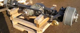
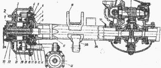
The rear axle of Maz-5516, 5340, Maz-6430, 64229, Maz-5440, 54323, 54329 cars has a double spaced main gear, consisting of a central bevel gearbox and planetary wheel gears located in the wheel hubs (Figures 11, 12). The middle drive axle of cars Maz-5516, 5340, Maz-6430, 64229, Maz-5440, 54323, 54329 - Consists of a central gearbox (Figure 13) and planetary wheel gears. The cross-axle differential and wheel gears of the middle axle are maximally unified with similar units of the rear axle. The drive of the locking mechanism for the center and cross-axle differentials of the middle axle is electro-pneumatic. The locking of the cross-axle differentials of the middle and rear axles of the Maz-5516, 5340, Maz-6430, 64229, Maz-5440, 54323, 54329 vehicles is carried out by one switch, regardless of whether the center differential lock is turned on. The locked position of the differentials is indicated by warning lamps. The locking of the cross-axle and cross-axle differentials should be turned on when negotiating difficult and slippery sections of the road with the car stopped or when driving at low speed (up to 10 km/h) and turn off the lock on sharp turns of these sections of roads. Engaging the lock in wheel slip mode is not allowed. Maintenance and adjustment of Maz-5516, 5340, Maz-6430, 64229, Maz-5440, 54323, 54329 axles Maintenance of Maz-5516, 5340, Maz-6430, 64229, Maz-5440, 54323, 54329 drive axles consists of maintaining the required level of lubrication in the central gearboxes and in wheel drives, changing it in a timely manner, cleaning the breathers from contamination, checking and tightening fasteners, checking the operating noise and heating temperature of the axles, as well as making adjustments to the meshing of bevel gears and the tension in tapered bearings. If a lubricant leak is detected through the cuffs of the input and output shafts of the middle axle and the drive gear of the rear axle, the cause of the leak should be determined. Replace the cuffs of the input and output shafts of the middle axle and the drive gear of the rear axle Maz-5516, 5340, Maz-6430, 64229, Maz-5440, 54323, 54329 in the following sequence: - disconnect the propeller shaft from flange 14 (Fig. 11); — undo the cotter pin and unscrew the nut 15 securing the flange, remove the sealing ring 16 and flange 14; — unscrew the fastening bolts 13 and remove the cover with cuffs; — replace the cuffs by filling their internal cavities with Litol-24 lubricant and reassemble the unit in the reverse order of disassembly. Cuffs 14, 42 (Fig. 13) and 17, 18 (Fig. 11) are pressed into the covers until they stop. Tighten the flange mounting nuts, checking the minimum torque value and then tightening until the shaft hole coincides with the nut slot. In this case, the turning torque of the drive bevel gear should be in the range of 0.1 - 0.3 kg/cm. Adjust the tension of the bearings of the drive bevel gears, axle differentials and the output shaft of the middle axle Maz-5516, 5340, Maz-6430, 64229, Maz-5440, 54323, 54329 after 60-80 thousand kilometers while simultaneously tightening the nut 15 of the flange 16 ( Fig.3). After 180 thousand km, at the next maintenance - 2, the axle housings should be washed. Removing the central bevel gear of the axle for adjustment work should be done in the following sequence: - drain the oil from the axle crankcase and wheel drives (by unscrewing the drain and filler plugs); — disconnect the driveshaft; — disconnect the air supply hose from the gearbox locking cylinder, disconnect the pressure sensor terminals, unscrew the sensor; — remove covers 23 (Figure 12) of wheel gears; — block the cross-axle differential (using a bolt); — remove the axle shafts 13 together with the drive gears 27 of the wheel drives; — Unscrew the nuts of the studs securing the gearbox to the axle housing (except for the top two). After this, roll the trolley with the lift under the gearbox and, ensuring reliable support of the gearbox on the lift, unscrew the remaining two upper nuts. Then, using two dismantling bolts in the flange mounting the gearbox to the axle housing, remove the gearbox. Assembly is carried out in reverse order. When disassembling the wheel drive of the Maz-5516, 5340, Maz-6430, 64229, Maz-5440, 54323, 54329 bridge: - drain the oil from the wheel drive, installing the wheel so that the drain plug is in the lowest position, unscrewing the drain and filler plugs 21 , 24 (Figure 12); — unscrew nuts 2 and remove cover 23; — remove the axle shaft 13 together with the drive gear 27; — unscrew the bolts and remove the brake drum 10; — remove the carrier body together with satellites 28 and carrier 22; — use a special wrench to unscrew locknut 19, remove the lock washer, unscrew nut 17 and remove driven gear 20 together with hub 18; — remove hub 5 together with bearings. Reassemble the wheel drive in reverse order. The satellite axles must be installed with their flats facing the center of rotation of the wheel drive. When removing the wheel hub, the wheel drive must be disassembled in the same sequence. When removing axle shafts 13 (Figure 12) and 36, 54 (Figure 26) without dismantling the central gearbox, it is imperative to lock the cross-axle differentials of the rear and middle axles and unlock them only after installing the above axle shafts. Adjust the gearbox of the drive axle Maz-5516, 5340, Maz-6430, 64229, Maz-5440, 54323, 54329 with the gearbox removed in the following sequence: - adjust the tension of the bevel bearings of the drive bevel gear; — adjust the tension of the differential bearings; — adjust the engagement of the bevel gears according to the contact patch and lateral clearance, and then (if necessary) adjust the tension of the differential bearings.
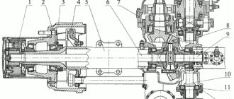
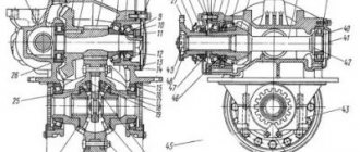
Fig. 11. Rear axle gearbox Maz-5516, 5340, Maz-6430, 64229, Maz-5440, 54323, 54329 1 - locking mechanism cylinder, 2 - piston; 3 - screw; 4 - nut; 7 — fork for engaging the locking mechanism; 8 — gear housing; 9 — driven gear; 10,12,26,32 — bearing, 11 — bearing cup; 13 - bolt; 14 - flange; 15 - nut; 16 — sealing ring; 17, 18 — cuff; 19 — gasket; 20 - adjusting gaskets; 21 — oil deflector; 22 — drive gear; 23 — satellite; 24, 31 — differential cup; 25, 33 — nut; 27, 29 — axle gear; 28 — cross; 30 — support washer; 34 — differential lock clutch; 35 — axle housing. In this case, in order to avoid violating the initial adjustment of the bearings, nuts 25, 33 (Figure 11) should be unscrewed and screwed to the same angle. To adjust the bearings of the drive bevel gear Maz-5516, 5340, Maz-6430, 64229, Maz-5440, 54323, 54329: - remove the drive bevel gear with the bearing housing assembly. To do this, unscrew the nuts securing the 11 bearing cup in the rear axle gearbox housing and remove the cup with the gear using dismantling bolts. In the middle axle gearbox of Maz-5516, 5340, Maz-6430, 64229, Maz-5440, 54323, 54329, unscrew the bolts securing the gear housing and, using the dismantling bolts, remove the gear housing assembled with the input shaft, bend back the locking plates, unscrew the nuts securing the housing intermediate and remove it assembled with the drive bevel gear; — determine the axial clearance in the bearings with an indicator; — secure the drive gear in a vice (protecting it from damage with soft metal spacers); — remove flange 14 (Fig. 11), cover with cuffs 17, 18 or gear 9 (Fig. 13), inner ring of the bearing closest to the shank and adjusting gasket 20; — measure the thickness of the adjusting shim and calculate its required thickness to eliminate axial play and obtain preload of the bearings (the reduction in the thickness of the shim should be equal to the sum of the axial play measured by the indicator and the bearing preload value equal to 0.03-0.05 mm); — grind the adjusting shim to the required size and assemble the drive gear without securing the cover with cuffs.
Fig. 12. Wheel drive of the drive axle Maz-5516, 5340, Maz-6430, 64229, Maz-5440, 54323, 54329 1 - satellite axis; 2 - nut; 3 — needle bearing; 4.7 - bearing: 5 - hub; 6.8 - bolts; 9 - ABS sensor; 10 — brake drum; 11 — shield; 12 - axis; 13 - axle shaft; 14 — expansion fist; 1 5 — brake pad; 17, 19-nut; 18-hub driven gear; 20 — driven gear; 2! — drain plug; 22 - carrier; 23 - cover; 24 - filler plug; 25 - cracker; 26 — axle stop; 27 — drive gear; 28 -satellite.
Fig. 13. Middle axle gearbox Maz-5516, 5340, Maz-6430, 64229, Maz-5440, 54323, 54329 1.12 - satellites; 2.50 — support washers; 3.17 — adjusting gasket; 4.23 - drive gear; 5.7, 13, 18, 29, 31, 39, 51 - bearing; 6 — spacer sleeve; 8, 24, 25, 30, 38 — adjusting washers; 9 — driven gear; 10 — gear housing; 11, 15, 34, 44, 52 - nut; 14, 42 — cuff; 16, 43 — flange; 19, 45 — cover; 20 — center differential locking clutch; 21 - ring; 22 — retaining ring; 26, 48 — differential crosspieces; 27 — center differential; 28 — axle drive shaft; 32 — cylinder of the locking mechanism; 33 - screw; 35 — rear axle drive shaft; 36, 54 — axle shafts; 37 — cross-axle differential locking clutch; 40 — cup of bearings; 41 - bolt; 46 — driven gear; 47 — cross-axle differential; 49 — axle gear; 53 — nut stopper; 58 - ring.
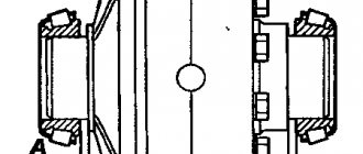
Adjusting the engagement of the bevel gears of the central gearbox of the driving axles Maz-5516, 5340, Maz-6430, 64229, Maz-5440, 54323, 54329 When tightening the flange nut, the bearing cup should be rotated to correctly place the rollers in their cages; — check the bearing tension by the rotation torque of the bearing cup, which should be equal to 1 - 3 Nm (0.1 - 0.3 kg/cm). With normal preload in the bearings, remove flange 14 (Fig. 11), replace the cover with cuffs 17, 18 and finally assemble the unit. Adjust the tension of the differential bearings with the drive gear removed using nuts 25 (Figure 11) and 52 (Figure 13). Screw the nuts to the same depth until the required preload is obtained, without disturbing the position of the driven gear. The bearing preload is determined by the amount of torque required to rotate the differential, which should be within 2-5 Nm (0.2 -0.5 kg/cm) with the drive gear removed. This moment is determined by a special torque wrench or by measuring the force applied at the radius of the differential cups and equal to 23 - 57 N (240 - 586 kgf). The procedure for checking and adjusting the engagement of the bevel gears of the Maz-5516, 5340, Maz-6430, 64229, Maz-5440, 54323, 54329 axle gearbox is as follows: - before installing the bearing cup with the drive gear in the gearbox housing, wipe the teeth of both bevel gears and on the side surfaces apply a thin layer of paint with three to four teeth; — using the table, adjust the engagement of the bevel gears. The movement of the drive gear is ensured by changing the number of shims under the flange of the drive gear bearing housing. To move the driven gear, you should use nuts 25 (Fig. 11) or 52 (Fig. 13), so as not to disturb the tension adjustment in the differential bearings, screw (unscrew) the indicated nuts to the same angle. Adjust the differential bearings of the drive axle Maz-5516, 5340, Maz-6430, 64229, Maz-5440, 54323, 54329 (Figure 13) in the following sequence: - disconnect the driveshaft from flange 16; — remove the differential lock mechanism; — Unscrew the bolts securing the gear housing and remove the housing assembly with the center differential; — disassemble the center differential, remove the drive gear and remove the bearings from the gear; — wash the parts in diesel fuel and lubricate them before assembly; — install the internal bearing into gear 23 until it stops; — install the outer ring 21, the inner ring 58 and the outer race of the outer bearing; - to ensure preload in the bearings, reduce the thickness of the set of washers 24 by the amount of the axial clearance plus 0.02 - 0.03 mm and install them in place; — install retaining ring 22; — install the inner race of the bearing assembled with the separator. To check the preload in the bearings, install gear 23 with bearings on the press table, through a mandrel (supported on the end of the inner race of the inner bearing) and compress the bearings with a slight force. By rocking, check for the presence of axial play and the ease of turning the gear. As a mandrel, you can use the crosspiece 26 and the spacer sleeve assembled with the gear. The turning force of the drive cylindrical gear applied on its outer diameter should be in the range of 5.5 - 22 N (0.55 - 2.2 kgf). Adjustment of the bearings 39 of the output shaft of the Maz-5516, 5340, Maz-6430, 64229, Maz-5440, 54323, 54329 bridges can also be done by changing the set of adjusting washers 38 in the following sequence: - unscrew the bolts 41 and remove the output shaft 35 with the bearing housing 40; — wash the parts in diesel fuel and lubricate them before assembly; — clamp the shaft in a vice, install the inner race of the inner bearing with the separator on the shaft; — install cup 40 assembled with the outer bearing races; — install the required set of adjusting washers 38, the thickness of which should be reduced by the amount of the axial clearance plus 0.02 - 0.03 mm; — install the separator and the inner race of the outer bearing; — install flange 43, tighten the nut. By rocking and turning flange 43, check for axial clearance. The turning force applied at the radius of the holes in the flange must be in the range of 6.4 - 25.5 N (0.65 - 2.6 kgf). After adjustment, unscrew the nut and remove the flange 43, install the cover 45 with cuffs 42 and, having assembled the unit, tighten the flange nut. In this case, the holes for the cotter pin must coincide with the slot in the nut. Then tighten the nut and reinstall the shaft with bearing assembly and flange assembly. The thickness S of the gasket package 17 (Figure 13) for adjusting the preload of tapered bearings 18, 31 when compressed with a force of P = 800 N is determined by the formula: S = (H - P ± 0.1) ± 0.05 mm. Adjustment of the lateral clearance in the meshing of the center differential gears is carried out using a set of washers 25, 30. With a compression force of 800N, it should be in the range of 0.1 - 0.55 mm. Before assembling the gearboxes of the rear and middle axles MAZ-5516, 5340, MAZ-6430, 64229, MAZ-5440, 54323, 54329 on one of the mating surfaces, as well as between the gaskets in connectors B (Fig. 11) and in connectors B, D , E (Figure 13), a layer of sealant should be applied. Adjusting the locking mechanisms of the cross-axle and center differentials of the Maz-5516, 5340, Maz-6430, 64229, Maz-5440, 54323, 54329 axles Adjusting the locking mechanism of the cross-axle differential of the rear axle Maz-5516, 5340, Maz-6430, 64229, Maz-5440, 54323, 54329 is carried out on the assembled central gearbox, before installing it in the axle housing, in the following order (Fig. 11): - measure the gap A between the end of the coupling 34 and the differential cup, the value of which should be A = 1 + 0.3 mm. In this case, the coupling 34 must be held coaxially with the cup 31 using a mandrel; — unscrew the bolts securing the locking mechanism cylinder 1 and remove it together with the piston; — having unscrewed nut 4 of the fork rod screw, tighten or unscrew screw 3 by the amount of required movement of the fork to ensure clearance A = 1+0.Zmm, tighten nut 4 to a torque of 44 - 56 N mm and install the cylinder. Adjust dimension A=1+0.5mm (Figure 13) of the center differential locking mechanism using shims 56. Adjust dimension B=1+0.5mm using screw 33. After adjustment, tighten nut 34 with a torque from 44 to 56 Nm (4.4 - 5.6 kg/cm). Adjusting the bearings of the rear wheel hubs of Maz-5516, 5340, Maz-6430, 64229, Maz-5440, 54323, 54329 Raise the axle and free the wheels from the load. Check that the wheel rotates freely under hand pressure and that there is no axial play in the hub. If the wheel rotates tightly or axial play of the hub is detected, adjust the bearings, while simultaneously checking the serviceability of the cuffs for the absence of oil leaks. Adjust the hub bearings of the drive axles Maz-5516, 5340, Maz-6430, 64229, Maz-5440, 54323, 54329 in the following order: - drain the oil from the wheel drive; — disassemble the wheel drive as described above; - turning the hub, tighten nut 17 (Fig. 12) to a torque of 400 - 500 Nm (40 - 50 kg/cm), then unscrew it 60 - 75 degrees and check the hub for ease of rotation. It should rotate freely by hand, axial play is not allowed; — install the washers, tighten locknut 19 to a torque from 392 to 490 Nm (40 - 50 kg/cm) and lock it with the bend of the lock washer; — check again the rotation of the hub and the absence of axial play. The correctness of the adjustment can be determined by the mileage of the car based on the degree of heating of the hub, the temperature of which should not exceed 60°C (at higher temperatures the hand cannot withstand prolonged touch).
_______________________________________________________________________________________
_______________________________________________________________________________________
- 970 Elite
- TLB 860
- Cat 422
- Cat 428
- Cat 434
- Cat 444
- 3 CX Super
- 4 CX
- 5 CX
- WZ30-25
- XT860/XT870
_______________________________________________________________________________________
- WB 97S
- WB 93R
- Hyundai H940S
- B110
- B115
- Hidromek HMK 102B
- Hidromek HMK 62SS
_______________________________________________________________________________________
- Mobile cranes
- Cranes manipulators
- Motor graders DZ-122,143
- Excavator EK-14
- Kamaz truck repair
- MAZ truck repair
- TL 65
- TL 120
- TL 310
- Cat 914
- Cat 924
- Caterpillar 950
- Caterpillar 966
_______________________________________________________________________________________
- LW500F
- ZL30G
- ZL50G
- LW321F
- XGMA XG932
- XGMA XG955
- Design of Terex, Komatsu, Cat loaders
- ZW250
- ZW310
- ZW220
- ZW180
- W130
- W170
- W190
- W270
- L34
- Adjusting the D-180 engine
- Transmission T-170
- Assembly of gearboxes T-170, T-130
- Adjusting the T-170 clutch
- Hydraulic and mounted systems T-170
- Main gear T-170, T-130
- Diesel injection pump D-160
- Servo mechanism of clutch T-130, T-170
- Onboard clutches T-130
- Final drive of the T-130 tractor
- Rotation control mechanism T-130
- Hydromechanical transmission TO-18/TO-18B
- Hydraulic system GMP TO-18/TO-18B Amkodor
- Hydraulic system TO-18
- Hydraulic system components TO-18/TO-18B Amkodor
_______________________________________________________________________________________
- Design of rack and pinion hydraulic cylinders
- Types of positive displacement hydraulic pumps
- Rotary screw pumps - Design and operating principle
- Characteristics and design of gear pumps
- Pump control diagram in a closed hydraulic system
- Hydraulic distributor device with proportional control
- Hydraulic systems of special equipment - operation and maintenance
- Application of hydrostatic transmissions for special equipment
- Application of cartridge electrically controlled valves
- Design and diagrams of cartridge plug-in hydraulic valves
- Characteristics of Screw-in Hydraulic Cartridge Valves
- Sequence valve and pressure reducing valve operating diagrams
- Variable displacement hydraulic pump regulator
- Load Sending System for Variable Pumps
- Hydraulic distributors - Control systems
- Control diagrams for working hydraulic units of special equipment
Diagnostics
The gearbox is disassembled in stages, after which all components and parts are thoroughly washed. Then it is necessary to inspect the surfaces for chips, cracks, metal fragments, traces of friction, and burrs on gear teeth.
If there are strong signs of wear on the driven or driving gears, the entire main pair must be replaced. If the parts are in good condition, then they do not need to be replaced.
- Diagnostics and repair of differential and final drive
TRUCKS GAZ, ZIL, KAMAZ, URAL, MAZ, KRAZ
_________________________________________________________________________________________
Maintenance of drive axles of MAZ-5516, 5440 vehicles
The rear axle of Maz-5516, 5340, Maz-6430, 64229, Maz-5440, 54323, 54329 cars has a double spaced main gear, consisting of a central bevel gearbox and planetary wheel gears located in the wheel hubs (Figures 11, 12). The middle drive axle of cars Maz-5516, 5340, Maz-6430, 64229, Maz-5440, 54323, 54329 - Consists of a central gearbox (Figure 13) and planetary wheel gears. The cross-axle differential and wheel gears of the middle axle are maximally unified with similar units of the rear axle. The drive of the locking mechanism for the center and cross-axle differentials of the middle axle is electro-pneumatic. The locking of the cross-axle differentials of the middle and rear axles of the Maz-5516, 5340, Maz-6430, 64229, Maz-5440, 54323, 54329 vehicles is carried out by one switch, regardless of whether the center differential lock is turned on. The locked position of the differentials is indicated by warning lamps. The locking of the cross-axle and cross-axle differentials should be turned on when negotiating difficult and slippery sections of the road with the car stopped or when driving at low speed (up to 10 km/h) and turn off the lock on sharp turns of these sections of roads.
Engaging the lock in wheel slip mode is not allowed. Maintenance and adjustment of Maz-5516, 5340, Maz-6430, 64229, Maz-5440, 54323, 54329 axles Maintenance of Maz-5516, 5340, Maz-6430, 64229, Maz-5440, 54323, 54329 drive axles consists of maintaining the required level of lubrication in the central gearboxes and in wheel drives, changing it in a timely manner, cleaning the breathers from contamination, checking and tightening fasteners, checking the operating noise and heating temperature of the axles, as well as making adjustments to the meshing of bevel gears and the tension in tapered bearings. If a lubricant leak is detected through the cuffs of the input and output shafts of the middle axle and the drive gear of the rear axle, the cause of the leak should be determined. Replace the cuffs of the input and output shafts of the middle axle and the drive gear of the rear axle Maz-5516, 5340, Maz-6430, 64229, Maz-5440, 54323, 54329 in the following sequence: - disconnect the propeller shaft from flange 14 (Fig. 11); — undo the cotter pin and unscrew the nut 15 securing the flange, remove the sealing ring 16 and flange 14; — unscrew the fastening bolts 13 and remove the cover with cuffs; — replace the cuffs by filling their internal cavities with Litol-24 lubricant and reassemble the unit in the reverse order of disassembly. Cuffs 14, 42 (Fig. 13) and 17, 18 (Fig. 11) are pressed into the covers until they stop. Tighten the flange mounting nuts, checking the minimum torque value and then tightening until the shaft hole coincides with the nut slot. In this case, the turning torque of the drive bevel gear should be in the range of 0.1 - 0.3 kg/cm. Adjust the tension of the bearings of the drive bevel gears, axle differentials and the output shaft of the middle axle Maz-5516, 5340, Maz-6430, 64229, Maz-5440, 54323, 54329 after 60-80 thousand kilometers while simultaneously tightening the nut 15 of the flange 16 ( Fig.3). After 180 thousand km, at the next maintenance - 2, the axle housings should be washed. Removing the central bevel gear of the axle for adjustment work should be done in the following sequence: - drain the oil from the axle crankcase and wheel drives (by unscrewing the drain and filler plugs); — disconnect the driveshaft; — disconnect the air supply hose from the gearbox locking cylinder, disconnect the pressure sensor terminals, unscrew the sensor; — remove covers 23 (Figure 12) of wheel gears; — block the cross-axle differential (using a bolt); — remove the axle shafts 13 together with the drive gears 27 of the wheel drives; — Unscrew the nuts of the studs securing the gearbox to the axle housing (except for the top two). After this, roll the trolley with the lift under the gearbox and, ensuring reliable support of the gearbox on the lift, unscrew the remaining two upper nuts.
Then, using two dismantling bolts in the flange mounting the gearbox to the axle housing, remove the gearbox. Assembly is carried out in reverse order. When disassembling the wheel drive of the Maz-5516, 5340, Maz-6430, 64229, Maz-5440, 54323, 54329 bridge: - drain the oil from the wheel drive, installing the wheel so that the drain plug is in the lowest position, unscrewing the drain and filler plugs 21 , 24 (Figure 12); — unscrew nuts 2 and remove cover 23; — remove the axle shaft 13 together with the drive gear 27; — unscrew the bolts and remove the brake drum 10; — remove the carrier body together with satellites 28 and carrier 22; — use a special wrench to unscrew locknut 19, remove the lock washer, unscrew nut 17 and remove driven gear 20 together with hub 18; — remove hub 5 together with bearings. Reassemble the wheel drive in reverse order. The satellite axles must be installed with their flats facing the center of rotation of the wheel drive. When removing the wheel hub, the wheel drive must be disassembled in the same sequence. When removing axle shafts 13 (Figure 12) and 36, 54 (Figure 26) without dismantling the central gearbox, it is imperative to lock the cross-axle differentials of the rear and middle axles and unlock them only after installing the above axle shafts. Adjust the gearbox of the drive axle Maz-5516, 5340, Maz-6430, 64229, Maz-5440, 54323, 54329 with the gearbox removed in the following sequence: - adjust the tension of the bevel bearings of the drive bevel gear; — adjust the tension of the differential bearings; — adjust the engagement of the bevel gears according to the contact patch and lateral clearance, and then (if necessary) adjust the tension of the differential bearings. Fig. 11. Rear axle gearbox Maz-5516, 5340, Maz-6430, 64229, Maz-5440, 54323, 54329 1 - locking mechanism cylinder, 2 - piston; 3 - screw; 4 - nut; 7 — fork for engaging the locking mechanism; 8 — gear housing; 9 — driven gear; 10,12,26,32 — bearing, 11 — bearing cup; 13 - bolt; 14 - flange; 15 - nut; 16 — sealing ring; 17, 18 — cuff; 19 — gasket; 20 - adjusting gaskets; 21 — oil deflector; 22 — drive gear; 23 — satellite; 24, 31 — differential cup; 25, 33 — nut; 27, 29 — axle gear; 28 — cross; 30 — support washer; 34 — differential lock clutch; 35 — axle housing. In this case, in order to avoid violating the initial adjustment of the bearings, nuts 25, 33 (Figure 11) should be unscrewed and screwed to the same angle. To adjust the bearings of the drive bevel gear Maz-5516, 5340, Maz-6430, 64229, Maz-5440, 54323, 54329: - remove the drive bevel gear with the bearing housing assembly. To do this, unscrew the nuts securing the 11 bearing cup in the rear axle gearbox housing and remove the cup with the gear using dismantling bolts. In the middle axle gearbox of Maz-5516, 5340, Maz-6430, 64229, Maz-5440, 54323, 54329, unscrew the bolts securing the gear housing and, using the dismantling bolts, remove the gear housing assembled with the input shaft, bend back the locking plates, unscrew the nuts securing the housing intermediate and remove it assembled with the drive bevel gear; — determine the axial clearance in the bearings with an indicator; — secure the drive gear in a vice (protecting it from damage with soft metal spacers); — remove flange 14 (Fig. 11), cover with cuffs 17, 18 or gear 9 (Fig. 13), inner ring of the bearing closest to the shank and adjusting gasket 20; — measure the thickness of the adjusting shim and calculate its required thickness to eliminate axial play and obtain preload of the bearings (the reduction in the thickness of the shim should be equal to the sum of the axial play measured by the indicator and the bearing preload value equal to 0.03-0.05 mm); — grind the adjusting shim to the required size and assemble the drive gear without securing the cover with cuffs. Fig. 12. Wheel drive of the drive axle Maz-5516, 5340, Maz-6430, 64229, Maz-5440, 54323, 54329 1 - satellite axis; 2 - nut; 3 — needle bearing; 4.7 - bearing: 5 - hub; 6.8 - bolts; 9 - ABS sensor; 10 — brake drum; 11 — shield; 12 - axis; 13 - axle shaft; 14 — expansion fist; 1 5 — brake pad; 17, 19-nut; 18-hub driven gear; 20 — driven gear; 2! — drain plug; 22 - carrier; 23 - cover; 24 - filler plug; 25 - cracker; 26 — axle stop; 27 — drive gear; 28 -satellite. Fig. 13. Middle axle gearbox Maz-5516, 5340, Maz-6430, 64229, Maz-5440, 54323, 54329 1.12 - satellites; 2.50 — support washers; 3.17 — adjusting gasket; 4.23 - drive gear; 5.7, 13, 18, 29, 31, 39, 51 - bearing; 6 — spacer sleeve; 8, 24, 25, 30, 38 — adjusting washers; 9 — driven gear; 10 — gear housing; 11, 15, 34, 44, 52 - nut; 14, 42 — cuff; 16, 43 — flange; 19, 45 — cover; 20 — center differential locking clutch; 21 - ring; 22 — retaining ring; 26, 48 — differential crosspieces; 27 — center differential; 28 — axle drive shaft; 32 — cylinder of the locking mechanism; 33 - screw; 35 — rear axle drive shaft; 36, 54 — axle shafts; 37 — cross-axle differential locking clutch; 40 — cup of bearings; 41 - bolt; 46 — driven gear; 47 — cross-axle differential; 49 — axle gear; 53 — nut stopper; 58 - ring. Adjusting the engagement of the bevel gears of the central gearbox of the driving axles Maz-5516, 5340, Maz-6430, 64229, Maz-5440, 54323, 54329 When tightening the flange nut, the bearing cup should be rotated to correctly place the rollers in their cages; — check the bearing tension by the rotation torque of the bearing cup, which should be equal to 1 - 3 Nm (0.1 - 0.3 kg/cm). With normal preload in the bearings, remove flange 14 (Fig. 11), replace the cover with cuffs 17, 18 and finally assemble the unit. Adjust the tension of the differential bearings with the drive gear removed using nuts 25 (Figure 11) and 52 (Figure 13). Screw the nuts to the same depth until the required preload is obtained, without disturbing the position of the driven gear. The bearing preload is determined by the amount of torque required to rotate the differential, which should be within 2-5 Nm (0.2 -0.5 kg/cm) with the drive gear removed.
This moment is determined by a special torque wrench or by measuring the force applied at the radius of the differential cups and equal to 23 - 57 N (240 - 586 kgf). The procedure for checking and adjusting the engagement of the bevel gears of the Maz-5516, 5340, Maz-6430, 64229, Maz-5440, 54323, 54329 axle gearbox is as follows: - before installing the bearing cup with the drive gear in the gearbox housing, wipe the teeth of both bevel gears and on the side surfaces apply a thin layer of paint with three to four teeth; — using the table, adjust the engagement of the bevel gears. The movement of the drive gear is ensured by changing the number of shims under the flange of the drive gear bearing housing. To move the driven gear, you should use nuts 25 (Fig. 11) or 52 (Fig. 13), so as not to disturb the tension adjustment in the differential bearings, screw (unscrew) the indicated nuts to the same angle. Adjust the differential bearings of the drive axle Maz-5516, 5340, Maz-6430, 64229, Maz-5440, 54323, 54329 (Figure 13) in the following sequence: - disconnect the driveshaft from flange 16; — remove the differential lock mechanism; — Unscrew the bolts securing the gear housing and remove the housing assembly with the center differential; — disassemble the center differential, remove the drive gear and remove the bearings from the gear; — wash the parts in diesel fuel and lubricate them before assembly; — install the internal bearing into gear 23 until it stops; — install the outer ring 21, the inner ring 58 and the outer race of the outer bearing; - to ensure preload in the bearings, reduce the thickness of the set of washers 24 by the amount of the axial clearance plus 0.02 - 0.03 mm and install them in place; — install retaining ring 22; — install the inner race of the bearing assembled with the separator. To check the preload in the bearings, install gear 23 with bearings on the press table, through a mandrel (supported on the end of the inner race of the inner bearing) and compress the bearings with a slight force. By rocking, check for the presence of axial play and the ease of turning the gear. As a mandrel, you can use the crosspiece 26 and the spacer sleeve assembled with the gear. The turning force of the drive cylindrical gear applied on its outer diameter should be in the range of 5.5 - 22 N (0.55 - 2.2 kgf). Adjustment of the bearings 39 of the output shaft of the Maz-5516, 5340, Maz-6430, 64229, Maz-5440, 54323, 54329 bridges can also be done by changing the set of adjusting washers 38 in the following sequence: - unscrew the bolts 41 and remove the output shaft 35 with the bearing housing 40; — wash the parts in diesel fuel and lubricate them before assembly; — clamp the shaft in a vice, install the inner race of the inner bearing with the separator on the shaft; — install cup 40 assembled with the outer bearing races; — install the required set of adjusting washers 38, the thickness of which should be reduced by the amount of the axial clearance plus 0.02 - 0.03 mm; — install the separator and the inner race of the outer bearing; — install flange 43, tighten the nut. By rocking and turning flange 43, check for axial clearance. The turning force applied at the radius of the holes in the flange must be in the range of 6.4 - 25.5 N (0.65 - 2.6 kgf). After adjustment, unscrew the nut and remove the flange 43, install the cover 45 with cuffs 42 and, having assembled the unit, tighten the flange nut. In this case, the holes for the cotter pin must coincide with the slot in the nut. Then tighten the nut and reinstall the shaft with bearing assembly and flange assembly. The thickness S of the gasket package 17 (Figure 13) for adjusting the preload of tapered bearings 18, 31 when compressed with a force of P = 800 N is determined by the formula: S = (H - P ± 0.1) ± 0.05 mm. Adjustment of the lateral clearance in the meshing of the center differential gears is carried out using a set of washers 25, 30. With a compression force of 800N, it should be in the range of 0.1 - 0.55 mm. Before assembling the gearboxes of the rear and middle axles MAZ-5516, 5340, MAZ-6430, 64229, MAZ-5440, 54323, 54329 on one of the mating surfaces, as well as between the gaskets in connectors B (Fig. 11) and in connectors B, D , E (Figure 13), a layer of sealant should be applied. Adjusting the locking mechanisms of the cross-axle and center differentials of the Maz-5516, 5340, Maz-6430, 64229, Maz-5440, 54323, 54329 axles Adjusting the locking mechanism of the cross-axle differential of the rear axle Maz-5516, 5340, Maz-6430, 64229, Maz-5440, 54323, 54329 is carried out on the assembled central gearbox, before installing it in the axle housing, in the following order (Fig. 11): - measure the gap A between the end of the coupling 34 and the differential cup, the value of which should be A = 1 + 0.3 mm. In this case, the coupling 34 must be held coaxially with the cup 31 using a mandrel; — unscrew the bolts securing the locking mechanism cylinder 1 and remove it together with the piston; — having unscrewed nut 4 of the fork rod screw, tighten or unscrew screw 3 by the amount of required movement of the fork to ensure clearance A = 1+0.Zmm, tighten nut 4 to a torque of 44 - 56 N mm and install the cylinder. Adjust dimension A=1+0.5mm (Figure 13) of the center differential locking mechanism using shims 56. Adjust dimension B=1+0.5mm using screw 33. After adjustment, tighten nut 34 with a torque from 44 to 56 Nm (4.4 - 5.6 kg/cm). Adjusting the bearings of the rear wheel hubs of Maz-5516, 5340, Maz-6430, 64229, Maz-5440, 54323, 54329 Raise the axle and free the wheels from the load. Check that the wheel rotates freely under hand pressure and that there is no axial play in the hub. If the wheel rotates tightly or axial play of the hub is detected, adjust the bearings, while simultaneously checking the serviceability of the cuffs for the absence of oil leaks. Adjust the hub bearings of the drive axles Maz-5516, 5340, Maz-6430, 64229, Maz-5440, 54323, 54329 in the following order: - drain the oil from the wheel drive; — disassemble the wheel drive as described above; - turning the hub, tighten nut 17 (Fig. 12) to a torque of 400 - 500 Nm (40 - 50 kg/cm), then unscrew it 60 - 75 degrees and check the hub for ease of rotation. It should rotate freely by hand, axial play is not allowed; — install the washers, tighten locknut 19 to a torque from 392 to 490 Nm (40 - 50 kg/cm) and lock it with the bend of the lock washer; — check again the rotation of the hub and the absence of axial play. The correctness of the adjustment can be determined by the mileage of the car based on the degree of heating of the hub, the temperature of which should not exceed 60°C (at higher temperatures the hand cannot withstand prolonged touch).
_________________________________________________________________________________________
- GAZ-3307 clutch maintenance
- Steering system GAZ-3307
- Gearbox parts for GAZ-3307
- Maintenance of the rear axle GAZ-3307
- Maintenance of the fuel system of the D-245 diesel engine
- Clutch GAZ-3309 with a diesel engine
- Operations for disassembling the GAZ-3309 gearbox
- GAZ-3309 front axle service
- Repair of cardan shafts of GAZ-3309 cars
_________________________________________________________________________________________
_________________________________________________________________________________________
- Operations for assembling basic components of the ZIL-130 engine
- Service and repair operations for the ZIL-130 gearbox
- Maintenance and repair of ZIL-130 clutch
- Repair and adjustment of the rear axle ZIL-130
_________________________________________________________________________________________
- KAMAZ-4310, 43118, 43114
- KAMAZ-5320, 55111, 53212, 5511, 55102
- KAMAZ-65115, 6520, 65117
- KAMAZ-4308
- Engine KAMAZ-740
_________________________________________________________________________________________
- Parts of the cylinder block and head of the YaMZ-236 engine
- Service maintenance of the YaMZ-236 piston group and crankshaft
- Diagnostics and technical adjustments of the YaMZ-236 engine
- Design and adjustment of fuel injection pump and injectors of the YaMZ-236 engine
- Cylinder block and piston YaMZ-238
- Components of the YaMZ-238 diesel fuel supply system
- Design and adjustment of the fuel injection pump of the YaMZ-238 diesel engine
- Technical design of the YaMZ-239 gearbox
_________________________________________________________________________________________
- Components of the front axle and steering rods of the Maz-5516, 5440
- Steering system of Maz-5516, 5440 cars
- Clutch and gearbox parts Maz-5516, 5440
- Maintenance of drive axles of MAZ-5516, 5440 vehicles
- Power steering for Maz-5551, 5335 cars
- Maintenance of cardan transmission of Maz-5551, 5335 cars
- Maintenance and adjustment of clutch MAZ-5551, 5335
- Repair and service of the rear axle of MAZ-5551, 5335 cars
_________________________________________________________________________________________
- Gearbox Ural-4320
- Construction and adjustment of Ural-4320 bridges
- Maintenance of transfer case Ural-4320
- Steering components Ural-4320
_________________________________________________________________________________________
- Servicing the KRAZ-255, 260 gearbox
- Steering mechanism and power steering Kraz-255, 260
- Adjustments and repairs of the power steering cylinder and steering rods of the Kraz car
- Drive axle components and drive shafts Kraz-255, 260