Farmers are interested in how to adjust the MTZ-82 brakes, the design of which they would like to know. Brakes for Minsk Tractor Plant products, including equipment such as the MTZ-82 mini-tractor, are needed so that the tractor driver can reduce the speed of movement, completely stop the agricultural machinery and keep it stationary when required. In addition, the braking system can allow you to maneuver more efficiently and enter braking turns when necessary.
Brake device MTZ-82
The Belarus tractor is usually equipped with dry disc brakes.
They are installed on the shafts of the key gear wheels. They stand on both sides, and special protective covers are placed on top of them. The MTZ-82 brake system consists of several elements:
- Two connecting disks, which are combined with the help of special devices with the final drive gears.
- Friction linings glued to discs.
- A pair of pressure plates, which are made of cast iron material and are connected to the first structural element.
Between the last elements, several expansion balls are installed, which are positioned along the entire circumference with equal distances from each other. These balls must fit into special inclined sockets, which are made from the inside on the pressure disks. Inside, the design of the tractor brakes is completely protected from the leakage of oil contained on the rear axle. The protection is made by installing a special pair of self-clamping cuffs on the lid of the glass. The lid, in turn, receives a seal with a rubber ring.
Service brake
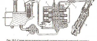
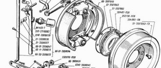
On the MTZ 82 tractor, dry disc brakes are used as the working (main brake) mechanism. They are located at the rear of the axle on the right and left sides, respectively. The figure below shows a diagram of the tractor service brake.
1 — main casing of the brake system; 2 — ball base; 3 — spring base; 4 — disks for connecting parts; 5 — brake system discs; 6 — fork base; 7 — fastening locknut; 8 - bolt for adjustment; 9 — pedal roller; 10 — brake system latch; 11 — washer in the shape of a sphere; 12 — lever of the brake system of the left side; 17 — brake latch on a mountain surface; 18 — braking system rod; 19 — fastening cover.
This brake design is also suitable for models 821 and 80. Typically, these vehicles are equipped with a manual type of brake.
Adjustment of control of both new and old types of brakes is carried out as follows:
- Type A pillows must be installed on the surface and have a thickness of 2-3 mm;
- the nuts of the bolts that perform the adjusting function of the pads should be unscrewed;
- adjust the service brakes;
- return the locknut to its working position.
Parking brake
When the parking brake handbrake is installed correctly, the brakes are completely locked on a slope of up to 18%; this is the main difference between the MTZ82 model and its predecessors.
To adjust this type of brake, the following steps must be carried out:
- the brake is released by moving the lever position forward;
- unscrew the locknut of the adjustment screw 1 and 7 (only after releasing it from the fastening);
- combine indicators with each other: B1 and B2; lever 4 with fork 6;
- insert pin groove 5;
- screw 1 must be tightened until the brake force of 400 N falls on the gap between 3 and 4 clamps.
- tighten the nut until it stops.
Brake system diagram
Before you begin adjusting or repairing this important unit, it is advisable to study the diagram of its structure. With its help, you can find out what the MTZ 82 brake system is, get acquainted with the features of its design and operating principle. This will allow the technician to avoid mistakes when performing maintenance on his own.
Brake device
Tractors in this series are equipped with a dry-type brake system, the main element of which is special discs. They are placed symmetrically on the key shafts, thereby stopping their movement if necessary. To protect such important parts from mechanical damage, durable casings are used, which increases the service life of the disks.
The tractor is in great demand in our country
Studying the MTZ 82 brake design in more detail, it is necessary to highlight several key components that deserve mention. Among them:
- brake discs combined with each other using connecting units;
- friction linings placed on disk mechanisms;
- 2 pressure disks, which are connected to the brake counterparts, are made of high-strength cast iron.
The design of the element provides for the presence of several expanding spherical elements, evenly distributed around the circumference between the disk mechanisms. Special recesses are used to fix them, which ensures correct operation of the unit.
The brake system is reliably protected from the ingress of various substances, for example, lubricants, that can impair their functionality. A glass with cuffs is used as a protective element that does not allow leaks, and its lid is equipped with a rubber seal.
Adjustment
Efficiency is tested on a dry, hard-surfaced road. When braking at a speed of 25 km/h, the braking distance to a complete stop should not exceed 9 meters. The difference in the length of the left and right brake tracks should not exceed 1 meter. If there is a discrepancy, additional adjustments are made to the lagging side.
Adjusting the pedal stroke
The setting consists of adjusting the travel of the drive brake pedals. Proper adjustment ensures even braking on the left and right sides. The pedal stroke should be 70 - 90 mm for tractors with a small cabin; with a large overview cabin, the free stroke should be 110 -120 mm. The adjustment is carried out by changing the length of the adjusting screw 2. An increased pedal stroke reduces braking efficiency, a reduced stroke leads to premature wear of the disc linings. To achieve simultaneous braking with interlocked pedals, the travel of the left brake pedal must be 5-20 mm less than the travel of the right one.
Adjusting the brake pedal free play
Adjusting the parking brake
Correctly setting the handbrake ensures complete blocking of the wheels and holds the tractor on a slope of 18%. Adjustments are made in the following order:
- set the lever to the forward position, releasing the brake
- unscrew the locknut of the adjusting screw 1 and the locknut 7, then release the connecting pin,
- turn lever 4 and align the upper edge of groove B1 of lever 2 with the upper edge of groove B2 of lever 3 of the right brake pedal, and then, rotating fork 6, align the holes of lever 4 and fork 6 and insert pin 5
- By tightening or unscrewing screw 1, select the position in which the brake is tightened with a lever with a force of 400 N in the position between the third and fourth click of the latch. Finally, tighten the control nuts of the adjustable rods.
Adjusting the MTZ 80 brake drive
Adjusting the trailer pneumatic brake control drive
The mechanical control drive is connected in parallel to the control drive of the pneumatic brake valve. To ensure timely supply of air pressure to the working chambers of the trailer brakes during braking, the length of the “brake valve opening” rod 1 and the force of the “pre-compression” spring 3 installed on the rod are adjusted. The length is adjusted so that in the free position of the brake controls the gap between the upper edges of the grooves and levers 6 and 7 is 1-2 mm. The length of spring 3 should be 37 mm and is adjusted by rotating the thrust nut 2 on the threaded part of the rod 1.
Adjusting the MTZ 80 brake air valve drive
To ensure sufficient force, air regulates the pressure in the pneumatic line for controlling the trailer brakes. To adjust, disconnect the drive rod 1 in the joint with the pneumatic valve under the rubber casing 8. Unscrew the eye 9 of the joint several turns and by rotating the adjusting nut set the pressure in the line to 7.7 kgf/cm2. Then fix the position with a lock nut, connect the eye with the rod and install the rubber casing.
Disassembly and repair of tractor brakes MTZ-80, MTZ-82
If during the process of braking the tractor was pulled to the side and at the same time you noticed an increased travel of the brake pedals, know that your tractor either has worn out brake disc linings or a “jamb” in the adjustment of the brake control mechanism. In such cases, they usually start checking the full travel of the brake pedals.
It should be within 70-90 mm for your breadwinner and be identical (read the same). Otherwise, everything is adjusted according to Fig. 2.8.3. First, slightly loosen the lock nut, and then, screwing the adjusting bolt into the fork or turning it out, make the pedal stroke correct
In such cases, they usually begin to check the full travel of the brake pedals. It should be within 70-90 mm for your breadwinner and be identical (read the same). Otherwise, everything is adjusted according to Fig. 2.8.3. First, slightly loosen the lock nut, and then, by screwing the adjusting bolt into the fork or turning it out, make the pedal stroke correct.
What's the next step? Everything here is in accordance with the regulations: the performance of the brakes in motion is assessed. They stupidly accelerate the tractor and brake sharply. Then the work is like that of police investigators, “using tire tread imprints to measure the braking distance.” Then the technicians come in and say: “If everything is fine, the length does not exceed 7 m.” While checking all these necessary works, you still need to calculate the simultaneous operation of the left and right brakes. Let’s imagine the following situation when braking: the tractor “steers” to the side. With such a disposition, the timing of the brakes is usually adjusted. If everything goes to hell, it is not possible to achieve synchronization by adjustment, the brakes are removed and repaired according to the instructions (Fig. 2.8.4).
To remove the brake on the left side, first remove the differential lock clutch (see Fig. 2.8.5, 2.8.6). The sowing procedure begins with releasing the right cab bracket, the PTO engagement rod and the brake valve (as in Fig. 2.8.7—2.8.9).
Important Guide to tuning the body and interior for the UAZ Bukhanka
After removing the brakes, they begin to measure the thickness of the discs. Disc linings or disc assemblies require replacement when worn to a size of less than 11 mm, and pressure discs require replacement when worn to a size of less than 10.8 mm.
Rice. 2.8.3. Adjusting the brake pedal travel of the MTZ-80, MTZ-82 tractor: 1 - fork; 2 - bolt; 3 - lock nut | Rice. 2.8.4. The relative position of the brake parts and brake control of the MTZ-80, MTZ-82 tractor: 1 - brake disc; 2 - roller; 3 - pedal; 4 — levers; 5 - casing; 6 — pressure plates |
Rice. 2.8.5. How to disconnect the pipeline and remove the cover of the differential locking mechanism of the MTZ-80, MTZ-82 tractor: 1 - pipeline; 2 - cover; 3 - bolt | Rice. 2.8.6. How to remove the differential lock clutch of the MTZ-80, MTZ-82 tractor: 1 - diaphragm cover; 2 - bolt |
Rice. 2.8.7. Disconnecting the cabin bracket and the brake valve of the MTZ-80, MTZ-82 tractor: 1 - bracket; 2 - brake valve; 3 — right rear axle shaft | Rice. 2.8.8. Removing the right brake of the MTZ-80, MTZ-82 tractor: 1 - casing; 2 - bolt |
Rice. 2.8.9. How to remove the brake discs of the MTZ-80, MTZ-82 tractor
Next, dismantling and repair of axle sleeves of tractors MTZ-80, MTZ-82.
Recommendations for routine repairs of MTZ-80, MTZ-82 tractors
Recommendations for use
The reason for poor braking is oil getting on the working discs, causing the friction linings to slip. Lubricant leakage into the brake drum housings occurs as a result of wear of the oil seals that isolate the transmission oil sump and the oil housing of the differential lock clutch connected to the left brake housing of the tractor. Self-clamping rubber seals are installed in the cup lid; the lid itself is sealed with a rubber ring in the groove of the rear axle housing. If oiling of the mechanism is detected, the unit is disassembled and the cause is eliminated. The parts are washed with gasoline and, after drying, assembled.
Loss of brake performance occurs as a result of wear on the disc linings, as well as the appearance of grooves as a result of wear on the working surfaces. If the total wear of the lining thickness exceeds 8 mm, the friction discs are replaced with new ones. It is recommended to change parts on both sides to ensure simultaneous braking of the left and right sides.
Causes of jamming
Many drivers express the opinion that the design of the brakes of the MTZ 82 (80) tractor is unsuccessful and rather capricious in operation. The main complaints about the operation of the system are that the mechanism jams in a braked position. Tractor drivers disagree when discussing the factors that cause jamming, however, the common cause of problems with brake operation and premature wear of parts is contamination of the mechanism. I would like to note that rapid contamination is a consequence of lubricants entering the mechanism, causing dust to stick to the assembly parts.
To determine the causes and eliminate the problem, you need to dismantle the unit and disassemble it. Particular attention should be paid to the condition of the parts of the pressure mechanism and friction discs.
- Contamination of the mechanism can provoke jamming as a result of solid inclusions between the pressure plates. In this case, contamination prevents the discs from returning to their original position after releasing the pedal.
- Deterioration in the inclined grooves of the pressure disks, the appearance of grooves and scuffing, as well as wear of the balls with loss of shape provokes jamming.
- Loss of tension force or loss of pressure plate return springs can also cause a wedge.
- The development of splines on friction disc hubs and shafts creates unacceptable gaps, which are an additional factor in jamming.
- Also, wet brake discs can freeze at subzero temperatures with the parking brake applied.
Principle of operation
Before you figure out how to tighten the brakes on MTZ, you should familiarize yourself with the operating principle of such a unit. It is extremely simple and provides that when you press the pedal, the rods are shifted, activating the roller and lever mechanisms of the brakes. By means of washers and bolts, force is transmitted to the forks, which activate the pressure plates.
Be sure to read: Fuel injection pump on MTZ-82
The system then operates according to the following algorithm:
- The disks unfold, which leads to the movement of spherical elements along the surfaces.
- The linings placed in the disk joints are pressed against the glass of the device, due to which the gears responsible for the movement are braked.
- After a successful stop or cessation of pressure on the brake pedal, all mechanisms return to their original state due to the presence of spring mechanisms located in various places in the structure.
It is allowed to use only one of the brake pedals to stop, which will lead to a partial stop of the moving components and will allow maneuvering when driving the tractor. However, such actions are advisable only at low speeds, which do not exceed 10 km/h, otherwise there will be a high probability of the unit overturning.
Parking brake diagram
A special latch deserves mention, which allows you to successfully fix the position of both brake pedals. With its help, you can provide comfortable conditions when working on a slippery road or slope.
Brake Maintenance
In order to repair the brakes of this tractor model as rarely as possible, you should regularly carry out maintenance of this unit, and also follow the general recommendations for working with it. It is not recommended to clamp the pedals unless absolutely necessary, as this leads to increased wear of the friction linings. You should also adhere to other rules:
- stopping should be carried out smoothly, until the final position of the pedal;
- after use, it is necessary to remove the pedal latch to avoid damage to the mechanisms when starting to move;
- inspection of the main structural parts should be carried out daily.
You should also familiarize yourself in more detail with the procedure for adjusting the brake mechanisms, since it is often required for the correct operation of the unit. If you watch a video on how to adjust the brakes on the MTZ 82, the manipulations will be much easier and more convenient. To adjust, you will need to remove the lock nuts of the bolts, and then screw them into the adjusting forks in such a way as to restore normal pedal travel. After this, it is enough to install the dismantled elements and tighten them for reliable fixation.
Be sure to read: Electrical diagram of GAZ 3309
Brake system of the MTZ-82 tractor, design features and breakdowns
The brake system of the Belarus tractor consists of several types of brakes. A variety of brakes are divided into: standing, spare, backup and main working.
Of course, the main service brake is designed to effectively stop the tractor, as in any vehicle. The disc is used as the main means of braking. The rear axle shaft gears on the right and left are equipped with dry disc brakes.
A parking brake is needed for equipment to keep the tractor in one place, including on slopes and slopes, as well as under the pressure of heavy loads and materials. This may also include heavy attachments.
If you need to hold the car in one position for a long time, then an auxiliary brake is designed for this. It helps even when you are on inclines and inclines.
In turn, the spare brake acts as an insurer in case the main brake system does not work.
Despite the rather simple device, the brake can quickly immobilize the tractor, which can even drive with a load.
At the same time, malfunctions occur with this simple mechanism due to a number of reasons. Problems may include the following:
1. Possible increase in pressure in reverse. In this case, it is either the compressor valves are leaking, or there are problems with the piston rings of the compressor. Pneumatics can also bleed air.
2. When you press the pedal, there is a lightning-fast drop in pressure. In this case, the malfunction may occur either due to a defect in the pneumatic diaphragm, or due to a breakdown of the brake valve inlet valve.
3. The oil supply to the pneumatics may be higher than normal. This occurs when the piston rings in the compressor itself wear out.
4. The pneumatic rod slowly returns to its original position. The return spring or brake pad spring may be damaged. You also need to inspect the rod itself.
5. There is a decrease in the effectiveness of the trailer brake. In this case, there may be several reasons. For example, line pressure may be reduced due to insufficient brake valve supply. Also, it is this brake valve that can cause the pressure to drop to zero. Another problem can occur due to the fact that the brake pipe connector does not allow sufficient pressure to pass through, and as a result it drops to zero.
6. The pressure regulator operates too often, thereby not taking air from the receiver. In this case, most likely the pneumatic system is too depressurized in some place. Therefore, it is imperative to stop the machine and eliminate the depressurization.
Despite the fact that the tractor brake system has backup and auxiliary systems, you should not delay repairing the main system if it has faults. The consequences of indifference to the problem can be unpleasant. The tractor should also be regularly maintained. For example, pneumatics need to be inspected every 960 operating hours. It is necessary to check its tightness, the condition of the fastening and adjust the brake system. The compressor itself is subject to inspection and cleaning every 2000 hours.
How to determine if there are faults in the tractor brake system
The need for repair procedures arises immediately after detecting symptoms of brake system problems such as:
- decrease in brake fluid level (occurs when the pads are worn out, there are leaks due to depressurization of hoses and tubes);
- jamming of adjustments;
- soft or hard pedal, reducing braking efficiency;
- the presence of pulsation or vibration of the pedal, its excessive travel or sinking to the floor;
- whistling, grinding, squealing and other extraneous sounds that occur during braking;
- violation of tractor stability when stopping, etc.
MTZ brakes are usually repaired after disassembling and removing the components. This happens when internal parts fail. The event involves cleaning the system, identifying worn parts and replacing them, subsequent assembly and adjustment.
T 40
The wheeled tractor of the Lipetsk plant, version T 40, is equipped with dry belt-type brakes. They are equipped with two tightening ends with separate controls and a bar for general locking.
Servicing the braking system of the T 40 model involves checking the tightness of the seals, washing the linings and timely adjusting the brake. The first signal of problems in the system and wear of the linings is a change in the free play of the pedal. In this case, it is necessary to adjust the position of the tape:
- unscrew the bolts and remove the hatch cover;
- unscrew locknut 3;
- tighten the nut and check the pedal travel, which should be within 50-80 mm;
- Once the desired parameter is reached, secure the nut with locknut 3.
If the adjustment is carried out correctly, the outer lever of the left brake will move 8° back vertically, and the right one will move 10° back in the same direction. When carrying out work, the pedals must be moved to the rearmost position.
According to the standard maintenance schedule, the brake system is carried out every 240 operating hours. To ensure a uniform gap, change the position of the tape:
- release locknut 16 of screw 15;
- The screw is screwed in until it stops, and then turned another ¾ and secured with a lock nut.
The T 40 tractor requires repairs if the linings become oily. First, they are washed. To do this, remove the hatch cover and pour 1.5-2 liters of kerosene inside. Then the lid is closed and a run-in is carried out, moving the machine back and forth. After stopping the equipment, the spent kerosene is drained by first unscrewing the adjusting screw. After washing, the position of the tape is changed according to the diagram given above. Repeated oiling is eliminated by replacing the sealing ring or cuff.
T 25
The brake system of the T 25 model consists of two floating belts that operate independently of each other. They are installed between the transmission and final drive housings in intermediate sleeves.
The main elements of the system are a steel belt and a cast iron pulley. The tape is supplemented with a friction lining, which provides increased friction between these fragments. Gradually, the lining and the pulley surface wear out, which leads to an increase in the gap between them, a change in the free travel parameters of the pedal and a decrease in braking efficiency.
In the normal state, the gap between the belt lining and the pulley is 1-1.5 mm with a pedal stroke of 30-50 mm. If the measurements differ from the norm, this indicates that the T 25 tractor requires brake adjustment. In this case, as in the MTZ 82 model, they look at the position of the clamping and set screws. Sequencing:
- the locknut and pressure screws are loosened a couple of turns;
- wrap them all the way and check the measurements, the difference between which should not be more than 1 mm;
- loosen the locknut and screws by 2 turns;
- fix screws and bolts;
- screw the hinge until it comes into contact with the conical surface of the lever and tighten the nut.
Adjustment of the brakes of the T25 tractor is carried out every 1000 operating hours or after detecting a violation of the free play of the pedal.
How does the MTZ-82 brake system work?
The brakes on the MTZ-82 operate as follows. When you press the brake pedal, the special brake rods of the cushions move down, thereby turning the roller and levers. After this, the force is transmitted to the forks using spherical washers and bolts. Using traction and fingers, they are firmly attached to the pressure plates. Under the influence of traction, these disks unfold and thereby move the spheres along inclined surfaces, and the disks expand.
Important Front loader Foton FL936F and characteristics of other models
Using the same discs, the linings located on the connecting discs are pressed against the cup cover and the brake casing. After this, the key gear wheels responsible for the final drive slow down, and the tractor wheels stop. The pedals and discs are brought to their original position by the action of special springs and pressure discs.
When braking, all wheels can stop either simultaneously or separately.
In this case, the technique of applying different influences on two pedals is used if it is necessary to provide the tractor with additional maneuverability. Be careful, because you should not allow a single wheel of agricultural machinery to brake when the machine accelerates at more than a speed of 10 km/h. This is dangerous because it can ultimately cause the machine to tip over. In order to simultaneously use the right and left brakes, it is necessary to lock both pedals using the connecting bar. The mode in which all wheels stop at the same time is standard, which is why it is necessary to constantly ensure that the pedals are locked.
The design of the MTZ-82 brakes assumes that the tractor driver can fix the pedal in the braking state. A similar action can be performed using a special latch equipped with teeth, which is controlled by the thrust acting on it. The traction, in turn, is affected by a handle, which is installed near the right wall of the driver’s cabin. When using the handle, the latch is rotated to the desired position and secured to the stop, which is located on the lever of the desired pedal.
If you work on slopes or in slippery road conditions, then in order to achieve better braking, experts recommend manually engaging the front axle.
In order to ensure a long service life for the brake system, the following rules must be followed:
- Do not press the brake pedal unless necessary. This will lead to rapid failure of the friction linings.
- Brake smoothly, pressing the brake fully and not fixing the pedal at any intermediate level.
- Disengage the clutch when braking.
- Do not forget to remove the latch that holds the pedals in the brake position when you begin to set the Minsk modification tractor in motion.
We insert the ignition on the ZIL-130 diesel
It is difficult to turn on the ignition on ZIL-130 cars from the 80-90s with an old cabin. To set it we need to unscrew and remove everything that will interfere with us so that we can see the ignition ridge. On my car, as shown in the video, you need to remove the compressor, remove the compressor plate and only then can you get to it.
To get there, remove the ignition cover; it has 3 bolts. We unscrew the hazel grouse with 2 bolts. We take out the bolts and look at the hazel grouse; there should be 2 marks + and - on it. To the side where + if we move it by 1 hole we will make early ignition, if - then later. There is just a mark on some hazel grouse without + and -.
Ignition installation MTZ-82
Here we look from the front of the car to the engine; if we move it clockwise, it will be earlier, if counterclockwise, it will be later. You will immediately understand by the operation of the engine. The only negative, and a very big one, is that it’s inconvenient to do everything and you have to crawl up to the ignition hazel grouse with your head down to death and somehow dodge it.
WATCH THE VIDEO
Related Posts
Why is there no battery charger on MTZ 80?
Hello. Please tell me. Why is there no battery charger on MTZ 80? The gene is working, it shows the discharge, you turn off the mass, the light bulb works, the gene is working and the current goes to the light bulb. That at low or high speeds there is no, the ammeter shows less than 0, we have already tried everything in different ways, still no. Tell me what else to do, how and where.
How to install a petal clutch disc on an MTZ-80. ?
Tell me how to install the petal clutch disc on the MTZ-80. Which side is facing the flywheel, the wide side or the narrow side?
Hi all. Please advise a piston for Yamz 236m. Thank you all
Adjustment
Efficiency is tested on a dry, hard-surfaced road. When braking at a speed of 25 km/h, the braking distance to a complete stop should not exceed 9 meters. The difference in the length of the left and right brake tracks should not exceed 1 meter. If there is a discrepancy, additional adjustments are made to the lagging side.
Adjusting the pedal stroke
The setting consists of adjusting the travel of the drive brake pedals. Proper adjustment ensures even braking on the left and right sides. The pedal stroke should be 70 - 90 mm for tractors with a small cabin; with a large overview cabin, the free stroke should be 110 -120 mm. The adjustment is carried out by changing the length of the adjusting screw 2. An increased pedal stroke reduces braking efficiency, a reduced stroke leads to premature wear of the disc linings. To achieve simultaneous braking with interlocked pedals, the travel of the left brake pedal must be 5-20 mm less than the travel of the right one.
The lack of threaded part of the adjusting screw during adjustment indicates unacceptable wear of the brake discs or contact surfaces.
Adjusting the parking brake
Correctly setting the handbrake ensures complete blocking of the wheels and holds the tractor on a slope of 18%. Adjustments are made in the following order:
- set the lever to the forward position, releasing the brake
- unscrew the locknut of the adjusting screw 1 and the locknut 7, then release the connecting pin,
- turn lever 4 and align the upper edge of groove B1 of lever 2 with the upper edge of groove B2 of lever 3 of the right brake pedal, and then, rotating fork 6, align the holes of lever 4 and fork 6 and insert pin 5
- By tightening or unscrewing screw 1, select the position in which the brake is tightened with a lever with a force of 400 N in the position between the third and fourth click of the latch. Finally, tighten the control nuts of the adjustable rods.
The adjustment of the brake system controls is monitored during scheduled maintenance at intervals of 500 working hours.
Adjusting the trailer pneumatic brake control drive
The mechanical control drive is connected in parallel to the control drive of the pneumatic brake valve. To ensure timely supply of air pressure to the working chambers of the trailer brakes during braking, the length of the “brake valve opening” rod 1 and the force of the “pre-compression” spring 3 installed on the rod are adjusted. The length is adjusted so that in the free position of the brake controls the gap between the upper edges of the grooves and levers 6 and 7 is 1-2 mm. The length of spring 3 should be 37 mm and is adjusted by rotating the thrust nut 2 on the threaded part of the rod 1.
To ensure sufficient force, air regulates the pressure in the pneumatic line for controlling the trailer brakes. To adjust, disconnect the drive rod 1 in the joint with the pneumatic valve under the rubber casing 8. Unscrew the eye 9 of the joint several turns and by rotating the adjusting nut set the pressure in the line to 7.7 kgf/cm2. Then fix the position with a lock nut, connect the eye with the rod and install the rubber casing.
The compressor is air cooled. Lubrication of rubbing surfaces is carried out by spraying oil coming from the engine oil line.
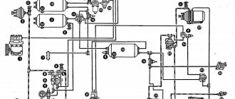
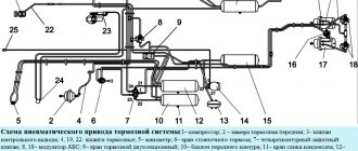
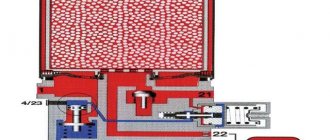
Rice. 1. Diagram of the pneumatic system: 1 - compressor; 2 - pressure regulator; 3 — air bleed valve; 4 - pressure gauge; 5 - drain tap; 6 — air cylinder; 7 - brake valve; 8 — pneumatic adapter; 9 - disconnect valve; 10 — connecting head; 11— pipelines.
The compressor works as follows. When the shift lever is moved, the intermediate gear meshes with the fuel pump gear and begins to transmit torque to the crankshaft. From the shaft, the reciprocating motion is transmitted to piston 8. When the piston moves downward, air from the engine suction manifold enters the cylinder through the connecting pipe and suction valve. As the piston moves upward, the inlet valve closes and compressed air enters the pneumatic system through the discharge valve and pipelines.
When the air pressure in the cylinder reaches 7.3 kgf/cm2, the pressure regulator is activated and disconnects the compressor from the air cylinder. The air from the compressor enters the atmosphere through the regulator without back pressure, and due to this the compressor is unloaded. When the pressure in the cylinder drops to 6.6-6.9 kgf/cm2, the regulator reconnects the compressor and compressed air enters the cylinder.
Compressor maintenance involves periodically checking its tightness and fastening. Removal of carbon deposits from the surfaces of the head, piston, valves and air channels should be carried out after 960 hours of operation. At the same time, check the tightness of the valves.
Rice. 2. Compressor: 1 - intermediate gear; 2 — power lever; 3 - cylinder head; 4 - discharge valve; 5 - suction valve; 6 — piston rings; 7 - cylinder; 8 - piston; 9 — piston pin; 10 — connecting rod; 11 - crankcase; 12— crankshaft; 13 — crankshaft bearing.
The pressure regulator is designed to automatically regulate the air pressure in the system within specified limits (6.7 to; -7.3 kgf/cm2), as well as purify the air from water, oil and solid particles.
The regulator is installed between the compressor and the air cylinder and is secured to the air cylinder using a fitting.
The regulator housing contains a filter element, a relief piston, and an air bleed valve with a check valve. Between the regulator body and the spring body there is a diaphragm assembly with valves. A spring is installed in the housing, acting on the diaphragm. The spring compression is adjusted with a screw. An outlet valve is mounted in the bottom cover, connected to the unloading piston using a rod with a spring.
Rice. 3. Pressure regulator; 1 - cover; 2 – exhaust valve; 3 - retaining ring; 4 — washer; 3, 13, 21, 24 — springs; 6 — unloading piston; 7 - filter element; 8 — body; 9 - shut-off valve; 10 - bushing; 11 - top valve; 12 — spring housing; - screw; 15 — nut; — dust cover; 17 - fitting; — protective nut; 19 — air bleed valve; 20— check valve; 21 — rod; 23 — exhaust pipe.
The pressure regulator works as follows. Air from the compressor is supplied to the cavity of the filter element. Next, the purified air passes through the channels in the housing into the cavity of the fitting and, pressing the check valve, enters the air cylinder through the connecting fitting. Since the sub-diaphragm cavity is connected through drillings in the body to the cavity behind the check valve, when the pressure rises, the diaphragm, under the action of compressed air, moves upward together with the bushing, compressing the spring. The movement of the diaphragm will continue until the valve seat, made in the bushing, rises all the way to the upper valve and thereby disconnects the unloading cavity from the atmosphere. When moving up, the shut-off valve opens and compressed air flows through the housing bores into the cavity above the unloading piston. Under the influence of the incoming compressed air, the piston moves down and opens the exhaust valve. At the same time, the compressor is unloaded, that is, air is released into the atmosphere through the open exhaust valve, while simultaneously blowing out the accumulated condensate. The pressure in the cavity in front of the check valve drops, and it closes under the action of a spring and compressed air pressure, preventing a decrease in pressure in the pneumatic system.
When the air pressure in the air cylinder decreases to 6.9-6.6 kgf/cm2, the spring moves the diaphragm and bushing down. As a result, the shut-off valve sits in the seat, blocking the communication of the unloading cavity with the cavity under pressure behind the check valve 20, and the upper valve I opens, connecting the unloading cavity with the atmosphere. At the same time, the unloading piston moves upward, closes the outlet valve and the compressor begins to supply air to the air cylinder.
The exhaust valve also serves as a safety valve. When the pressure in the pneumatic system increases to 8.5-9 kgf/cm2, the valve moves down and opens the outlet for compressed air to the atmosphere.
During operation, it is necessary to constantly monitor the pressure in the system using the pressure gauge readings, which should be in the range of 6.6-7.3 kgf/cm2. If the difference in pressure between turning on and off the regulator is more or less than the required value (0.4-0.7 kgf/cm2), then you need to disassemble it and repair faulty parts. Then set the pressure control limits.
Periodically (at least after 240 hours of operation) it is necessary to clean the filter. To do this, unscrew the four lower screws and remove the cover along with the unloading piston. Then, having removed the retaining ring and spring washer, remove the filter, wash it in kerosene, blow with compressed air and dry. At the same time during disassembly it is necessary
check the condition of the rubber parts. Reassembling the filter is done in the reverse order.
The brake valve is designed to control the trailer brake drive. The brake drive control is interlocked with the tractor brake control.
The valve consists of a body, a cover with a discharge channel communicating with the control channel through a spring-loaded double valve; a valve connected by a tie to the valve; diaphragms, etc.
The housing contains a diaphragm, a balancing spring, a pusher with an adjusting plate and a cam mounted on the shaft.
In the braked state, the inlet valve is open and the outlet valve is closed and compressed air from the air cylinder through the injection channel enters the control channel and from there into the connecting line and the trailer brake system.
When braking, the force from the brake pedal through the drive system (rod and lever) is transmitted to the shaft, which rotates together with the cam in the direction of decreasing the tension of the balancing spring. As a result, the diaphragm, under the influence of air pressure and the spring, moves to the right, closing the intake valve and opening the exhaust valve. Compressed air from the connecting line escapes into the atmosphere, as a result of which the trailer's air distributor is activated and the latter is braked.
Rice. 4. Brake valve: 1 - atmospheric valve; 2 — lever; 3 - dustproof valve; 4 - bolt; 5 – ball; 6 — clamp spring; 7 — body; 8 — return spring; 9 - cover; 10 - nut; 11 — discharge channel; 12 — inlet valve; 13 - gasket; 14 — control channel; 15 — exhaust valve; 16 - diaphragm; 17 — balancing spring; 18 — adjustment plate; 19 — pusher; 20 - cam; 21 - shaft.
Rice. 5. Pneumatic adapter: 1 - cuff; 2 - bushing; 3 - ring; 4 — return spring; 5 — body; 6 - cover; 7 — diaphragm; 8—disk; 9 - clamp; 10 - saddle; 11 - plug; 12 - pusher.
When braking, the opposite effect occurs. Under the action of the tension spring, the lever turns the shaft with the cam towards the compressed spring, the exhaust valve closes, and the inlet valve opens, and compressed air from the air cylinder enters the connecting line.
During operation, it is necessary to regularly monitor the tightness of the brake valve connections and the cleanliness of the outlet hole. After 960 hours of operation, you need to check the pressure value (7±0.3 kgf/cm2) at the outlet of the brake valve and adjust if necessary.
The pneumatic adapter allows you to attach a trailer with a hydraulic brake drive to the tractor. It is installed on the right side of the tractor on the cab bracket.
The pneumatic adapter consists of a body and a cover, between which a rubber-fabric diaphragm is clamped with a clamp. The return spring presses the disk with the pusher to the diaphragm.
A seat with cuffs and a bushing, in which a removable plug is installed, is attached to the body with two bolts. When the tractor is operating with a trailer, the plug is removed and the trailer brake master cylinder is installed in its place. Cavity A of the adapter is connected by a pipeline to the air cylinder, and control cavity B is connected to the connecting line.
When braking, the pressure in cavity B drops sharply, as compressed air exits the cavity into the atmosphere through the connecting line and the brake valve. Under the action of compressed air entering cavity A from the air cylinder, the diaphragm moves a disk with a rod, which acts on the piston of the trailer’s master brake cylinder and brakes the trailer.
When the brake is released, compressed air from the air cylinder enters the connecting line, and from there into cavity B. The pressure in cavities A and B is equalized. The diaphragm with the plate and rod moves under the action of the return spring to its original position, releasing the trailer.
During operation, it is necessary to monitor the tightness of the pneumatic adapter and its fastening connections.
A large air leak can be detected by ear, while a minor leak can be detected using soap suds.
A diaphragm that has lost its elasticity must be replaced with a new one. In this case, it is necessary to ensure that the flanges of the cover and body are smooth, without nicks or dents.
The disconnect valve is designed to turn on and off the trailer brake line. It is installed on the right rear cab bracket.
Rice. 6. Isolation valve: 1 - spring; 2 - plate; 3 - valve; 4 - roller; 5 — body; 6 — shift lever; 7 - pin; 8 - gasket; 9 - nut.
A valve is installed in the faucet body, pressed to the socket by a conical spring and a plate. The locking nut presses the spring against the plate.
When the trailer brake line is turned on, the shift lever is located along the valve body and air flows through cavity A, the open valve and cavity B to the connecting head. In this case, the air outlet hole into the atmosphere is closed.
When the trailer's pneumatic system is turned off, the lever rotates 90° and air from cavity B escapes into the atmosphere through a chute in the valve and a hole in the valve body. The pressure in the connecting line drops to zero, which makes it easier to disconnect the connecting heads.
During operation, it is necessary to monitor the tightness of the disconnect valve and its fastening to the rear bracket of the cabin.
If there is an air leak, the valve must be replaced.
The connecting head is designed to connect the pneumatic system of the tractor with the pneumatic system of the brake drive of aggregated trailers. It is attached to the isolation valve using a fitting.
The connection head consists of a body, a plate constantly pressed by a spring to a rubber seal, and a cover.
Rice. 7. Connecting head: 1 - plate; 2 — rubber seal; 3 - clamping ring; 4 — dust cover; 5—pin; 6 — body; 7 - spring.
When connected, the trailer head rod presses the plate and air flows freely from the tractor pneumatic system into the trailer pneumatic system. Rubber head seals prevent air leakage.
To connect the trailer to the pneumatic drive, open the cover, press the valve and, opening the disconnect valve, blow through the head to remove dust. After this, connect the heads and open the isolation valve.
When disconnecting the trailer, it is necessary to close the disconnect valve, disconnect the heads and cover them with dustproof covers.
If air leaks through the connection head, check the condition of the rubber O-ring and replace it if necessary.
A little about the MTZ-80, -82 tractors
Universal - row crop tractors MTZ-80 "Belarus", MTZ-82 "Belarus" have been produced by the Minsk Tractor Plant since 1974. The goal at that time was to create a tractor with a power of 75-80 hp. traction class 1.4.
In the 2000s, the above models were significantly modernized. The design of the tractor has received many changes. In particular, a new cabin with a deeply modernized engine was installed
Important All-terrain vehicle SR-21 Albatross for extreme travel on loose soil and snow
Production employees managed to achieve seventy percent unification of parts and assembly units, which is also important for the repair of MTZ 80, 82 tractors
Having received a slight rebranding, the tractors entered the market under the brands “Belarus-80” and “Belarus-82”, respectively.
The traditional layout of the MTZ-80 tractor is based on a semi-frame design with load-bearing housings for transmission units. The engine was front-mounted. The rear drive wheels have a significantly larger diameter compared to the front guide wheels.
All-wheel drive is an advantage of the MTZ-82 tractor.
The plant has developed several modifications of the above models, which differ from each other in the type, transmission ratios, engine starting method, attachment points for attachments, external design, type of rubber used, the amount of agrotechnical clearance, installation of systems that ensure operation on steep slopes. However, the repair of MTZ 80, 82 tractors differs slightly.
These are the most common tractors in the CIS,
being the owners of four-cylinder four-stroke engines of the 4Ch11/12.5 family (only models D-240 and D-243) produced by the Minsk Motor Plant with a semi-separated combustion chamber made in the piston, liquid cooling, a PZHB-200B pre-heater was installed on some of the engines.
Engine displacement is 4.75 liters. Rated power 59.25 kW (80 hp), in the original version 55.16 kW (75 hp).
When repairing the MTZ 80, 82 tractor, the engine is started using an electric starter (modifications D-240/243), or a PD-10 starting engine (modifications D-240L/243L), with a rated power of 10 hp, with start blocking when the gear is engaged.
The rigid suspension of the rear wheels on the drive axles has terminal connections, which allows you to continuously change the track width within the range of 1400-2100 mm. The front wheels with semi-rigid suspension are also adjustable within the range of 1200-1800, but in steps (100 mm increments).
Design features and components
Due to its phenomenal reliability, the Belarus tractor brakes use the simplest operating principle, which can not only immobilize the tractor itself, but also brake it with a loaded trailer, for example, where a pneumatic drive is installed.
The same can be said about any construction or agricultural work, where sometimes the quality of execution of assigned tasks depends on accurate and timely braking.
In order to hold heavy equipment motionless in one position, the Belarus tractor uses an operating principle that fixes the brake pedal using a special latch with teeth.
MTZ tractors are also equipped with piston compressors with single-stage compression and air cooling means designed for the pneumatic braking system of trailers.
A complete and detailed list of all parts that make up the brake system of the Belarus tractor:
Brakes and brake control:
1 - casing; 2 - ball; 3 - spring; 4 — connecting disks; 5 — pressure disks; 6 – fork; 7 - lock nut; 8 — adjusting bolt; 9 — pedal roller; 10 — mountain brake latch rod; 11 - spherical washer; 12 — left brake lever; 17 — mountain brake latch; 18 – thrust; 19 — glass lid.
Design and principle of operation
MTZ 82 brake system with mechanical drive and dry friction discs. Two working parts of the brakes are located in cylindrical housings on both sides of the transmission housing on the same axis of the driven gear of the main bevel gear with a differential on the drive shafts of the final drive of the tractor. By activating the mechanical drive, the brake mechanism stops the drive shafts of the left and right final drives of the transmission, stopping the movement of the machine.
Each brake element consists of a pair of cast-iron pressure discs and a pair of friction discs mounted on the sides. Friction discs are located on the splines of the drive shafts. The movement of the pressure disks is driven through a system of levers due to the rolling of expansion balls installed between the parts in inclined grooves. When you press the pedal, the balls roll in the grooves and run onto its rise, pushing the discs apart. The rotation of the drive gears is stopped as a result of the movement of the pressure disks, while the friction linings are connected on one side to the surfaces of the pressure disks and the other side to the stationary surfaces of the casing and cup. When you hold down the pedal, the balls run up to the rise of the groove as much as possible and rest against the shoulder, the friction discs are pressed against the surfaces, completely slowing down the rotation of the shafts. To ensure parallelism of the pressing planes, three grooves with balls are placed around the circle with a pitch of 120 ̊ or with five grooves with a pitch of 72 ̊. Return to the starting position is achieved by the force of three tension springs installed on a pair of pressure disks. The drive levers and pedals also move out of their working position due to the force of the spring.
Hydraulic and power regulator levers
Three distributor spool switch handles 27,28,29 are located on the right side of the control panel near the tractor windshield. Each lever has four positions. The levers are constantly in a neutral position, in which the working fluid supplied by the pump to the spools is passed into the drain cavity, and the working cavities of the hydraulic cylinders are locked by the spool and are in a fixed position. Moving the lever up corresponds to the “Lift” command - the spool opens the flow of oil into the cavities of the hydraulic cylinders for lifting. The first lower position corresponds to the “Lower” command. The second extreme position corresponds to the “Floating” hydraulic operating mode. The far right lever 29 of the standard distributor controls the hydraulic cylinder of the rear linkage, two free ones are intended for connecting additional equipment mounted with the tractor.
On tractors equipped with a hydraulic increaser of the grip weight of the GSV tractor, its control handle was located in addition to the three hydraulic distributor levers.
On the right side of the seat, on the same panel with the manual fuel supply handle, there is a position lock for the handle 43 of the power regulator and the lever of the regulator itself 45. The rearmost position of the power regulator lever is “raising the implement” when lifting the handle is held by hand. After lifting, the handle is released - it moves and is fixed in the “transport neutral” position. The intermediate position forward from the “transport neutral” is the “regulatory zone”. The extreme forward position is “forced lowering”. After lowering is completed, the handle automatically positions itself at the beginning of the control zone. The flywheel of the position regulator switching valve 52 is located under the driver’s seat and has three positions: the right position – “position control”; left – “power regulation”; medium – “off”. Handwheel 53 adjusts the correction speed of the power regulator. At the base of the driver's seat, closer to the right side, there is a leash 40 for controlling the fixation of the hitch in the transport position.
Tractor operating modes
Based on the nature of use, the tractor can perform work in two modes: transport and technological.
Transport control is characterized by the movement of the tractor when moving, both the machine itself and the transportation of goods in combination with trailed vehicles. As well as transport movement in a unit with technological trailed or attached equipment. In this case, control is limited to selecting and switching transport gearbox speeds and controlling the direction of movement by rotating the steering wheel using all driving skills.
MTZ 82 on transport work
The technological control mode is associated with the operation of the tractor in a unit with mounted and trailed devices, both in motion and stationary. Depending on the nature of the work, the technological equipment used in a unit with a tractor may either not require a drive or be driven by a tractor. In this mode, control is carried out in conjunction with the unit - the tractor and the machine used. That is, in addition to moving the tractor, the tractor driver needs to control the operation of the machine he is using. At the same time, the control must strictly comply with technological requirements ensuring safety, optimal performance and quality of the operation performed. When performing work in the unit, the following can be taken into account: the speed of movement with the specifically recommended gearbox for the operation, the processing depth, the cutting height, the rotation speed of the drive shaft, the working width and other parameters.
Technological operating mode of the tractor
For the qualified performance of operations when a tractor is coupled with this or that equipment, there are regulatory technological maps indicating all control parameters.
Performing a technological operation using a MTZ 82 tractor with a drive unit
The drive itself used with the tractor equipment can be carried out:
- Mechanically - power transmission by PTO rotation.
- Hydraulically - the pressure of the working fluid of the hydraulic lifting system.
- In rare cases, pressure is the air of the pneumatic system or the inertia created by the exhaust gases of a working diesel engine.
Management sectors
- Engine control – starting and stopping the diesel engine, regulating operating speed and fuel supply.
- Control of the tractor transmission in driving mode - selection of speed and direction of movement by shifting gears, control of the steering mechanism using turn signals, application of the main brakes and parking brake while moving and stopping the machine, use of all-wheel drive and differential locking of the rear axle.
- Transmission control in the operating equipment drive mode – selection of the power take-off shaft rotation speed, selection of the PTO operating mode “independent - synchronous”, activation of the PTO drive.
- The control of the hydraulic linkage system includes: control of the tractor linkage and its adjustment, the use of force and positional control when using soil-cultivating devices, the use of hydraulics to drive hydraulic units of equipment operating in conjunction with the tractor.
- Control of heating and ventilation devices for the tractor cabin, external and internal lighting and signal light devices.