Pneumatic brake system for PAZ-32053-07 and PAZ-4234 buses
The pneumatic system of bus brakes consists of a compressor, pneumatic devices and pipelines
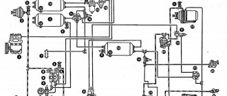
The diagram of the pneumatic drive of the brake system is shown in Figure 1.
In order to prevent failures of the brake system pneumatic devices from clogging during the initial period of operation, strainers can be installed at the inlet of the brake valve, dryer, four-circuit safety valve and modulators.
The PAZ-32053-07 bus uses a single-cylinder piston-type air-cooled compressor
The compressor is driven by the high pressure fuel pump drive gear.
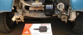
The PAZ-4234 bus can use both a two-cylinder (Fig. 2) and a single-cylinder compressor. In both cases, the compressor has an air-cooled cylinder block and a water-cooled cylinder head.
The compressor is driven by a belt from the crankshaft pulley. The belts are tensioned by a special mechanism.
Oil from the lubrication system is supplied through a hose to the compressor crankshaft channel and to the connecting rod bearings.
Ball bearings, piston pins and cylinder walls are splash lubricated.
The oil is drained from the compressor into the engine oil sump.
When servicing the compressor, check its attachment to the bracket, the pulley attachment, the tension of the drive belts (PAZ-4234), the attachment of the compressor cylinder head, as well as the condition and attachment of the compressor discharge tube, the coolant supply hoses to the cylinder head (PAZ-4234).
The compressor drive belt on the D-245.9E2 diesel engine is tensioned with a roller through the tension mechanism.
Before tensioning, loosen the tension roller shaft locking bolt and the adjusting screw locking nut. Then, by rotating the nut on the adjusting screw, move the screw along with the tension roller.
It is recommended to clean the compressor pistons and valves from carbon deposits once a year during seasonal maintenance, but no more than after 100,000 km.
Signs of a compressor malfunction are: the appearance of noise and knocking in it, excessive heating (more than 190 ° C), increased oil content in the condensate drained from the air cylinders.
The cylinder head nuts should be tightened evenly in the order shown in Fig. 3.
The final tightening is carried out with a torque of (20-25) Nm.
It is allowed to simultaneously tighten the head nuts to the final torque.
Attention! Air leaks in the pneumatic brake system increase the operating time of the compressor under load and thereby reduce its service life.
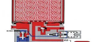
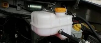
An air dryer with a built-in pressure regulator (Fig. 4) is designed to clean compressed air from moisture and contaminants, as well as to automatically maintain operating pressure in the pneumatic brake drive system.
The air supplied by the air compressor passes through the ring filter 2, where it is pre-cleaned from contaminants. There, the air is cooled, and part of the moisture contained in it is collected in the moisture separation chamber 4.
The air then passes through granular powder 1, where dehumidification occurs, to check valve 3, opens it and passes through outlet 21 to the four-circuit safety valve and then to the air receivers.
At the same time, an air receiver with a capacity of 5 liters is filled through the nozzle and outlet 22 to regenerate the drying element.
The air dryer has an electrically heated valve assembly, which is turned on when the key in the instrument switch is turned to position I. The electric heating turns on automatically at an ambient temperature of less than +10°C and turns off after heating to +30°C.
To monitor the normal operation of the dryer, you should check daily for the absence of condensation in the cylinder located after the dryer and monitor the tightness of the pneumatic drive of the brake system.
When condensation appears in the receivers, it is necessary to replace the filter element. If there is oil in the condensate, it is necessary to repair the compressor, since oiling the desiccant powder granules sharply reduces its service life.
Attention! To prevent brake system failures, the air dryer filter cartridge should be replaced once a year, regardless of its condition before the start of the winter period of operation.
Replacing the air dryer filter element is carried out in the following order:
- Clean the surface of the dryer from dirt.
- Loosen the threaded connection of the discharge pipe from the compressor and bleed air from it.
- Unscrew the filter element cartridge by rotating counterclockwise.
- Install the new cartridge, lightly lubricating the sealing gasket with oil.
- Tighten the cartridge by hand to a torque of no more than 15 Nm.
- Tighten the threaded connection of the discharge pipe.
The four-circuit safety valve (Fig. 5) is designed to divide the supply line into two main and two additional circuits, automatically turn off one of the circuits in case of damage and maintain a supply of compressed air in undamaged circuits, as well as to preserve air in all circuits in case of damage supply line.
The safety valve sections are adjusted in such a way that first the main valves of the service brake system and the door drive open (in Fig. 6, sections 21, 22, 24) at a bypass pressure of (607-637) kPa, and then the parking brake system valve opens ( section 23) at a bypass pressure of (656-686) kPa.
When section 21 is depressurized, compressed air is bypassed into it from section 23 through a specially built-in valve at a rate of at least 60 l/min.
After the bypass, the residual air pressure in the energy accumulators should be no more than 100 kPa (1 kgf/cm2).
Adjusting the valve eliminates the possibility of the bus starting to move when the pneumatic system is filled with compressed air to the point that ensures braking of the bus with the required efficiency, and also eliminates the possibility of releasing the parking brake system of the bus when the pressure level in circuit 1 of the service brake system decreases below the minimum level ─ less than 390 kPa (4 .0 kgf/cm2).
The manual parking brake valve is designed to control the spring energy accumulators of the parking brake system.
When the bus is moving, the crane handle is in the extreme forward position.
The crane device ensures that the handle automatically returns to the lower position when it is released. Only in the rearmost position is the handle fixed.
To release spring energy accumulators, the handle should be pulled out in the radial direction, while the handle freely returns to the “released” position.
The quick release valve is designed to speed up the release of air from the actuators by shortening the path traveled by the compressed air during release.
When the parking brake valve handle is in the “released” position, compressed air enters valve outlet I (Fig. 7), diaphragm 3 is pressed against the outlet seat in the housing; in this case, the edges of the diaphragm are bent and compressed air passes into terminals II and further into the energy accumulators.
When the pressure in terminal I drops, diaphragm 3, under the action of compressed air in terminals II, is torn away from the outlet seat in housing 1 and pressed against the seat in cover 2, thereby blocking the passage of air into terminal I.
Compressed air is released into the atmosphere through port III.
The brake valve is designed to control wheel brake mechanisms with a dual-circuit brake drive.
Terminals A and B of the valve (Fig. are connected to the air receivers of two separate circuits of the service brake drive.
From terminals G and D, compressed air flows to the brake chambers. Brake signal switches are installed in the crane body. From the outlet Into the air, after releasing the brake pedal, it exits into the atmosphere.
When servicing the brake valve, the attachment of the valve to the body base bracket is checked, the integrity of the protective rubber boot and the tightness of its installation are checked, and a diagnostic check is made for the correct operation of the valve.
In winter, if the tap freezes, to prevent damage to rubber and plastic parts, it is not recommended to warm the tap with an open fire. Warm air or hot water should be used for heating.
Due to the gradual disruption of the mobility of the brake valve pistons during bus operation, especially when water and oil get inside the valve on the friction surface, it is recommended to carry out a diagnostic check of the operation of the valve during TO-2.
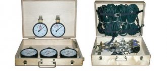
To do this, without removing the valve from the bus, you need to connect one pressure gauge to its upper and lower sectional terminals and, pressing the brake pedal, note the pressure difference.
The pressure difference should not exceed 0.025 MPa. If this condition is not met, the crane must be repaired.
It is recommended to carry out preventive disassembly of the brake valve once every 2 years to clean, lubricate and replace rubber O-rings and worn parts.
Assembling and checking the functionality of the brake valve
- Assembly should be carried out taking into account the following requirements:
— assembly must be carried out under conditions that exclude the possibility of abrasive dust, etc., coming into contact with the assembled parts.
— assembly of rubber parts must be done carefully to avoid the possibility of damage. The presence of cuts, scratches and other defects on rubber parts is not allowed.
— lubricate all rubbing surfaces of parts with a thin layer of CIATIM 221 lubricant. It is allowed to use AZMOL ZhT-72 lubricant.
- Before installing the upper piston, measure the distance “c” (Fig. 9) of the protrusion of the piston shank above the valve.
- Using the adjusting screw in the upper piston, set the distance α = (c + 0.8) mm and lock the adjusting screw.
- Install the upper piston and, if necessary, press it with a transport clamp.
- Assemble the apparatus with the base plate and lever.
- Install the adjusting bolt all the way into the lever so that there is no gap between roller 4 and pusher 5 (Fig. 10), fix adjusting bolt 2.
- Connect the tap to the compressed air system in accordance with the test diagram (Fig. 11).
- Move the lever three times until it stops (travel of at least 31.2 mm). When moving the lever there should be no jamming and it should quickly return to its original position.
- Supply air under pressure P11 = P12 = 0.75 MPa (7.5 kgf/cm2) to terminals 11 and 12.
Move the lever all the way and back three times.
The pressure in terminals 21 and 22 should vary from 0 to the pressure in terminals 11 and 12 and back.
- When the lever moves 4.7...7.4 mm (pusher stroke 1.9...3.0 mm), pressure should appear in terminal 21.
When pressure P21 = 0.05 MPa (0.5 kgf/cm2) is reached in outlet 21, the pressure in outlet 22 must be at least 0.025 MPa (0.25 kgf/cm2).
In this case, the lever stroke must exceed 4.7 mm (the pusher stroke must exceed 1.9 mm).
The advance of pressure growth in terminal 21 relative to the pressure growth in terminal 22 can be maintained over the entire pressure range, but not exceed 0.025 MPa (0.25 kgf/cm2).
The initial pressure surge in terminals 21 and 22 should not exceed 0.02 MPa (0.2 kgf/cm2).
- When pressure P21 = 0.3 MPa (3.0 kgf/cm2) is reached in terminal 21, the lever stroke should be (14.5-19.9) mm (pusher stroke (5.8...8.0) mm).
- When pressure P21 = 0.75 MPa (7.5 kgf/cm2) is reached in terminal 21, the lever stroke should be (21-27) mm (pusher stroke (8.4-10.8) mm).
- The total stroke of the lever to the stop should be (31.1-39.1) mm (pusher stroke (12.5...15.7) mm).
- When the lever moves smoothly, the pressure in terminals 21 and 22 after the initial jump should gradually increase, and when the lever is released, it should gradually decrease.
- Supply air under pressure P12 = 0.75 MPa (7.5 kgf/cm2) to terminal 12.
Move the lever all the way. In this case, in terminal 22 the pressure should change from 0 to 0.75 MPa (7.5 kgf/cm2).
- Supply air under pressure P11 = 0.75 MPa (7.5 kgf/cm2) to terminal 11.
Move the lever all the way. In this case, the pressure in terminal 21 should change from 0 to 0.75 MPa (7.5 kgf/cm2).
- Check the device for leaks. The valve must be sealed in any position of the lever.
The check is carried out with the lever released and pressure P11=P12 = 0.75 MPa (7.5 kgf/cm2) in terminals 11 and 12 and with the lever pressed all the way and pressure P = 0.75 MPa (7.5 kgf/cm2) in terminal 11. Air leakage in each case should not exceed 8 cm3 /min.
The brake valve drive is adjusted correctly if the full travel of the brake pedal, determined by the movement of the center of the pedal platform, is (105-117) mm.
In this case, the pedal platform should not touch the floor in the extreme pressed position, and the brake valve should be fully open. Pedal free play (18-25) mm.
The free play of the brake pedal is determined by the design of the brake valve.
If necessary (when removing and installing a tap), you can adjust the tap drive as follows:
— by rotating the fork along the thread of the rod, align the hole in the fork with the hole in the faucet lever, which is in a free state;
— unscrew the fork from the rod one turn and in this position install the fork pin, pin the pin and tighten the fork locknut.
The control outlet valve (Fig. 12) is designed for connecting control and measuring instruments to the drive for the purpose of checking pressure.
The bus has two valves: one on the right front and one on the right rear brake chambers.
To connect to the valve, use hoses and measuring instruments with a union nut M16x1.5. If necessary, the valve can be installed in the receivers by unscrewing the plugs from the bosses.
The condensate drain valve (Fig. 13) is designed for forced draining of condensate from the air receiver of the brake drive, and also, if necessary, for releasing compressed air from the receiver.
The condensate drain valve opens when you press pusher 3 up or move it in any direction.
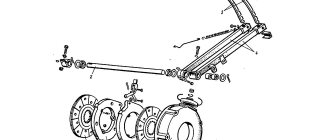
Brake chambers are designed to operate the wheel brake mechanisms.
The brake chamber with a spring energy accumulator is designed to activate the brake mechanisms of the rear axle wheels when the service or parking brake systems are engaged.
If the seal is broken and the pressure in the parking brake system circuit decreases, air from the cavity under piston 5 through terminal I will escape into the atmosphere through the damaged part of the pneumatic drive, spring 4 will release and the bus will automatically brake.
To mechanically release the rear wheels, it is necessary to unscrew screw 1 (Fig. 14) from the spring energy accumulator 68 mm from the outer surface of cylinder 2.
Attention! Before releasing the brakes, the bus should be secured against rolling away.
Attention! It is prohibited to disassemble the energy accumulator without using a special device, since there is a powerful spring inside it in a compressed state.
Attention! Before starting to operate the bus, the energy accumulators of the brake chambers should be brought into working condition; to do this, you need to fill the brake system with air, set the handle of the parking brake valve to the release position and tighten screw 1 until it stops (Fig. 14).
The auxiliary brake system consists of an engine brake 5 located in the engine exhaust pipe 1, a pneumatic cylinder 3, a control valve and pipelines.
The auxiliary brake system is activated by pressing and holding the valve button located on the driver's floor to the left of the clutch pedal.
In this case, compressed air through pipelines from the air cylinder of the brake system enters pneumatic cylinder 3, which, through lever 6, moves the damper in the engine brake and thereby blocks the exhaust pipe of the muffler.
Attention! Before applying the engine brake, release the fuel control pedal.
Attention! The auxiliary braking system (engine brake) only slows down the movement, preventing the bus from gaining speed on long descents. It is not intended to stop a bus and cannot be used for emergency braking or as a parking brake.
Attention! The engine brake is only used when driving on long descents with the gear engaged. In this case, a gear must be selected in which the engine speed does not exceed the maximum permissible (2400 rpm).
When servicing the pneumatic drive of the bus brake system, the tightness of the system as a whole and its individual parts is checked. Places of strong air leakage are determined by ear, and places of weak leakage are determined using a soap emulsion.
Air leakage in the service brake system is determined when the system is filled to operating pressure and the brake pedal is pressed.
In this case, the pressure drop should not exceed 0.05 MPa (0.5 kgf/cm2) for 15 minutes and 0.05 MPa for 30 minutes with the controls in a free position.
An air leak in the parking brake system is detected when the handbrake handle is in the “Unbraked” position. Air leakage from pipeline connections is eliminated by tightening or replacing individual connection elements.
To avoid breakage of the connecting bosses on pneumatic brake devices, the tightening torque of fittings, plugs, and nuts should not exceed (30-50) Nm.
To increase the reliability and reliability of the brake system, it is recommended to carry out preventive disassembly of the brake valve once every two years; brake chambers of rear and front brakes, safety valve; manual brake valve; quick release valve; replacement of a replaceable desiccant cartridge, regardless of their technical condition.
Faulty devices discovered during the control check must be repaired using repair kits and checked for operability and compliance with specifications.
The procedure for assembling and testing the devices is set out in special instructions. Their repairs are carried out by persons who have undergone the necessary training.
Attention! It is not allowed for pipelines to sag, touch them with parts and components that move and heat up during operation, or bend pipelines with a decrease in their flow area.
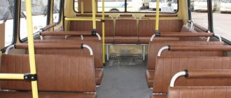
Design features and interior of Pazik
While modernizing outdated models, manufacturers installed on the PAZ 32054 an all-metal carriage-type body, accommodating 38 passengers, with 20 seats. On later models, the total number of seats increased to 42, and the number of seats increased to 23.
Semi-soft seats are not adjustable. All modifications are equipped with the same type of body with a variety of colors that have undergone anti-corrosion treatment. Body warranty for 6 years. For the convenience of passengers, the PAZ 32054 interior is equipped with two doors 725 mm wide; they open using a pneumomechanical drive device.
Bus windows with vents. There are hatches on the roof of the body that provide ventilation in the warm season. They are equipped with seals that prevent moisture from penetrating into the car interior during rains. Negative reviews about the PAZ 32054 interior are caused by the lack of a partition between the driver and the passenger compartment, and shortcomings in the layout of various switches on the dashboard.
An undoubted advantage of all buses is the accessibility of the engine from inside the vehicle, which allows the driver to carry out minor repairs without leaving the vehicle. The sprung driver's seat is also comfortable and can be adjusted horizontally and the back angle can be adjusted.
The bus floor has become more convenient for movement around the cabin thanks to a plywood covering and a height of 1965 mm. The body walls are lined with plastic.
At the customer's request, the bus can be equipped with an individual ventilation system and soft seats. For the convenience of passengers, an air conditioning system and stationary tables can be installed.
The PAZ 32054-07 modification with the same dimensions (length 7000 mm, width 2530 mm and height 2880 mm) and a diesel engine received a brake retardation system as standard. The bus is used on suburban and city routes, the turning radius is 7.5 meters. The fuel tank, as on the base model, is 105 liters.
The electrical circuit of the PAZ 32054 is double-circuit, with separate wiring for the passenger compartment and the bus engine, the electrical equipment is designed for 12V. The bus is heated using heaters from the radiator; three additional heaters are installed. They are connected to the engine starting liquid heater and the vehicle cooling system.
The popularity of the PAZ has always been due not only to its versatility, but also to the ability to quickly and inexpensively repair a vehicle. If repairs are necessary, spare parts for PAZ 32054 can be ordered directly from the factory or from GAZ group dealerships. Carriers value these vehicles for their affordable price and quick payback when operating on a busy transportation schedule. The price of PAZ 32504 buses, depending on the configuration, starts from 1,100,000 rubles.
Humble worker
In December 1989 at the Pavlovsk plant named after. (Nizhny Novgorod region, Pavlov) the PAZ-3205 small-class suburban and city bus model, which has become legendary, was launched into production during its “lifetime”. They can be found in every city in the country, because this four-wheeled worker has become the most popular bus produced in the country. In total, more than 30 modifications of this model have been developed, ten of which are mass-produced. One of them is the PAZ-32054 bus.
Despite its modest appearance, the nimble “groove” has proven its usefulness on city streets crowded with cars, on suburban routes with low passenger traffic, and as special transport in organizations, enterprises, and educational institutions of various profiles. And two PAZ-32054 automatic doors are much more convenient than one.
Design Features
The basic chassis has become common to the entire large family of new “grooves”. One of the significant features is the original pneumohydraulic, which made it possible to eradicate one of the main problems of the PAZ-672 - the insufficient efficiency of service brakes with a hydraulic vacuum drive. The steering mechanism has also changed - the use of a “screw-ball nut” type with a built-in hydraulic booster (from MAZ-5336) made it possible to reduce the number of flexible hoses by 60%, increasing the reliability of the unit.
The suspension did not go unnoticed: narrowing the spring track made it possible to reduce the turning radius, and extended front springs, together with the installation of correction springs, increased the smoothness of the ride. The body design of most versions was the same. This also applies to PAZ-32054, the photo of which, if you close your eyes to the additional door, looks like two peas in a pod to the photos of PAZ-3205. In 2013, after a slight restyling, the design of the headlights changed - they became rectangular.
Power point
Initially, it was decided to install two options of power units under the hood - gasoline and diesel. While gasoline engines (produced by ZMZ and MMZ) have proven themselves to be excellent, unforeseen problems arose with diesel engines. The domestic GAZ-542 and the Japanese Hino W04CT were considered as diesel units. The first diesel “Paziks” entered testing in 1987, but due to the complexity of the layout, the “GAZ” engine went out of the race almost immediately, and the expensive Japanese diesel was installed in the PAZ-32054 only on order from the beginning 90s
The direction of driving also developed. Back in 1987, technical specifications and technical documentation were prepared for a bus with propane gas-cylinder equipment, prototypes of which were built in 1987-1989. Development work on these machines was carried out jointly with designers from the PAZ, GAZ and ZMZ plants.
Now PAZ-32054 (technical characteristics are given below) has two types of execution:
- actual modification 32054 with gasoline engines produced by ZMZ;
- 32054-07 with gasoline MMZ.
The table shows the characteristics of each model:
Basic information, characteristics
- Manufacturer/manufacturer where the equipment is produced/manufactured. Pavlovsky Bus is a Soviet and Russian manufacturer of small and medium class buses. Located in the city of Pavlovo, Nizhny Novgorod region. Part of the GAZ group. Since 2005, bus production has been carried out by PAZ LLC, a 100% subsidiary of Pavlovsky Bus PJSC.
- Purpose. Rural bus.
- Class. Small.
- Body type. Carrier, carriage layout.
- Body resource. 5/10 years.
A little history
25 years ago, no one imagined that the PAZ-3205, which had just entered production, was destined not only for a bright life, but also for the opportunity to break the longevity record of its predecessor, the PAZ-672. The bus was not a consequence of the planned renewal of the model range. On the contrary, it was the result of the refusal to produce the more advanced PAZ-3203 model, the components for which were not supplied by related organizations. The designers of the plant found a compromise solution - they combined the new body with the old chassis, naturally, carrying out all possible modifications to the latter.
The first prototype of the PAZ-3205 was assembled in the summer of 1979, only a decade later it entered production. Despite the significant percentage of unification and external similarity with buses of the 3203 series, 3205 differed in interior layout and had a number of design differences in the body. A year later, the factory workers presented the predecessor of the modern PAZ-32054 - a two-door modification of the PAZ-32051.