The air doesn't go anywhere. Maybe there is some kind of safety valve or something else I need advice on.
Comments (24)
Vitaly Shebunin
Look for air leaks from the unloader to the safety valves
Alexander Karandaev
The same problem appeared after replacing the compressor. There are no air leaks anywhere
Ivan Svechin
So is it not pumping enough air or what? Resets early?
Nikolai Nikolaevich
We had this kind of garbage on a KAMAZ, then the air went through, pumped up and started dumping very often
Anton Ortaat
The air coming in is too hot.
Sergei Smertin
It pumps the circuit normally up to 8. It resets and closes after 20 seconds. The arrows are at 8. Shakes and resets again
Adis Ganiev
This is because the air in the receiver x valve is full, so reset
Sergei Smertin
I installed 3 unloading, the same thing, I don’t know what to do. Where to dig
Grigory Veretenik
Sergey, Vitaly Shebunin immediately pointed out the address of the malfunction - once again, with special care, check the line from the unloading to the four-circuit valve and from the unloading to the emergency brake release valve. Rationale: air is pumped into the system, the unloading is turned off and will not turn on until the air pressure in the system drops. But! If at the moment when the unloading is turned off, suppose there is a leak to the safety valve, the unloading will turn on because the air pressure in the line before the protection has dropped, the volume of the line to the safety valve is small, the compressor will quickly pump up air and the unloading will turn off again. To check my words, press the brake pedal if the unloading stops “sneezing” - V. Shebunin is right.
Sergei Smertin
Grigory, at what point should you press the brake?
Grigory Veretenik
Sergey, press when the unloading “sneezes”.
Sergei Smertin
Gregory, press and hold?
Grigory Veretenik
Sergey, no, just slow down. Using the brake, you will relieve pressure in the system and if the unloading stops working, but continues to pump normally, the unloading is working properly, but there is still an air leak. Or, rarely but sometimes, the four-circuit safety valve itself is faulty.
Sergei Smertin
Grigory Veretenik
Sergey, a lot of instructive information on repairing and diagnosing the KAMAZ brake system can be obtained on the channel 8 atmospheres of Shamil Magomedov on You Tube. By the way, there is something about “sneezing” in the Russian Far East.
Sergei Smertin
Grigory, turned off the unloading from the Kamaz system. It was powered by a simple compressor and connected 1 receiver to the output. The air has been pumped, the unloading gearbox has worked and is working as expected, which means that the problem lies further in the Kamaz system itself. Do you think this safety valve is clever? There are no leaks, I also pumped the system with a compressor.
Grigory Veretenik
Sergey, as I understand it, you connected the receiver directly to the unloading and the unloading worked. Sergey, read carefully what I write. Now you have created a kind of separate system, in which a supply of air of 20 liters is directly connected to the unloading. The unloading “feels” that it has air at its outlet and has started to work normally. If you connect the unloader to the KAMAZ system, on the way from the unloader to the four-circuit safety valve, there is only a line where I assume there is an air leak. In this situation, the entire KAMAZ system is filled and unloading does not “sneeze.” As soon as the entire system is filled to maximum pressure, the unloading should “sneeze” and the air from the compressor exits. The four-circuit valve stands there so that in the event of an air leak from the unloading to this valve, the entire system is disconnected from the supply line. As soon as it cuts off the system from the supply line, and the air leaves the tubes from the unloading and the emergency brake release valve (there is a leak somewhere in these places), the unloading will immediately begin to sneeze. To check my words, as soon as the unloading starts to “sneeze”, select the moment when the unloading “sneezed”, turn off the engine and after a couple of minutes unscrew the tube from the unloading to the four-circuit valve, if there is no air in the tube - I’m right, there is a leak to safety valve.
oops, I smoked it, I think
my compressor doesn’t know how to turn off, that’s the whole problem, it gets very hot because the air is constantly running, it’s hot, and there’s a big difference
You should probably solve problem number 2 first and then move on to problem number one
_________________ _________________
I’ll explain now, you just have to understand
Let’s say you don’t have any special unloading devices on your compressor with lifting valves. Then, in order for the compressor to “turn off”, it is necessary for a reset to occur followed by purging. At this time, the valve in the dryer tap switches the compressor to atmosphere, and it stupidly pumps outside without load. Imagine that you are inflating a wheel with your mouth up to 9 atm, and now imagine that you are inflating a balloon. While the compressor blows into the street, air from the purge receiver into the return line through the filter also blows into the street. When the air in the purge receiver runs out, the compressor continues to pump outside until the pressure in the system drops by some insignificant amount (this can last for several minutes - if there are no leaks in the system). If at this moment you press the brakes hard (i.e., create an air leak), the valve in the dryer switches the compressor from the street to the system, and the purge receiver is inflated first. And everything is new. It resets every now and then because control pressure is applied to the valve from the side of the purge receiver, but you don’t have it.
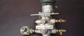
Discharge:
Look - on the right is a valve with a spring, this is the switch, there is also usually an adjusting screw there. And at the bottom left there is a relief valve, it is two-way (the piston is at the top on the same axis), there is nothing pressing on this piston, but it should. Only the lower plate opens the release from excess pressure. And also closes when this pressure drops. And the opening should continue precisely due to the upper piston (I circled it with an oval).
In short, use an additional receiver from a fire extinguisher, as Stas wrote somewhere, and you will be happy.
PS. By the way, freezing due to moisture is also possible, since there is no normal regeneration, the cartridge will not last long in this mode. Then it can be buggy in any way.
Well, wow, thank you, I’ll definitely copy this information to the topic by air in the Renault thread
current question now about the compressor there in the head for this there is a special piston on the side, as I understand it, it works from the pressure coming from the moisture separator from one of the holes, the valve in the moisture separator lowers and throws air there, and under pressure the piston moves and does what to the valves (or something something like that) so I want to connect this topic as it should and so that it also works as it should
if the compressor has a system that lifts the valves, then it should work, and not dry up from idleness and pump outward through an open valve in the moisture separator
I may be wrong, correct me if necessary - I can get to the removed compressor, unscrew its head, and show what we’re talking about, you can probably dig up a photo of the head on the Internet. I saw it somewhere
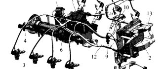
Design and principle of operation
The design of this mechanism includes such parts as:
- unloading piston and valve;
- air flow sampling plug;
- release type valve;
- spring mechanism;
- balancing device;
- adjusting screw;
- case;
- follower type piston;
- check valve;
- unloading mechanism saddle;
- cap;
- atmospheric findings;
- filter and pusher.
The flow of compressed air from the compressor system through the output of the control mechanism, filter elements and valves enters the receivers of the vehicle's pneumatic system.
The air passes through the channels under the piston part of the power unit, which is loaded by a spring balancing mechanism. At this time, the exhaust type valve connects the plane above the piston part.
Under the action of a spring mechanism, the inlet and discharge valves are closed, which allows the device that regulates the pressure level in the KamAZ system to be filled with air from the compressor.
Under the pressure of the air flow, the piston device overcomes the action of the spring and moves to the upper part of the system, the valve slams shut.
The compressed air lowers the piston mechanism back, and the valve opens again, and the compressed air flow passes through the terminals and penetrates into the environment along with the condensate accumulated in the working plane.
The unloading valve protects the mechanisms in the event of a failure of the safety device.
The compressor pressure level regulator operates unloaded, without backpressure.
Purpose
This element performs the function of removing oil and moisture, the presence of which can greatly affect the further operation of the compressor. By the way, it is the basis of any KamAZ brake system. It is through this that air is pumped under high pressure.
However, there are elements in the system that need lubrication. Therefore, during operation, air accumulates in the middle of the device. And since oxygen for the system is taken from the atmosphere, it contains a certain percentage of moisture. Its presence on highways is simply unacceptable. The slightest drops of water settling on the surface of the valves quickly damage the compressor. KamAZ will brake poorly. Also, the presence of moisture accelerates corrosion processes. Outwardly, these factors are extremely difficult to notice; this is only possible when the emergency air pressure lamp lights up on the instrument panel.
Therefore, the design includes a moisture-oil separator. A KamAZ truck equipped with such a device operates in any conditions, regardless of the air humidity outside. Passing through this device, it is cleaned of oil and dried from moisture. Only after this does it penetrate the receivers, where it is then directed to the actuators.
It is worth noting that the device cannot 100 percent purify the air of water and oil. Some percentage still remains in it. The receiver itself serves as an additional filter here. Air entering them from pipelines expands. At the same time, his temperature drops. And the remaining moisture condenses, settling on the walls of the tank. However, during long-term operation, experts recommend performing preventive maintenance on the system - manually opening a special bleed valve.
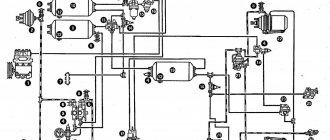
Description of the Kamaz pneumatic braking system
The basis for starting and stopping the air braking system is the circulation of compressed air. It is stored in special tanks. The circulation of compressed air is ensured by the operation of the compressor.
The brake operation diagram looks like this:
- Under conditions of increased pressure, a certain amount of air enters the compressor from the tank.
- After the brake system is activated, the operating torque is transmitted to the brake valve, which increases the pressure in the brake chambers.
- They are activated by a special lever, which is the key mechanism of the braking system.
- When the brake pedal is lowered, all parts return to their original position.
The backup brake works in a similar way. It is necessary to carry out maintenance of the brake system every 4 months.
Control and warning devices
The monitoring and warning device is a mechanism that serves to indicate a signal for increasing or decreasing pressure. The RDV adjustment is carried out using multi-colored lamps and a special signaling sound. This way the work of the main warning system is relieved. If there is a problem with its operation, it is enough to reset the settings and adjust the device again. Emergency alert works based on sensors installed in the brake system. If a problem occurs, the signal is immediately transmitted to the dashboard.
Device
Regardless of the type, the structure of these elements is the same. The filter-moisture separator is based on a metal body with a guide vane and a moisture release valve. There are also additional valves: a safety valve, which ensures uninterrupted operation of the device when moisture freezes in the radiator, and a return valve. The latter prevents pressurized air from flowing back to the compressor from the system.
It is worth noting that the KamAZ moisture-oil separator, depending on the type of design, has different condensate collection valves. On devices without an air pressure regulator, this is a diaphragm spool version. It opens due to air discharge when the regulator is activated. As for devices with RDV, their design includes one spring-type valve. It opens simultaneously with the pressure regulator.
Performance indicators
The main operating parameters of the KamAZ 65115 and 5320 brake system are presented below:
- brake pad size is 400mm;
- the area of the brake seals is 6.3 square meters;
- The brake is controlled using a pedal;
- the brake chamber is type 24;
- the mechanism that controls pressure differences has two cylinders;
- the maximum air supply in the device is 220 liters per minute;
- number of air cylinders - 5 pieces;
- The volume of air cylinders is 120 liters.
Repair of energy accumulator of KAMAZ vehicle
To find out how to check the energy accumulator on a KAMAZ, how to replace the KAMAZ energy accumulator, you should first remember that KAMAZ vehicles use several types of energy accumulators. Any energy accumulator includes three parts:
- The lower part is attached to the bracket related to the brake caliper using M16 studs.
- The middle part is made of an aluminum-based alloy and is connected to the part located below by means of a clamp with 2 bolts.
- The upper part, which is a glass made of steel, is attached to the part located in the middle with 8 M8 bolts.
Types of pressure regulators for Kamaz vehicles
There are several types of pressure regulators in the brake system of a truck:
- ball
- disc-shaped
- combined.
They differ from each other in that they have different air intake and exhaust valves.
There is also another classification of air pressure regulators in the pneumatic brake system:
- with sound insulation;
- without sound insulation.
On modern heavy-duty models, only devices of the first type are installed.
Varieties
Today, the KamAZ water separator can be of two types: with the RDV - a built-in air pressure regulator, or without it. These devices have the same purpose. However, their design is different. It is believed that devices with a built-in air pressure regulator provide more reliable operation of the pneumatic system. In addition, their design may include a radiator. Such elements use a combined type of air filtration - thermal and simply dynamic. The KamAZ water separator without a radiator has only the last type of drying. The element itself is a thin-walled ribbed tube, rolled into 5-6 turns.
How to adjust air pressure
In order to adjust the air pressure, it is necessary to install the vehicle on an inspection hole or a special platform for repair work.
Adjustment of the mechanism is carried out only when the power unit is turned off.
The whole process takes place in 3 stages: disassembly, adjustment and installation.
In order to dismantle the regulator, you need to unscrew the lock nut and turn out the adjusting screw. This will help loosen the counterbalance type piston springs. After this, use a special socket wrench to pull out the spring device, unscrew the protective cover and remove the sealing collar.
In order to remove the muffler, you need to unscrew the fasteners from the bottom of the cover and pull out the filter element. Then remove the 2 o-rings and the relief piston. After dismantling, it is recommended to wash all parts with clean gasoline.
After these steps, you should install the regulator on a special test stand and connect the device according to the diagram given in the user manual.
After connection, it is necessary to apply compressed air at a pressure of at least 1.4 MPa to the terminals 3 times.
If the limits of the regulated pressure exceed 0.8 MPa, you need to use a bolt to adjust the pressure level to the required limits.
Upon completion of the adjustment, you should check the level of pressure on and off the regulator 3 times, after which you can lock the bolt.
energy accumulator ZIL-KAMAZ
ENERGY ACCUMULATOR DISK ASSEMBLY WITH ROD FOR KAMAZ
Brake chambers of the rear wheels with spring energy accumulators are designed to activate the brake mechanisms of the rear wheels when the service, parking and spare brake systems are engaged.
energy accumulator
Only a highly qualified mechanic should disassemble, inspect, clean and lubricate parts of cylinders with a spring energy accumulator in a workshop using a special device in compliance with safety measures.
Remember that a strong spring is compressed in the cylinder; if you disassemble the energy accumulator incorrectly and carelessly, you can get injured
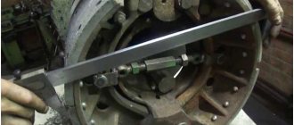
Assembling and disassembling the brake chamber
. Place the brake chamber on a level table and, loosening the lock nut 28, but without removing it, unscrew the fork 29. Then supply air under a pressure of at least 0.5 (5 kgf/cm2) into the cavity of the spring energy accumulator. Unscrew the clamps 30 securing the drain tube 12* and remove it.
Unscrew the bolts 31 securing the clamps 32 of the camera body and carefully, holding the housing 1 with your hand, remove the clamps 32, remove the housing 1 assembled with the rod, spring, support disk and cap. Remove membrane 16
Then, compressing the spring 20, unscrew the fork lock nut and remove the support disk 17 assembled with cap 2.
energy accumulator
Release the air from the energy accumulator and secure it in a vice with soft jaws by the flange-cover 14 upwards.
On-1+, heat it with a heating device to a temperature of 200 C and unscrew it with a special socket wrench. Re-introduce air into the energy accumulator under a pressure of at least 0.5 MPa (5 kgf/cm2).
Insert a special split mandrel, model I 804.00.008, into pusher 4 and, pushing bearing 13 down with it, remove the piston.
Bleed the air from the energy accumulator. Turn the energy accumulator over in a vice at 180a and unscrew the release screw 9 with a special socket wrench (Fig. 8-1 b) (see Fig. 8-15). Then remove the energy accumulator from the vice and, turning the flange cover down, remove the s-piston 4 thrust ring 27 of the bearing, bearing 13 and ring 25.
To further disassemble the energy accumulator, it must be installed in a special device • model P 804.33.004 (Fig. 8-17) and the power spring 8 must be compressed with the screw of the device.
Then unscrew bolts 23 with a spanner wrench, holding nuts 24 with another wrench.
After this, being careful, unscrew the screw of the device, and remove cylinder 7, power spring: 8 and piston 4. energy accumulator
energy accumulator
Warning. It is strictly forbidden to unscrew bolts 23 securing the energy storage cylinder outside the device.
On the surface of the hulls. parts are not allowed to have cracks, hairlines or other defects visible to the eye. Parts must be cleaned of rust and burnt marks.
All rubber parts must be replaced with new ones.
For assembly, install the flange-cover 14 on a special device (see Fig. 8-17) and insert the piston 4 assembly into it. Next, install the power spring 8 with a tapering loop to the piston and cover it with cylinder 7 so that the drain pipe pipe is located in the middle between the bosses of the flange-cover 14.
Compress the spring 8 with the screw of the device and secure the cylinder 7 to the flange-cover with bolts 2 and nuts 24. Unscrew the screw of the device, remove the energy accumulator from it and secure it in a vice by the flange-cover 14.
tighten the brake release screw 9 with a special key, having previously lubricated it with graphite lubricant VNIINP-232, GOST 14068-79. Turn the energy accumulator over in a vice by 180 degrees, supply air to the energy accumulator under a pressure of at least 0.5 MPa (5 kgcm2) and install it in piston 4 (see Fig.
8-15) ring 25, upsetting it with a mandrel, needle bearing 13 filled with CIATIM-221 lubricant, and thrust ring 27, oriented with its chamfer upward.
energy accumulator
Release the air from the energy accumulator and unscrew the brake release screw 9, while observing whether the pusher 4 is supplied. After normal release of the brake is ensured, you need to tighten it again with a torque of 40...50 N.
Re-inject air under a pressure of 0.5 MPa into the energy accumulator, visually check the correct installation of the thrust ring 33, put the rubber sealing ring on the pusher 8, apply a drop of anaerobic sealant to its threads and screw it into the piston 4 with a torque of 40-50 Nm.
Add oil to the energy storage chamber
You will need to add about 100-150 grams of oil to the energy storage chamber. To do this, you will need to find some kind of syringe for pumping oil. We will pump oil through the drain tube.
The poured oil will lubricate the walls of the energy accumulator piston during operation, and will lubricate the piston cuff and prevent the cuff from drying out, thereby increasing its service life.
Malfunctions and repairs
Main malfunctions and repairs of the regulator:
- If air leaks from the atmospheric outlet, the valve body must be cleaned or the defective valve and O-ring must be replaced.
- The device has stopped switching the compressor to idle mode. This problem can be caused by a clogged channel, pinching of the piston, or damage to the cuff. It is recommended to clean the valve, conduct an external inspection of the cuff and, if necessary, replace it with a new one, and also update the piston.
- The regulator stopped switching the compressor to the mode of filling the system with air. This malfunction is associated with clogged atmospheric orifice and intake valve, damaged spring, worn O-ring, tight piston part and worn valves. It is necessary to conduct an external inspection of the entire system for damage and defects, and if necessary, replace failed spare parts.
- Air leakage through the outlet into the atmosphere can be eliminated by replacing the filter element.
- When there is no supply of compressed air flow to the brake system of a vehicle, it is necessary to clean the check valve from accumulated contaminants or replace it if worn.
- If there is a small shaft between the on- and off-pressure level of the regulating device, damaged cuffs and rings should be replaced, valves and seats should be inspected and cleaned.
All repair work is carried out only with the engine switched off.
Energy accumulator MAZ device and functions
Trailer brake control valve
Most trucks, including MAZ and KAMAZ, are equipped with a braking system powered by a pneumatic drive. The operation of the units is ensured by creating force in the brake chamber. As a result, the pads in the drum are released. But this option is only suitable for service brakes that are used when driving with the engine running. For the operation of the reserve and parking braking systems, a MAZ spring energy accumulator is required.
In this article we will tell you about the operating features, design, and functions of the units.
The principle of operation of the MAZ energy accumulator
A modern device stores the energy that is required to operate car brakes in the absence of a source of compressed air, that is, when the engine and compressor stop.
The durable KAMAZ MAZ energy accumulator has a small compressed spring in which energy is stored.
If necessary, it expands as much as possible, forcing the brake mechanisms in the wheels to work. First, the spring is compressed due to the force of air supplied by the pneumatic system.
When using a handbrake, a spring creates a slight force to hold the shoes on the drum.
If malfunctions occur, the MAZ energy accumulator is capable of providing emergency braking.
MAZ energy accumulator - design and functions
The spring-pneumatic unit consists of:
- Cylindrical body made of durable metal;
- Powerful coil spring;
- Piston in the form of a cylinder with a pusher;
- Release screw and small nut.
There are fittings in special chambers of the MAZ energy accumulator. The device is installed on the brake chamber so that the piston pusher is opposite the hole in the chamber. To effectively release air when the spring is compressed, a drain tube is provided.
The type of mechanism is indicated by a fractional number, where the first digit indicates the effective area of the membrane in the brake chamber. For example, a MAZ 24 energy accumulator.
The most common system malfunctions are damage to the housing, wear of the diaphragm, and breakage of the lid bots. It is necessary to regularly inspect the mechanisms for breakdowns and, if necessary, repair or replace parts.
The cost of restoring a car with faults in the brake system is significantly higher than the price of a MAZ energy accumulator.
Therefore, if you need to have your truck repaired, contact our company. We will help you buy MAZ spare parts at the best price. We also organize delivery of parts to any city in Russia.
Do you still have any questions? Call the company office +7 (495) 223-89-79. Qualified specialists will help you choose a high-quality MAZ energy battery of the required model.
Reviews and prices
The average cost of the Russian Far East is 4,500 rubles.
Mikhail, 36 years old, Izhevsk: “I have been working as a KamAZ driver for 6 years. During the entire period of operation, the air pressure regulator in the pneumatic system failed several times. On average, repairs take about one to two days. In order for the mechanism to break down less often, I recommend using high-quality fuel.”
Alexander, 49 years old, Lipetsk: “I work in a service center. Cars are often brought in for repairs with a non-functioning air pressure regulator. This mechanism fails if maintenance is not carried out on time and the oil in the system is not regularly changed. I also recommend cleaning the filters at least once a month.”
Evgeniy, 53 years old, Voronezh: “I work at KamAZ 45143. The regulator failed only 2 years after the start of operation of the vehicle. First, an air leak began, and then the device stopped switching the compressor to the desired operating mode. I did the repairs myself according to the instructions, no difficulties arose.”
Konstantin, 46 years old, Leninsk: “In order to repair the regulator, I recommend using a special device that helps adjust the pressure level. Before connecting equipment to this device, it is required to carry out an external inspection of the regulator for the presence of any damage or defects.”
Peter, 50 years old, Krasnodar: “I have repaired the regulator at KamAZ 3 times already. The cause of failure is always clogged filter elements and damaged cuffs. In order to avoid malfunctions, I recommend changing the O-rings once every 3 months and regularly carrying out vehicle maintenance.”
How do you like the performance and durability of the air brake system? Are you satisfied with its service life?
We also recommend paying attention to the pneumatic valve, solenoid valve and damper mechanism.
If a malfunction is detected, we recommend contacting a service center to diagnose and understand the problem. An independent solution can lead to more serious damage.
Where can repairs be made?
- 1) On site (on-site visit of a specialist within Moscow and Moscow Region)
- 2) Service center in Podolsk (Pleshcheevskaya street, 30B)
- 3) Service center in Moscow (Skotoprogonnaya st., 33A, building 1)
Timely troubleshooting will save you from additional waste and major repairs.
bad blood pressure | Topic started by: Miyuki
Salute to all KAMAZ drivers! The following problem appeared: on the KamAZ it became difficult to pump air into the system, up to 5.5 at idle it pumps normally, and above that it is already difficult and very slow.
Andrey (Coronis) look at the cut-off valve. Although most likely the compressor is “ales kaput”
Olexiy (Fasih) Possibly different, this happened to me because of the valves (in the compressor)
Evgeny (Quon) definitely for the compressor
Alexander (Yoshio) look at all the tubes, maybe there’s a break, I had it like that until 5, it shakes and that’s it, I’ve been looking for where the hiss is for a long time
Mister (Tallulah) is not a pipe, It’s a valve, or rather a discharge valve, It’s being bent by the bastard
Anatoly (Gaetano) guys, I have a problem, help, it pumps air only at high speeds and ate, ate, two presses of the brake pedal, and the whole car releases the brakes! what to do??
Niaz (Sudhi) what is the cost of the compressor?
Artur (Wambua) press the outlet of the air compressor through a rag with your thumb, if you don’t hold the pressure, then the RDV is fucked!
Arthur (Wambua) I came across this. I installed 3 new compressors and no show off. there was a reason for everything in the Russian Far East
Seryoga (Lilia) please tell me yesterday I started constantly relieving the pressure of the soldier EVEN WITH 2 GLASSES IT WORKS. today I did it directly, the compressor barely pumped up 6, what could it be
Evgeny (Quon) The condensate in the tubes is frozen, most likely, if the copper tubes take a blowtorch in your hands and go and warm them up! And pour dehumidifier into the alcoholic, everything should be fine! )
Kamil (Alexandrina) The new Kamaz pumps up to 5'5. I changed the compressor, changed the hose pump, changed the triple counting valve. It doesn't pump. One of the receivers is humming.
Ruslan (Andongwisye) Salute to all drivers! Such a problem, it pumps air up to 6 atmospheres, then, well, not like, before and after the soldier it pumps the same way, maybe someone can tell me. Thank you in advance!
Andriy (Shayla) Guys help solve this problem on KAMAZ, the lower scale pumps air 8 and the upper one 4, so in just over an hour you can pump nothing.
Ilfat (Pravin) Could the compressor pump poorly due to the water separator filter? if it is clogged for example.
Sasha (Wehilani) Hello everyone. The problem is this: the compressor is working, I checked all the tubes, but the air is not pumping, what should I do?
Sasha (Wehilani) Hello everyone. The problem is this: the compressor is working, I checked all the tubes, but the air is not pumping, what should I do?
Dinar (Anoushig) Sasha, isn’t he pumping anymore?
Ranis (Shakambhari) Dinar, I have such a situation, I installed a new compressor, it pumps 1 point and drives oil! what's the matter? please tell me if you know!
Malfunctions of pneumatic drive power supplies
When servicing the pneumatic drive of the car brakes, you must first make sure that the system is tight. Particular attention should be paid to the tightness of connections of pipelines and flexible hoses, since this is where air leaks most often occur.
Places of strong air leakage are determined by ear, and weak ones - using a soap emulsion.
Air leaks from connections of pipelines and brake system devices are eliminated by tightening them, and leaking pipelines and flexible hoses are replaced. It must be remembered that on cars manufactured since March 1986, pipeline connections are sealed using rubber rings, so the tightening torques of the fittings should be less (Table 1).
If the air cylinders of the brake pneumatic drive are not filled and the pressure regulator vents air into the atmosphere, there may be several reasons:
— the pipeline between the regulator and the safety valves is blocked;
- the pressure regulator is faulty - most often the filter element in it is clogged with oil or ice crystals.
pipeline diameter, mm.
Tightening torque, kgcm
If the air tanks fill slowly and the air pressure does not reach the nominal pressure, then either the compressor or the pressure regulator is faulty. A malfunction of the compressor cylinder-piston group is also indicated by an increased oil content in the condensate.
Often the cylinders of a separate circuit are poorly filled. The air in each circuit of the brake system passes through a section of its “own” safety valve. Probably, the safety valve does not allow air into the cylinder or the air supply line to this circuit is clogged. It is also possible that the standard two-pointer pressure gauge is faulty.
Operating rules
This item requires minimal maintenance during use. But we will note several features, knowledge of which will significantly extend the life of the moisture-oil separator. First, you need to install it correctly. The drain hose must point straight down. Thus, the collected condensate will be directly and unhinderedly discharged outside. If the fitting is moved to the side, even at high pressure some moisture will remain, which will provoke corrosion processes inside the elements.
Also, do not forget about the tightness of the system. If you install a used separator, it is advisable to purchase a repair kit and change the sealing elements. Otherwise, this device has high reliability and operational efficiency, protecting the rubber diaphragms of the brake chambers from the harmful effects of oil, and the valves from corrosion and freezing in winter.
It can only be faulty if it is depressurized. For example, if he began to “poison” the air frequently. In this case, the problem is solved by purchasing a repair kit. It includes a set of springs, rubber O-rings and cuffs. By the way, if the latter malfunctions, the device constantly “hisses”, letting some of the air out under pressure.
Malfunctions of pneumatic drive power supplies
When servicing the pneumatic drive of the car brakes, you must first make sure that the system is tight.
Particular attention should be paid to the tightness of connections of pipelines and flexible hoses, since this is where air leaks most often occur.
What pressure is considered nomative?
The quantity and degree of compression of air pumped into the cylinder must be as indicated in the specialized table attached and the instruction manual. On a metal plate attached to the cabin doorway. If the data is unreadable or the plate is missing, make sure that you always have a printed memo in your glove compartment, which indicates what pressure should be in the tires of your Kamaz.
The table shows the relationship between tire size and standard pressure. It also depends on the axle load. Different models have different pressures. Thus, the lightweight KamAZ 43118 rides on wheels with less inflation than the heavy truck KamAZ 65115. But in some cases it is even recommended to artificially lower the tire pressure.
Malfunctions of the service brake system
Ineffective braking of the car when you press the brake pedal occurs if the brake valve drive is out of alignment or the two-section brake valve is faulty. If, during braking, the pressure in the brake chambers is nominal, then the wheel brake mechanisms are misaligned or faulty.
If, when braking with the service brake, the pressure is below normal only in the brake chambers of the front axle, then either the lower section of the brake valve or the pressure limiter is faulty. If the pressure in the brake chambers is normal, but braking is not effective, then the stroke of the brake chamber rods is greater than normal, or, for example, the brake linings are oily.
When you press the brake pedal, the braking of the wheels of the rear cart is ineffective or does not occur at all (the front wheels brake normally). In the pneumatic part of the drive, the upper section of the brake valve or the brake force regulator may be faulty. In the mechanical part, the brake mechanisms or the drive of the brake force regulator lever are faulty or misaligned.
If, after releasing the brake pedal, all the wheels of the car do not release the brakes, then the two-section brake valve is faulty (the pusher or the upper piston is jammed). It is possible that the brake valve drive is out of adjustment (there is no free play of the brake pedal).
If air does not come out of the rear brake chambers after releasing the brake pedal, the brake force regulator or the upper section of the brake valve is faulty. These malfunctions lead to a delay in the release of air from the front brake chambers. If, when releasing the brakes, air is not released only from the front brake chambers, then the pressure limiter or the lower section of the brake valve is faulty.
Malfunctions of the pneumatic drive of the parking brake system and the emergency brake release circuit
If, when the parking brake is turned off, the wheels of the rear trolley do not release the brakes, then the reason for this may be a malfunction in the parking brake valve, in the accelerator or dual-line valves, or in energy accumulators. It is possible that one of the pipes in the parking brake circuit is clogged, frozen or pinched. In the parking brake valve, a breakdown of the guide plastic plate or unreliable attachment of the rod to this plate leads to the parking brake not braking. In an accelerator valve in winter, the most likely cause of non-release is the freezing of condensate in the cavity above the piston.
If, when moving the parking brake valve handle, one of the energy accumulators does not work, then mechanical damage to this device is possible: dents in the body or sticking of the pusher. It is also possible that the pipeline through which air is supplied to an inoperative energy accumulator may become clogged.
If the brake chamber rods come out when the energy accumulators are turned on, and the car does not brake effectively enough, then it is necessary to check the stroke of the rods (it should not exceed 40 mm) and the serviceability of the wheel brake mechanisms. The brake pad linings must not be worn or oily.
The most common malfunctions in the parking brake circuit, as in the entire pneumatic drive, are compressed air leaks due to malfunction of the sealing rings and cuffs. It is important to determine the cause of the leak and find the faulty device.
Air leakage from under the parking brake valve handle when the brake is released is caused by a leaky rod seal in the guide. This seal fails the fastest because the rod reciprocates and rotates, and the diameter of the o-ring is small.
The cause of air leakage from the atmospheric outlet of the parking brake valve is not always a leak in the seals in the valve itself. The two-wire trailer brake control valve may be faulty. How to identify a faulty device? Fill the pneumatic drive with compressed air, turn on the parking brake, disconnect the control line tube from the valve; if air leakage from the atmospheric outlet continues, then the parking brake valve is faulty; If a leak is observed from the disconnected control line, the trailer brake control valve is faulty.
If air leaks from the atmospheric outlet of the accelerator valve both during braking and when releasing the parking brake, the sealing ring of the atmospheric outlet of the valve is leaking. Air leakage through the atmospheric outlet of the device when braking with the parking brake is caused by loss of tightness of the intake valve, and when releasing the brake, loss of tightness of the exhaust valve. In the latter case, the rear wheels are not released. Sometimes air leakage through the accelerator valve is observed when the parking brake is applied and the brake pedal is pressed at the same time. In this case, one of the energy accumulators is faulty - air from the brake chamber goes through the seal of the pusher pipe into the energy accumulator and then through the accelerator valve into the atmosphere.
Principle of operation
Compressed air from the compressor through terminal 1 of the regulator, filter 3, channel D and check valve 10 flows to terminal 111 and then into the air cylinders of the pneumatic drive. At the same time, through channel G, compressed air passes through cavity B under the balancing piston 9, which is acted upon by spring b. The outlet valve 4, connecting the cavity E above the unloading piston 12 with the environment through the outlet P, is open. The inlet valve 11, through which compressed air is supplied from the annular channel into the cavity E, is closed under the action of its spring in the same way as the unloading valve 2.
scheme
This state of the regulator corresponds to filling the air cylinders with compressed air from the compressor. When a certain pressure is reached in cavity B, the piston 9, overcoming the force of the spring 6, rises upward. Valve 4 closes under the action of the pusher, inlet valve 11 opens, and compressed air from the annular channel enters cavity E.
Under the influence of compressed Air, the unloading piston 12 moves down, the unloading valve 2 opens, and the compressed air from the compressor through outlet 4 exits into the environment along with the condensate accumulated in the cavity. In this case, the pressure in the annular channel drops and the check valve 10 closes. As a result, the compressor operates in unload mode without backpressure.
system pressure adjustment
When the pressure in port 3 and cavity B drops to a certain value, piston 9 moves downward under the action of spring b, Inlet valve 11 closes, and outlet valve 4 opens, communicating cavity B with the environment through pin 11. Unloading piston 12 rises upward under the action of a spring , valve 2 closes under the action of its spring, and the compressor again pumps compressed air into the cylinders.
Unloader valve 2 also functions as a safety valve. If the regulator does not operate at a pressure of 0.8 MPa (8.0 KGS/SMZ), then at a pressure of 1.0–1.35 MPa (10–13.5 kgf/cm?) the valve will open, overcoming the resistance of its spring and the piston spring 12 The opening pressure of valve 2 is adjusted by changing the number of washers under the spring.
terminal for tire inflation
The pressure regulator has an air bleed valve, for example, for inflating tires, closed by cap 15. When screwing on the hose fitting for inflating tires, the valve is recessed, allowing access to compressed air into the hose and blocking the passage of compressed air to terminal 11. Before inflating tires, the pressure in the air cylinders should be lowered to the pressure corresponding to the activation of the regulator, since during the unloading mode of the compressor operation, air sampling is impossible.
Regulator malfunctions
The main malfunctions of the regulator are wear of rubber seals, cuffs, and rings.
regulator filter
There are four main malfunctions that lead to disruption of the brake systems:
- malfunction of the protective valves, - clogging or leakage of receivers, pipelines and hoses, - piston rings and sensors are not working properly, - compressed air leaks.
In order to prevent possible malfunctions in the KAMAZ brake system, it is necessary to timely check the operation of its systems. This can be done once every two years. So, below is a list of possible malfunctions of the KAMAZ brake system and ways to eliminate it.
There is a lot of oil in the pneumatic system.
Wear of piston rings. Remedy: replace the compressor.
Receivers of circuit 1, 2 and 3 are not filled with air.
Cause: The supply tubes are clogged. Remedy: simply blow out the tubes, and if foreign objects are found there, remove them. Cause: The safety valve is broken. Remedy: change the valve.
Pneumatic system receivers fill very slowly or do not fill at all.
Cause: Tubes, hoses or adapter and connecting equipment are not tightened sufficiently. Remedy: Tighten the places where the parts are connected, if necessary, replace uncorrected parts. Reason: the receiver or device is not hermetically sealed. Remedy: change the receiver, device. Cause: The air supply hoses and tubes are damaged. Remedy: Replace hose and tube assemblies. Cause: Compressor performance is low Remedy: Check the compressor if it needs to be replaced. Reason: presence of dents on the surface of the air outlet or air supply bosses. It is noticeable to a large extent that the surfaces are not perpendicular to the axes of the holes in the threads. Remedy: sand out small nicks and dents. Eliminate the problem of non-perpendicularity.
In the receivers of circuits 1 and 2, increased or decreased pressure is observed while the pressure regulator is operating.
Cause: The pressure regulator is not adjusted correctly. Remedy: make adjustments using the adjusting screw, if necessary, replace the regulator. Cause: broken 2-pointer pressure gauge. Remedy: replace the pressure gauge.
The car brakes poorly or there is no braking when the brake pedal is pressed.
Cause: Compressed air leak. Repair air leak.
Poor vehicle braking or lack of braking.
The cause is clogged circuit 3 hoses or tubes. Remedy: clean the tubes and then blow them with compressed air. If necessary, replace it. Reason: Spring energy batteries do not work. Remedy: replace the spring energy accumulator and brake chamber. Cause: The relay valve is faulty. Remedy: Replace faulty parts. Reason: increased rate of stroke of the brake chamber rods. Remedy: adjust the stroke of the rods