Category: KAMAZ
- The concept of KamAZ ignition
- Reasons for adjusting the ignition on KamAZ
- Install the ignition on KamAZ
- Ignition installation for KamAZ Euro-2
- Ignition installation KamAZ Euro-3 fuel injection pump Bosch
- Installation of ignition on KamAZ fuel injection pump BOSCH
- Is the injection angle adjusted correctly?
If unforeseen situations arise with the operation of the truck, sometimes it becomes necessary to independently set the ignition on the KamAZ to solve the problems that have arisen. When problems arise with starting the engine, this may be due to the ignition system. An experienced truck driver will say that there is no concept of KamAZ ignition, although other drivers can rightfully use such a phrase. And now the car does not want to drive and you suspect a malfunction in the fuel injection pump. How to correctly set the ignition on a KamAZ. To do this, let's figure out how the ignition system works and what causes the problems that appear.
When it is necessary to adjust injection
At the factory there is a special machine for adjusting the injection pump. Therefore, it works well without adjustments. But, there are times when, after some repair work, you have to adjust the injection angle, for example:
- After replacing the timing belt
- You removed the fuel injection pump, and you cannot install its pulley according to the special marks.
- Any other unavoidable repair work that disrupts the injection angle adjustment.
Let me remind you, dear readers, that to fully adjust the fuel injection pump you need a special stand. Therefore, disassembling it into parts or turning all the screws on it is simply stupid. You will misadjust the device so much that later, without a stand, you will no longer be able to adjust the operation of the motor back. Therefore, if you don’t understand what and why to turn, do not touch the pump’s full load screw and other screws, because you will not be able to adjust them back. You don't need extra problems and expenses, do you?
Useful tips
You can regulate the ignition on a diesel engine in the following ways:
- Adjustment by marks, if any.
- Selection of injection experimentally.
Types, purpose and principle of operation of injection pump
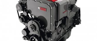
As already mentioned, without a fuel pump, the operation of a diesel power plant is not possible. In engines of this type, the unit is entrusted with the task of dosing diesel fuel and supplying it to the combustion chamber at the right time. In addition, the pressure with which the portion is delivered is also important. The requirements complicate the work algorithm and force us to operate under increased load conditions.
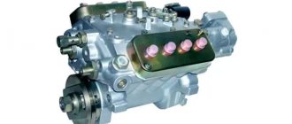
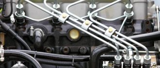
Fuel injection pump YAZDA 337.20 for KamAZ:
KamAZ power plants, with an environmental class corresponding to Euro 2, use high-pressure pumps of several brands. Among manufacturers, the “lion’s” share falls on fuel injection pumps of the YAZDA series, used on KamAZ Euro 2. Products of the modification “337.20” are produced by a machine-building enterprise located in the city of Yaroslavl. The product is popular and accessible primarily due to its pricing policy. In addition, reliability and simplicity make the pumps less demanding, and balances the disadvantage associated with the accuracy of fuel dosage. Second place goes to the imported Bosch injection pump, installed on KamAZ of Euro 2 standard. The product is distinguished by its quality and accuracy, but there are often complaints about the pump drive, which does not withstand operating conditions.
The operating principle of the pump is the same, the brand does not matter. Diesel from the fuel container passes through filter elements that clean the liquid. The pistons of the low pressure pump create pressure and supply diesel fuel to the injection pump. The parts regulate the necessary operating order, distributing diesel fuel through the pipes and directing it to the sprayers. The latter are responsible for dispersion, which affects the correct combustion. Some of the unused diesel fuel goes back into the fuel tank, while some remains in the pipes. You can also read about KamAZ 7850.
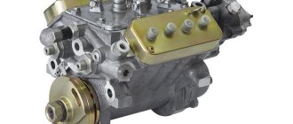
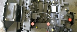
Bosch injection pump for KamAZ:
Features of injection timing adjustment
What is the injection moment on KamAZ
The design of the ignition system of diesel trucks is somewhat different from their gasoline counterparts, where the task of igniting the mixture of gasoline and air is assigned to spark plugs. For a diesel engine, the term “injection timing” is more appropriate. In order for the power unit to start working, it is necessary to create high pressure in the chamber. After this, the fuel supply is turned on. The system begins to work when the piston approaches the top “dead” point.
If the system parameters are set incorrectly, engine parts may malfunction or overheat. It all depends on how the fuel mixture ignites - late or advanced.
Risks of untimely injection
- the engine becomes rough;
- when the accelerator is activated, a ringing sound occurs;
- the exhaust looks like white smoke;
- fuel consumption increases.
Late ignition is characterized by the flow of fuel when the piston leaves the upper position. In this case, the main signs of a malfunction are:
- a significant amount of whitish smoke from the exhaust pipe;
- decreased cravings;
- engine heating;
- increased fuel consumption;
- incorrect speed dial;
- vibration of the unit at medium speeds.
If any of the symptoms are observed, the KamAZ ignition must be adjusted as quickly as possible.
Adjustment procedure
On each engine you can notice special marks or degrees. They are intended to guide the driver who is solving the problem of how to set the ignition on a KamAZ.
In order for the engine to operate in normal mode, it is necessary that the characteristics of both the injection pump, the fuel, and the unit itself meet the requirements of the regulations. It is the marks that help determine how to set the ignition on a KamAZ correctly.
On the machines of the Kama plant, the pump that supplies fuel under high pressure is installed using a key on the side of the box. The pump coupling can be secured in two positions, the difference being 180 degrees. When the screw holding the drive is at the top, the marks of the injection pump and the pump coupling should be found opposite.
So, to check the ignition system, you need to:
- install the elements according to the marks;
- fix all elements;
- start the engine.
If the above malfunctions are observed, it means that the components are placed incorrectly and the operation should be repeated: loosen the elements, check the installation at 180 degrees, secure the components and start the engine.
The coordinated operation of the engine is important for the functioning of the vehicle as a whole: the KamAZ gearbox shafts will not be able to perform their task if problems are observed in the operation of the unit itself.
In conclusion
Despite the fact that the diesel power unit has a simple and understandable design, the elements of its fuel system are considered high-precision devices. In this regard, the installation of a high-pressure fuel pump requires special attention and optimal determination of the angle of injection of diesel fuel through the nozzle into the working cylinder at the compression stage. Even an error of just one degree can lead to engine failure, which will require an emergency overhaul. Reliable KamAZ Euro trucks are popular in various areas. How to set the ignition on different modifications is discussed above. Knowing the features of this procedure, it is quite possible to adjust the timing of fuel injection on your own with minimal investment of time and equipment.
How to determine fuel injection pump malfunctions
Please note that it is best to test the high pressure pump on professional stands specifically designed for this purpose. They allow you to find out the operating characteristics of the pump and other elements of the vehicle’s fuel system.
However, such a check is only possible in a car service center, since such a stand is specialized and expensive equipment. In garage conditions, it is possible to carry out only a partial check of the fuel injection pump and determine only the main fault, while other possible faults will not be noticed!
Checking the presence of water in plunger pairs
To do this, you need to remove the timing belt and carefully twist the pulley. If it rotates with variable force, then everything is fine and there is no water in the pump
Important Characteristics of the popular Soviet mining dump truck KrAZ-256B
If rotation occurs under the influence of significant force and does not occur at all, then moisture is present. This is very harmful for both the pump and the engine as a whole, since the motor will work with increased effort when starting, until it completely jams (failure).
Checking the pressure in the plunger pair
There are special tools for this - testers, for example, KI-4802 or TAD-01A. If you don’t have such a tool at hand, you can use a pressure gauge with a high measurement range. So, it needs to be screwed into the seat of the fuel pipe, or into the central hole of the high pressure pump head. With a normal running engine, pressure readings should be approximately 300 kg/cm² and above (in fact, the corresponding value will vary for different brands of cars, as well as engine operating modes). If the fuel pressure is lower, it means that the plunger pair has worn out significantly and needs to be repaired or replaced (most often).
Control sensors
Modern common rail diesel systems that are controlled by an ECU (electronic control unit) tend to have problems with the sensors and/or their signal wiring. This often activates the Check Engine light on the dashboard. You need to use an error scanner to read their numbers and decipher them. Next, in accordance with the information received, make a decision on repairs.
Gas distribution mechanism of the KamAZ-740 engine
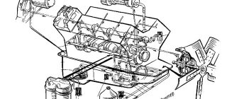
The gas distribution mechanism of this engine consists of a camshaft 1 (Fig. 14) with a gear 17, pushers 2 with guides 3, rods 4, rocker arms 6 with adjusting screws 5 and locknuts 7, intake 14 and exhaust 15 valves with springs 10, 11 and parts their fastening, camshaft drive.
Fig. 14. Gas distribution mechanism
Pushrods transmit force from the camshaft cams to the rods. The cylindrical guide part of the pusher is hollow, it has two holes for draining oil from the internal cavity. This oil lubricates the side surface of the pushers and the camshaft cams. The inner surface of the pusher ends in a spherical socket where the lower end of the rod rests. The end surface of the pusher, coupled with the cam, is overlaid with bleached cast iron to increase wear resistance and has a disc-shaped shape.
The pushers are installed in cast iron guides attached to the cylinder block. When the engine is running, the pushers constantly rotate around their axes, which ensures their uniform wear. The rotation of the tappets is achieved due to the spherical surface of their plates and the beveled surfaces of the camshaft cams. The rods transmit force from the pushers to the rocker arms; they are made of steel, hollow, with insert tips. The lower tip has a convex spherical surface, the upper tip is made in the form of a spherical cup. To allow lubricant to pass through the rods, there are holes in the tips.
The rocker arms transmit forces from the rods to the valves and are made of steel. Each rocker arm is a two-arm lever, into the hole of which a bronze bushing is pressed. The nose of the long arm of the rocker is hardened to high hardness. An adjusting screw with a lock nut is screwed into the short arm of the rocker to adjust the gap between the rocker and the end of the valve stem.
The rocker arms of the intake and exhaust valves are installed on a common stand, secured to the cylinder head with two studs. The axial movement of the rocker arms is limited by a plate clamp installed under the rack. The rack has a hole for supplying oil to the rocker arms.
Valves are designed to open and close intake and exhaust valves. Each cylinder has one intake and one exhaust valve. Both valves are made of heat-resistant steel. The valve consists of a head and a stem; the head has a working chamfer, and the rod has an annular groove. The diameter of the intake valve head is larger than that of the exhaust valve, this improves the filling of the cylinder with air. The working chamfer of the exhaust valve head, operating at high temperatures, is reinforced with a wear-resistant and corrosion-resistant alloy called stelite.
What is the injection pump used for?
The main difference between a gasoline unit is the ignition of the combustible mixture inside the cylinders. In a gasoline engine, the mixture is ignited by spark plugs. In a diesel engine, the mixture spontaneously ignites under compression. The injection pump is needed for the timely supply of diesel fuel to the cylinders at the moment of compression.
By design, injection pump pumps differ as follows: in-line type, main type and distribution type. In an in-line engine, diesel fuel is pumped into each cylinder from its own pair of plungers. The distributor provides all cylinders with one or two pairs of plungers. Mainline devices are used to pump diesel fuel into the fuel accumulator.
Remember, injection pump and injectors are the main elements of the diesel ignition system. They are present in most diesel units and are of the electronic type.
Reasons for adjusting the ignition on KamAZ
The stage of supplying a flammable substance, which is carried out by the piston, is ignition. As the piston approaches top dead center, an increase in pressure occurs, this is due to air compression. It is at this moment that fuel needs to be injected. If the injection advance angle is incorrect, problems arise with the KamAZ ignition.
There are early and late injections.
Early injection is characterized by advanced ignition of the fuel, which occurs before the piston reaches top dead center. As a result, there is an increase in energy consumption to lift the valve.
Late injection - characterized by delayed ignition of the fuel, which occurs at the moment the exhaust valve closes. As a result, there is no impulse to the piston, and overheating of the engine system occurs.
The presence of an early injection moment is indicated by:
- Rough engine operation
- The car doesn't pull well
- The amount of fuel used increases
- Sometimes white smoke appears (affected by feeding too early)
- The presence of a ringing sound reminiscent of valves during a sudden change of gas or when the load on the engine increases.
The presence of a late injection timing is indicated by:
- The presence of white smoke, the amount of smoke increases with increasing lag. Often appears on the engine at low temperatures
- Increasing the number of revolutions
- The motor runs smoothly
- When you press the pedal smoothly, the engine shakes at medium speeds, after which it stops shaking at high speeds.
- The car does not pull with enough force
- Fuel consumption increases
- The engine temperature increases.
These signs can help identify ignition errors, which will help determine the direction of rotation of the drive during adjustment.
The result of ignition with early and late injections is incomplete combustion of fuel, malfunction of the cylinders, and subsequently rapid wear of parts and the engine as a whole.
When and why adjustment is needed
While the system is operating, the piston approaches top dead center, high pressure is generated in the chamber and fuel is supplied. If the injection timing is set incorrectly, the fuel mixture ignites late (late injection) or ahead (early injection). This leads to incomplete combustion of fuel and malfunctions in the operation of the cylinders, respectively, to a decrease in engine efficiency and increased wear of parts.
When the mixture burns ahead, the piston does not yet reach the top point, at which time the fuel enters the chamber. There is an excessive waste of energy in lifting it; the released gases and the burning mixture resist. With late ignition, combustion ends with the expansion stroke and the exhaust valve closing. As a result, the piston does not receive impulse, the energy is distributed between the pusher and the block walls, which leads to overheating.
Signs of early and late inflammation:
- inability to start the engine;
- high fuel consumption;
- decreased throttle response and power;
- uneven engine operation at idle speed;
- malfunction of the fuel mixture quantity regulator.
Therefore, it is necessary to adjust the ignition system (I).
Types of ignition systems
The timing of injection affects the quality of KamAZ trucks. Early starting entails the impossibility of the piston to take the upper position until the fuel enters the chamber cavity.
The following signs may indicate this:
- Hard work of the power plant.
- Pressing the gas causes an unpleasant ringing sound. The sound increases when the temperature of the power plant increases.
- Low force pull.
- Increased fuel consumption.
Late ignition has other consequences. The fuel moves at the same time as the piston begins to go down. The appearance of the spark occurs later and this event completes the process.
The following signs may indicate this situation:
- White smoke coming from the exhaust pipe. At the same time, the amount of smoke is directly proportional to the complexity of the problem.
- Incorrect number of revolutions made by the motor apparatus.
- The power plant is too soft.
- The motor shakes even if the pedal is pressed smoothly.
- The amount of fuel used increases.
- The engine increases the temperature to a critical level.
- Weak vehicle traction.
Basic rules for installing injection
- It is preferable to start manipulations at the operating temperature of the motor. However, if the symptoms are obvious, then you can start working in cold weather.
- We install the drive so that the mark is on top, then lower the two bolts by 17 degrees.
- If the injection is early, then move the pump drive in the direction of travel or clockwise.
- If the injection is late, then vice versa.
- You need to move the drive a little at a time and constantly tighten the bolts.
After all the manipulations, we start the KamAZ engine, such as art. 337 1111005 20
It is important that when it is activated during a sharp throttle, a ringing sound is heard. In this case, move the drive back a little
The ringing will disappear, and the moment will be established.
Ignition installation KamAZ Euro-3 fuel injection pump Bosch
The main difference between KamAZ Euro-3 and KamAZ Euro-2 is the presence of an ignition switch. The ignition switch activates the on-board network to the battery and generator and turns off after the engine starts. Has three positions:
- initial (no current in the system, mechanisms do not work)
- position 1 (engine is switched off, but individual components are working)
- final (starting the engine).
The first position indicates the inoperative state of the vehicle's devices is disabled; when switching to position 1, it becomes possible to turn on some mechanisms (audio system, optics) that are included in the ignition system when the drive engine is turned off. The final position is responsible for starting the engine.
The ignition switch can perform an anti-theft function; when the engine is off, it locks the steering wheel.
- Turning the drive clockwise enhances early injection;
- Turning the drive counterclockwise normalizes late injection.
Important TOP 8 Countryman cultivators with electric and gasoline engines
The concept of KamAZ ignition
Passenger cars with a gasoline engine begin their movement due to the appearance of an electric spark in the candles. Most heavy vehicles have diesel engines. For cars with a diesel engine, the ignition system is carried out by creating pressure (compression) and heating a flammable substance. For trucks, motorists call the “injection moment” the familiar concept of “ignition”, which came from the owners of cars with a gasoline engine, in which a spark ignites in the spark plug at the moment the engine starts.
Settings
Injection timing and ignition are different names for the same process. Injection is the start of the supply of fuel mass when the piston moves to the maximum point. The KAMAZ EURO 2 starter must be in good working order. The intake valves must be closed, as well as the check valves. Due to this, maximum pressure appears in the functioning chamber. At the same time, fuel is supplied.
Of course, diesel cars are tuned during factory maintenance. However, such debugging is not enough. Due to operating conditions and varying quality of automotive fluids, the adjustment must be repeated periodically.
Each power plant has special marks (or degrees), which are marked for the convenience of self-calibration. If the device is debugged and the settings are set according to the marks, the motor will function in its optimal mode. The KAMAZ EURO 2 engine, fuel, lubricants and spare parts used in the process must comply with all GOST requirements.
After the procedure, during which the car owner has set all elements of the system to the factory marks, he must firmly tighten the special clamps on the engine and turn it on. The vehicle should not have any problems starting and should start the first time. If this does not happen, or white smoke begins to come out of the exhaust part, then this indicates an error - the injection pump has been positioned 180 degrees. The error is corrected in the reverse way: the parts are unscrewed, the elements are rotated, and the engine is restarted.
If there are no factory marks, the elements must be installed in the middle position of the adjustment marks
To ensure correct installation, special attention must be paid to the injection time.
Installing the mark on the fuel pump
That is, if you rotate the engine as you go. And the mark aligns with the peak of the index arrow. At this moment, fuel is injected into the combustion chamber.
Then the mark continues to move, and at the moment of alignment with the edge of the index arrow. The piston reaches the TDC position at the moment of compression of the fuel in the first cylinder.
And now I would like to tell you in more detail how to do this in practice without error. The position of the piston at TDC is fixed using a stopper located on the flywheel housing.
But since during one revolution of the injection pump shaft the piston passes twice to the TDC position. And we need to determine the position of TDC at the moment of fuel compression in the first cylinder. If you do not remove the high-pressure fuel pump, then simply move the mark on the injection pump coupling to the index arrow. Release the stopper somewhere in this place, and by rotating the flywheel in one direction or another, ensure that the stopper falls into the groove of the flywheel. It is most convenient to turn the flywheel using a lever. Which must be inserted into the holes located at the end of the flywheel.
In this position, the piston will have the TDC position at the moment of compression of the fuel of the first cylinder. Having loosened the bolts of the injection pump drive coupling, align the mark with the edge of the index arrow. In practice, this position of the mark has been verified to be the optimal ignition timing angle. Shifting the mark in one direction or another leads to improper operation of the engine, it begins to smoke and develops poor speed.
It is much more difficult to determine the position of the TDC of the piston at the moment of compression. If the injection pump has been removed from the engine and needs to be reinstalled. The difficulty lies in determining the TDC position of the piston of the first cylinder at the moment of compression. Since the crankshaft drives one revolution of the drive shaft. The fuel injection pump makes two revolutions; therefore, the piston comes to TDC twice, and we need the moment at which the fuel is compressed. You can, of course, remove the nozzle and plug the hole with a paper plug.
The compression created in the cylinder during compression will push the plug out. At this moment, the stopper will fall into the groove of the flywheel, which will be the position of the piston of the first cylinder at the moment of fuel compression. But this method is not good enough, as it is time-consuming and labor-intensive.
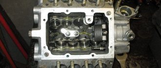
Euro 2 ignition adjustment on a Kamaz vehicle can be determined by the position of the valves. At the moment of compression, the valves become motionless until the piston reaches TDC, and after passing TDC, the valves are also closed. At the second position of the piston at TDC, one valve closes, and when passing TDC, the second valve begins to open. And to verify this, simply open the valve cover of the first cylinder.
Source
Ignition system
There are a number of requirements for the launch system itself that are necessary for the normal operation of the car. These include:
- creating a spark in the cylinder at a certain moment;
- ensuring a rational engine starting moment, that is, the spark should appear with optimal advance, the interval of which varies depending on the engine speed and the current load;
- a certain strength and energy of the spark, the quantitative value of the energy varies proportionally depending on the physical and chemical characteristics of the fuel mass.
Ignition can be carried out in the following ways:
- through the microprocessor of an electronic device, where electrical energy is stored. The microprocessor controls the resulting energy and creates a spark;
- contact method, where the process is controlled by a special distributor - distributor;
- in a contactless way, where what is happening is controlled by a transistor switch that interacts with contactless sensors.
The processes are different, but the design itself has many similar parts. For example, spark plugs, a battery, a switch, devices for distributing and accumulating charges, as well as a 1703 KAMAZ belt.
Read more: Mercedes-AMG A45 2022 photo price and characteristics of a powerful hatchback from Mercedes 2nd generation
Is the injection angle adjusted correctly?
It is necessary to check the correct ignition settings by turning the engine on and off. If there are signs of incorrect engine operation, you must repeat the described steps until the desired result is obtained. Correct installation is indicated by the absence of extraneous noise and the speed at which the motor starts. You can verify correct operation by using the idle speed. The rotation speed should be 600 rpm. Do not forget about safety precautions while working. Make sure the fuel supply system is turned off and you have secured the vehicle.
What could be better for you and your car?! And the increase in your truck's fuel consumption will be felt quickly, the moment you make a quick visit to the gas station and pay the check. Keep an eye on the health of your iron “friend”!
source
We adjust the injection experimentally
Injection adjustment is made experimentally after installing the pulley. After installing the pulley, start the engine. If it does not start, then rotate the injection pump pulley relative to the timing belt by 2-4 teeth.
Start the engine again.
After the manipulations we have performed, it should start, listen to the operation of the motor. Obvious knocking sounds mean detonation; you need to turn the pump pulley in the direction 1-2 teeth opposite to its rotation. Thick gray smoke means late injection, then the pump pulley must be turned 1 tooth in the direction of its rotation.
If there are no changes for the better in the operation of the diesel engine, you need to rotate the pump around the axis. With such rotations it is necessary to achieve optimal operation of the unit. The best setting option would be to work in the mode before detonation knocks appear. They are very audible when the diesel engine is running.
The second method of the experimental method involves the following steps:
We unscrew the tube that goes from the pump to the injector on the first cylinder. Pull a transparent hose onto the removed end of the tube and place it in a vertical position.
Now you need to turn on the ignition and slightly turn the injection pump pulley. Rotate the pulley little by little, slowly and very carefully. At the same time, monitor the fuel level in the transparent hose. Determine the highest limit. When the diesel level is at the upper limit, make a mark on the pump pulley.
After this, the camshaft and crankshafts are set according to the marks. Start the engine and check its operation. If there are signs of improper injection, repeat the adjustment procedure again. If it still doesn’t work out, contact the service station, they will fix everything and, if necessary, adjust it at the stand.
That's all, friends, until we meet again, subscribe to the site update, if you haven't yet, share the link with your friends, if you haven't done so yet, there will be a lot more useful stuff.
Pump departments
The pump section dispenses and supplies diesel fuel to the nozzles. Each unit includes a frame, a plunger pair, a rotation sleeve, elastic elements of the plunger, a discharge valve and a pusher.
Important How to choose a suitable walk-behind tractor for plowing a plot of land: tips, video
The frame is equipped with a flange that secures the section to the pump using studs. The pin holes are oval in shape; it is possible to adjust the uniformity of diesel supply to each compartment individually (turning clockwise reduces the supply, and vice versa). The plunger pair is directly involved in cutting off and transporting diesel fuel and consists of a sleeve and a plunger. The parts are precision made, the material is steel with the addition of chromium and molybdenum, followed by hardening and cooling with nitrogen. The plunger acts as a piston, has axial drilling and radial grooves that change the flow of diesel fuel. The precision pair of discharge valve and seat are made of steel, after the elements are hardened and cooled. Replacement of components is possible only as an assembly.
KamAZ injection pump cam shaft:
Shaft with cams
The shaft with cams transmits displacement to the plungers of the pump sections, diesel fuel is supplied to the chambers at the right time. The shaft is made of steel, the loaded surfaces are calcined with cement powder to 0.7-1.2 mm, rotation occurs through two bearings. The shaft is protected from leaks by a cuff, the material of the product is rubber. The front end of the shaft drives a clutch that sets the diesel injection angle. Rotating, the shaft transmits pressure to the pushers and then to the pump plungers through the heels. By changing the thickness of the heels, we influence the nature of the fuel supply; an increase in thickness provokes an early supply and vice versa.
Install the ignition on KamAZ
We will answer the question posed using the KamAZ 740 as an example. To do this, we will describe the ignition procedure of the KamAZ 740, which is similar to many models of this class.
Installation of the KamAZ 740 ignition is carried out in several stages:
- getting started we'll start by raising the truck cab
- we will fix the cabin on supports to protect the person’s work
- find the flywheel on which you will find the rod, it is located on the back of the flywheel on the top left side.
- lift the rod and rotate it ninety degrees, then return it to its original place
- find two bolts on the flywheel housing, unscrew them, you will need a seventeen mm wrench.
- To continue working, remove the mudguard
- through the slotted passage of the casing into the flywheel we insert a hard alloy rod 400 mm long and 10 mm in diameter
- perform rotational movements with the crankshaft until movement is blocked
- if the injection pump coupling is located with the scale up, you need to ensure that two marks coincide: zero with the mark on the fuel pump flange, secure with two bolts
- if the part is positioned in the opposite direction, lift the stopper and rotate the crankshaft one 360 degrees. After this, repeat the steps described above.
DEVICE OF injection pump KAMAZ EURO 2
Injection pump device KAMAZ Euro 2 1. Low pressure fuel pump 2. Regulator top cover Regulator top cover 3 . Regulator weight holder 4. Regulator coupling 5. Rear regulator cover 6 . Levers with correctors 7. Starting spring lever 8. Drive regulator gear 9. Regulator intermediate gear 10. Boost corrector 12. Fuel pump housing 13. Fuel pump section 14. Cam shaft 15. Camshaft bearing cover 16. Plunger pusher 17. Bypass valve 18. Right rack 19. Left rack 20. Rack lever assembly 23. Pusher 24. Pusher roller 25. Pusher roller axis 27. Pusher spring 28. Fuel pump gasket 29 . Fuel pump drive eccentric 30. Regulator top cover gasket 31 . Regulator lever axis 32. Remote bushing 34. Regulator rear cover gasket 35 . Rack lever spring 36. Regulator spring 37. Spring lever 38. Drive gear block 39. Drive gear flange 40. Regulator rear cover plug 41 . Spring thrust ring 42. Pin tip 43 . Corrector gasket 49. Flange of the driven coupling half 50. Driven coupling half 51. Rear bearing cover 52. Gasket 53. Gasket 53. Gasket 54. Gasket 54. Gasket 55. Gasket 55. Gasket 56. Protective casing 58. Plug 60 . Pusher heel 69. Key 6x9 70 . Screw M8x20 71 . Screw M6x43 72. Screw М8х6g-19 73 . Screw M6x43 74 . Nut M20x1.5-6N 75. Washer 17 76. Flat washer 10x18 80. Bolt M6-6gx20 81. Screw M6-6gx32 83. Washer 16 84. Washer 17 85. Washer 7 86. Washer 21 88. Key 89. Lock washer 15 90 . Cork M10x1.25-6g 92. Plug of fitting 98. Spring washer 10 99 . Spring washer 102. Adjustable cotter pin 2x25 103. Low nut M14x1.5-6N 104. Bolt M6-6gx25 105. Lock washer 5x11x0.7 106. Conical spring washer 6x12 107. Nut M10x1.25-6N 108. Nut EM6-6N 110. Nut M8-6N
Injection pump repair
Troubleshooting methods for a high-pressure fuel pump depend on the type of device, as well as the cause of the breakdown. We list the most common repair measures.
Replacing the plunger pair with your own hands
Before performing an independent check (without using a special stand), you must have handyman tools and a new plunger pair on hand, as well as have experience in performing repair work. We will describe the description of checking the condition of the high-pressure fuel pump using the example of a common Bosch injection pump.
It is necessary to understand that dismantling the pump depends on the specific model and even the car engine, so the procedure will be described in general terms. So, to replace a plunger pair (the most common type of repair) you need to:
remove the terminals from the car battery; disconnect all wires and hoses suitable for it from the high-pressure pump; dismantle parts that prevent its removal from the car; unscrew the fasteners and dismantle the pump; carefully disassemble the pump, it is important not to lose small parts, and also remember the disassembly sequence (you can photograph this process step by step on your phone); unscrew and remove the plunger from the pump; clean all pump parts from dirt (you can use special carb cleaners or similar cleaners for this); check the rollers, bearings and racks on the pump; they should not show significant wear; remove the valves and the so-called “silencer” from the old plunger pair, and then install them on the new pair; Carry out installation work in reverse order.
Please note that replacing the plunger pair can only be done if you are completely sure that this unit is partially out of order, since it costs a lot of money
Rack jamming
If you find that the rack is sticking, then the first thing to do is to find the place where it is “sticking”. This can be done by pumping up the ring gear relative to the rack in the corresponding section. If the rack does not jam, then there will be a small gap.
In this case, independent repair is hardly possible. However, in any case, it is necessary to dismantle the pump and show it to a specialist!
Preventive measures
As you know, prevention is the best repair, therefore, to save money and ensure normal engine operation, it is advisable to carry out simple preventive measures that will help extend the life of the high-pressure fuel pump. In particular:
flushing the fuel system should be performed approximately once or twice a year; be sure to change the fuel filter on time (it is not advisable to clean it, because small particles of dirt will most likely remain on the filter); use high-quality fuel (at any gas station there is documentation indicating how long ago the fuel was delivered, as well as information about its composition, tolerances and seasonality); in winter, it is important to use winter diesel fuel, or to lower the freezing point (increase fluidity) of diesel fuel, you can use special compounds - antigels; it is advisable to leave the car for long periods of time (especially in cold weather) with a full tank, since moisture condensation forms on the inner walls of the tank overnight, which flows down and mixes with the fuel; instead, you can use the moisture removers mentioned above; do not allow the fuel level in the tank to drop critically; in winter, it is imperative to warm up the engine for several minutes before driving, taking into account the coolant temperature and oil pressure gauge readings; use special lubricating additives for diesel fuel if there is a suspicion of low quality diesel fuel.
The measures listed above will contribute to the normal operation of not only the high-pressure pump, but also the entire fuel system of the car as a whole.
Gas distribution mechanism KAMAZ 740.10
The engine is equipped with an overhead valve timing mechanism with a lower camshaft.
KamAZ gear block
· KamAZ valve rocker arms
· KamAZ valve springs
KamAZ camshaft
· Pushers, KamAZ pusher rod
The gear block , located at the rear end of the engine block, drives the timing shaft, high-pressure fuel pump, compressor and power steering pump of the vehicle. The gas distribution mechanism is driven into rotation by an intermediate gear 2 connected to a spur gear 1 mounted with interference on the crankshaft. The idler gear unit rotates on a double tapered roller bearing. Driven gear 4 of the gas distribution mechanism drive is mounted on the shaft journal with tension and is in mesh with gear 5 of the fuel pump drive. The gears are assembled in such a way that the marks of the gears in mesh (shown in circles) are aligned. The drive shaft of the high-pressure fuel pump is a cardan shaft, with elastic diaphragm-type elements that compensate for the misalignment of the installation of the fuel pump shaft and the gear shaft.
Figure 8. KamAZ timing gear block: 1 - drive gear; 2 and 3 - intermediate gears; 4 - camshaft gear; 5 — fuel pump drive gear; 6 — power steering pump drive gear; 7 — compressor drive gear.
Gear 5 is meshed with gears 7 and 6 mounted on the shafts of the compressor and power steering pump drives.
The valves are made of heat-resistant steel. Each cylinder has one intake 9 and one exhaust 6 valves. The design of the intake and exhaust valves is the same. The valve stem is graphitized before installation. The operating chamfer angle of the valves is 91°. The diameter of the intake valve plate is 51.5 mm, the exhaust valve is 46.5 mm; valve lift height 13.5 mm. The valves move in guide bushings 4 made of metal ceramics. To prevent oil from entering the cylinder along the rod-bushing gap, a cuff 12 is installed on the intake valve bushing.
The valve drive consists of pushers, rods, and rocker arms. The valves rotate when the engine is running.