EURO-2 KamAZ- 6360-06, 6460-06, 5360-06, 5460-06
Technical characteristics of fuel injection pump 337-40, 337-70 engine
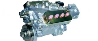
The injection pump 337-40 KAMAZ 740 is a high-pressure fuel pump, which is equipped with sections with a V-shaped arrangement and has a distance between sections of 36 mm. The fuel injection pump 337-40 is equipped with a regulator with two modes, as well as a direct and reverse corrector. Produced since 1995.
Number of fuel injection pump sections
Diameter/maximum stroke of plunger (mm)
N nom. (hp) at n (min -1)
Where is the injection pump 337-40 used?
EURO-1 KamAZ-55111-02, 65115, 53212-02, 54112-02, 54115, 53215, 53205-02, 53213, 53202, 53229-02, 54105-02, 53228-02, 4326, 4350 .
Rules 96 Combine “Don-1500”
Rules 96 Tractors T-150K, HTZ-170, IFA feed chopper
Buses: NefAZ-5297, PAZ-5272, LiAZ-5256
Technical characteristics of fuel injection pump 337-42 engine
The injection pump 337-42 is a high-pressure fuel pump, which is equipped with sections with a V-shaped arrangement and has a distance between sections of 36 mm. The injection pump 337-42 is equipped with a mechanical all-mode regulator, as well as a direct and reverse corrector. Produced since 2002.
Number of fuel injection pump sections
Diameter/max. plunger stroke (mm)
N nom. (hp) at n (min -1)
Where is fuel injection pump 337-42 used?
EURO-1 KamAZ-43118, 44108, 65111, 6540
Rules 96 Combine “Don-1500”
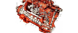
The KamAZ injection pump is a mechanism designed to supply fuel fluid to the cylindrical mechanisms of the engine.
Design and principle of operation
The fuel injection pump device includes such mechanisms as:
- pump compartment housing;
- high pressure fuel pump bearing cover housing;
- inflation hose;
- plunger pair and plunger pusher;
- spring elements;
- mode selection regulator and coarse and fine filters;
- fitting for the fuel drain and injection system;
- fuel injection regulator;
- pressure reducing valve;
- an electromagnetic valve, which is necessary to shut off the fuel supply;
- rack, nozzle and coupling half.
The operating principle of the injection pump is as follows:
- Movement is set from the crankshaft mechanism using a mechanical transmission.
- The rotation of the cam shaft begins. This rotation provokes displacement of the pusher elements.
- The pushers begin to compress special springs.
- The springs cause the plunger to start working and lift it.
- The plunger closes the intake valve and displaces fuel fluid.
- The fuel begins to be sprayed using nozzles.
- The plunger lowers and opens the intake mechanism.
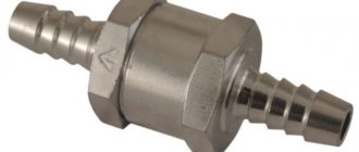
Where is the check valve located?
The check valve is located on the fuel rail between the fuel tank and the injectors.
Replacing and adjusting plunger pairs with your own hands
The high pressure fuel pump is the most important component in every diesel engine. Because of this mechanism, the fuel becomes not just a liquid, but a fuel-air mixture. The operation of the pump is also influenced by such a part as a plunger pair. She is responsible for the supply of fuel and its distribution.
Malfunctions and repairs
You can repair KamAZ fuel injection pump yourself if you have the necessary tools and equipment.
Main fuel injection pump malfunctions and reasons for their occurrence:
- Water in the fuel mechanism. This breakdown may indicate a malfunction of the fuel filter element, diluted fuel, or a leak in the fuel drives.
- Reduced and uneven supply of working fluid. In this case, it is recommended to check the plunger for damage, and also inspect the discharge valves and rack clamps. The capacity of the injectors should be checked.
- The diesel fuel is running out. The cause of this breakdown may be a leak in the fuel drive. The damaged element should be replaced.
- The drive is tearing. It is recommended to inspect the crankshaft, as well as the main components of the power unit for damage and foreign bodies.
- Delay of the working fluid injection system. Such a malfunction can be caused by damage to the plane of the adjusting bolt of the pusher element, the roller axis and failures in the rotation speed of the cam shaft.
How to remove and disassemble
Removal from engine:
- Remove the terminal from the battery.
- Remove the radiator.
- Remove the vacuum pump.
- Remove the oil dipstick guide pipe.
- Remove the oil filter filter mechanism.
- Turn the crankshaft in the direction of rotation until it stops.
- Disconnect fuel drives.
- Remove the vacuum hose.
- Block the crankshaft from turning.
- Unscrew the bolt in the center of the coupling.
- Remove the chain tensioner.
- Pull out the pump by dismantling the fuel pedal drive.
Disassembling the KamAZ fuel injection pump is done as follows:
- It is necessary to remove the metering type valve from the end of the pump housing. To do this, you need to unscrew the bolts of the pressure plate and release the advance valves of the injection system.
- Then you should remove the fastenings on the top cover.
- You need to disassemble the control board to gain access to the electronics.
- It is necessary to set the required position of the crankshaft.
- Then you need to dismantle the bearing using special equipment.
- At the end, all parts should be washed and their surface polished.
How to add or reduce fuel
Adjusting the Bosch injection pump on KamAZ makes it possible to add fuel, i.e. set the required fuel supply value.
Procedure for reducing fuel:
- Using a key of 13, you need to adjust the air flow to the mechanisms of the power unit. Thanks to this, diesel will be able to mix with air.
- Make adjustments to the corrector and start the motor for testing.
- If necessary, you need to further tighten the air flow until the smoke stops coming out.
In order to add fuel to the KamAZ injection pump (Euro-2 or Euro-3), you need to do the following:
- Tighten the special screws that are located in the upper and side parts of the working fluid supply.
- When unscrewing the bolts, you need to increase the gap for the passage of the combustible mixture. This will help normalize the performance of the power unit and the lubrication system of the high-pressure fuel pump.
- Having increased the diameter of the hole, you should start the engine and check the operation of all systems.
Video of adjusting the Kamaz fuel pump
Installing fuel injection pump and adjusting KamAZ ignition
How to add or decrease fuel on a Kamaz injection pump
Kamaz 55111 I set the ignition and a little about the clutch
Repair of fuel injection pump KAMAZ
After adjusting the Kamaz injection pump
How to add traction on a Kamaz.
Super ignition unit (OVT) for KamAZ and MTZ, which has no analogues in the world.
Checking the pressure of plunger pairs. KAMAZ (YAZDA).
How to make KAMAZ economical
Start regulator 003.AVI
TECHNOLOGICAL CARD No. 2. 5.
TESTING AND ADJUSTING THE HIGH PRESSURE FUEL PUMP (HIGH PRESSURE FUEL PUMP) OF THE KAMAZ-740 ENGINE
Total labor intensity - 235.0 people. min.
Performer - mechanic for repairing fuel equipment of the 5th category
EQUIPMENT, DEVICES, TOOLS
Test bench for fuel pumps Minor-8B, NTs-128 or STAR-12F; stopwatch SM-60 GOST 5072-72; caliper ShTs-1-125-0.1 GOST 166-80; dynamometer 06-8790-4017; air dispenser S-413; device for removing and installing automatic injection advance clutch I 801.16.000; a special wrench for unscrewing the automatic clutch fastening nut; open-end wrenches 10.17 mm GOST 2839-80; combined pliers GOST 17438-72; measuring container for filling oil; measuring container for fuel PREPARATORY WORK Labor intensity - 11.0 people. min.
1. Install the injection pump on the stand. The injection pump can also be adjusted on stands: MTs-104 (Czechoslovak) MD-12 (Hungarian); A1027 (Austrian), etc. (Stand STAR-12).
2. Fill the pump with oil. Oil M10G2K GOST 8581-78 in a volume of 0.16 l to the level of the drain hole on the rear cover of the regulator. (Measured container).
3. Install a plug instead of the bypass valve 27-32 (Fig. 1). (Spanner 17 mm).
4. Connect the fuel supply line to screw 21 of the pump housing. (Spanner 17 mm).
5. Connect the drain pipes to fittings 48 of the injection pump.
6. Set the rack to the position corresponding to the fuel supply being turned off.
7. Remove the automatic fuel injection advance clutch.
CHECKING AND ADJUSTING THE START OF FUEL SUPPLY OF THE KAMAZ-740 ENGINE
Labor intensity - 8.0 people. min.
8. Check the order of alternating the start of fuel supply according to the angle of rotation of the cam shaft. The start of fuel supply by the pump sections is determined by the angle of rotation of the pump camshaft when rotating it clockwise, as viewed from the drive side. The first section of a correctly adjusted pump begins to supply fuel 42°30′ ±30′ before the axis of symmetry of the cam profile. At the moment the eighth section of the pump begins to supply fuel, the marks on the pump body and the driven coupling half must coincide. Mark discrepancy ±0.5 mm.
If the angle at which the eighth section begins to supply fuel is conventionally taken as 0°, then
The discrepancy between the start of fuel supply by any pump section relative to the first is allowed no more than 20′. The adjustment is made by installing a certain thickness of the pusher heel 64 under the plunger 61. A change in its thickness by 0.05 mm corresponds to a 12′ angle of rotation of the cam shaft. When installing a thicker heel, fuel begins to be supplied earlier, and a thinner one - later. Check the tightness of the discharge valves.
Price and reviews
Injection pump purchase and rental price:
- purchase - from 17,500 rubles;
- This vehicle part cannot be rented.
Vladimir, 39 years old, Magnitogorsk: “I’ve been working at KamAZ-53215 for the second year now. Recently I started having problems with the high pressure fuel pump. A Euro-3 version was installed, and the fuel injection pump had to be replaced.”
Vitaly, 41 years old, Vladivostok: After 4 years of operation of the KamAZ, fuel fluid began to leak. The cause of the breakdown was a broken seal of the fuel drive and pump.
The repair was done quickly, because... all spare parts are easy to find.
Mikhail, 53 years old, Krasnodar: “The truck has an injection pump installed according to Euro-4 standards. The problems started after 2 years of operation. All failures were associated with uneven supply of working fluid. I entrusted the repair to the specialists at the service center.”
Oleg, 35 years old, Tver: “Recently, this part had to be replaced on KamAZ-54115. Buying a new part cost 20,000 rubles. I installed it myself, following all the recommendations in the instructions.”
Leonid, 48 years old, Yekaterinburg: “Water appeared in the fuel pump. I had to disassemble the injection pump. The cause of the malfunction was the filter element, which was replaced. Now everything works properly."
- How to bleed the clutch of a Kamaz Euro 2
- Operating principle of KAMAZ PGU
- Kamaz 740 injection pump device
- Design and characteristics of a scrap truck with a manipulator on a KamAZ chassis
- Replacing and installing kingpins on a KamAZ vehicle
The operation of diesel power plants is directly related to the supply of the fuel mixture to the combustion chamber; the KamAZ Euro 2 injection pump plays a major role in this action. A breakdown or failure of the fuel pump will immediately affect the operation of the engine, or even stop the unit altogether. Structurally, the pump is a reliable and durable mechanism, however, the fuel sold at gas stations often does not meet the required characteristics and subjects the product to increased loads.
Today KamAZ engines do not meet Euro-2 standards. Non-compliance with environmental standards was the reason for the cessation of production of units in 2006. However, the operation of engines is not prohibited; KamAZ vehicles with similar units are still in demand and travel across the vast expanses of the country. It is not surprising that installing fuel injection pumps on KamAZ Euro 2 is still of interest to users.
Messages 13
1 Topic from Alexey Filippov 2012-02-15 01:19:52
- Alexey Filippov
- Member
- Inactive
- Registered: 2012-02-05
- Messages: 14
Topic: hello everyone guys, how to add fuel to a Kamaz pump is simple
hello everyone guys, how to add fuel to a Kamaz pump is simple
2 Reply from Caligula 2012-02-15 05:17:00
- Caligula
- Member
- Inactive
- Registered: 2008-10-29
- Messages: 93
Re: hello everyone guys, how to add fuel to a Kamaz pump is simple
In front of the radiator there is a plug for a hexagon, unscrew it, there is a screw with a lock nut, loosen the lock nut and add a screw, just don’t need much, about a quarter of a turn, then tighten the lock nut just so that the screw does not spin, you need to hold it somehow, it’s not very good convenient and the plug in place. The screw seems to be flat for a screwdriver (I don’t remember), and the plug should have a seal if it hasn’t been torn off before. You'll have a look at the ride if another quarter of a spin isn't enough. Just don't overdo it.
3 Reply from Alexey Filippov 2012-02-15 11:45:00
- Alexey Filippov
- Member
- Inactive
- Registered: 2012-02-05
- Messages: 14
Re: hello everyone guys, how to add fuel to a Kamaz pump is simple
thanks, I'll try it
4 Reply from Vedun 2012-02-15 23:56:00
- Sage
- Member
- Inactive
- Registered: 2008-11-03
- Messages: 50
Re: hello everyone guys, how to add fuel to a Kamaz pump is simple
through the plug it doesn’t help much, but try, you need a tubular Zhigovsky key 8-10 and a long simple screwdriver, I tried it, it didn’t help me, then a guy in the parking lot suggested that you remove the cover from the right in the front corner, you’ll see a carter, you need a key 22-24 and a second one for 10 with a large one, you’ll open it with a small one, you’ll support it and you unscrew the lady itself a little, it should not be set more than the thickness of a razor blade, otherwise black smoke will pour out. When I did this, I ran the Ural hills more fun, and from Kemerovo to Mariinsk it was quick, but it didn’t work right away after several attempts, so try
Types, purpose and principle of operation of injection pump
As already mentioned, without a fuel pump, the operation of a diesel power plant is not possible. In engines of this type, the unit is entrusted with the task of dosing diesel fuel and supplying it to the combustion chamber at the right time. In addition, the pressure with which the portion is delivered is also important. The requirements complicate the work algorithm and force us to operate under increased load conditions.
Fuel injection pump YAZDA 337.20 for KamAZ:
KamAZ power plants, with an environmental class corresponding to Euro 2, use high-pressure pumps of several brands. Among manufacturers, the “lion’s” share falls on fuel injection pumps of the YAZDA series, used on KamAZ Euro 2. Products of the modification “337.20” are produced by a machine-building enterprise located in the city of Yaroslavl. The product is popular and accessible primarily due to its pricing policy. In addition, reliability and simplicity make the pumps less demanding, and balances the disadvantage associated with the accuracy of fuel dosage. Second place goes to the imported Bosch injection pump, installed on KamAZ of Euro 2 standard. The product is distinguished by its quality and accuracy, but there are often complaints about the pump drive, which does not withstand operating conditions.
The operating principle of the pump is the same, the brand does not matter. Diesel from the fuel container passes through filter elements that clean the liquid. The pistons of the low pressure pump create pressure and supply diesel fuel to the injection pump. The parts regulate the necessary operating order, distributing diesel fuel through the pipes and directing it to the sprayers. The latter are responsible for dispersion, which affects the correct combustion. Some of the unused diesel fuel goes back into the fuel tank, while some remains in the pipes. You can also read about KamAZ 7850.
Bosch injection pump for KamAZ:
skeleton
The frame of the Bosch pump contains the parts necessary for the functioning of the mechanism: pump sections, a shaft with cams, and a rotation impulse regulator. The material of manufacture is aluminum alloy, from which the intake and shut-off channels are cast, as well as voids for mounting the pump sections, bearing shaft, regulator drive gears, fuel inlet and outlet fittings. The flank end contains a regulator plug with a reduced pressure pump. The plug has a fitting through which the injection pump is lubricated under pressure.
A cover is placed on top of the empty frame, to which mechanisms are attached that control the number of revolutions of the regulator and the fuel section plate. A pipe with a valve in the form of a ball is installed in the front part of the frame. The product maintains diesel fuel pressure within 0.06 to 0.08 MPa. The bottom of the frame contains a void into which a shaft with cams is installed.
KamAZ high pressure fuel pump:
Shaft with cams
The shaft with cams transmits displacement to the plungers of the pump sections, diesel fuel is supplied to the chambers at the right time. The shaft is made of steel, the loaded surfaces are calcined with cement powder to 0.7-1.2 mm, rotation occurs through two bearings. The shaft is protected from leaks by a cuff, the material of the product is rubber. The front end of the shaft drives a clutch that sets the diesel injection angle. Rotating, the shaft transmits pressure to the pushers and then to the pump plungers through the heels. By changing the thickness of the heels, we influence the nature of the fuel supply; an increase in thickness provokes an early supply and vice versa.
Pump departments
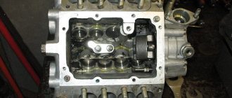
The pump section dispenses and supplies diesel fuel to the nozzles. Each unit includes a frame, a plunger pair, a rotation sleeve, elastic elements of the plunger, a discharge valve and a pusher.
The frame is equipped with a flange that secures the section to the pump using studs. The pin holes are oval in shape; it is possible to adjust the uniformity of diesel supply to each compartment individually (turning clockwise reduces the supply, and vice versa). The plunger pair is directly involved in cutting off and transporting diesel fuel and consists of a sleeve and a plunger. The parts are precision made, the material is steel with the addition of chromium and molybdenum, followed by hardening and cooling with nitrogen. The plunger acts as a piston, has axial drilling and radial grooves that change the flow of diesel fuel. The precision pair of discharge valve and seat are made of steel, after the elements are hardened and cooled. Replacement of components is possible only as an assembly.
KamAZ injection pump cam shaft:
see also
Comments 14
Thanks everyone for the advice. replaced the injection pump assembly.))
maybe you'll see it here. I disassembled the Kamaz injection pump... vk.com/v >
To remove the section you must first remove the rack, remove the top cover there are two racks on each side, unscrew the large nut on the side of the injection pump and pull out the guide, snap the lock on the rack to the side and remove the rack then remove the section if the spring is compressed, turn the pump, change the rubber bands and put them back according to the marks , pump up the swap again, the level may increase through it
Speed control device
The KamAZ Euro 2 fuel injection pump design provides for the use of a speed control mechanism. The fact is that for stable operation of the power plant, a steady state is required. The parameter provides for constant rotation of the shaft, heating of the lubricant, etc. To achieve the indicators, the values of the torsion impulses and counter-motion impulses are equalized. Operation upsets the balance, since the applied force in the modes differs, as a result, the parameter values deviate from the required ones. The return of impaired indicators is possible thanks to adjustment. The process takes place manually (fuel pump rail), or using an automatic machine that regulates the frequency. The last element maintains the user-suggested shaft speed by changing the portion of diesel fuel taking into account the load in automatic mode.
KamAZ engines are equipped with a direct type control device, installed in the frame of the pump with adjustment on the plug.
- A device that sets the required value of the controlled variable;
- Device for perceiving an influencing quantity;
- Comparison device;
- Execution device;
- A device that actuates the regulator.
KamAZ frequency regulator:
Clutch that changes the supply of diesel fuel
The Bosch KamAZ Euro 2 fuel injection pump design and others provide for the introduction of diesel fuel 18° before the piston reaches the top point on the compression stroke. This is done to mix the air and the diesel charge in order to get maximum power.
Increasing the speed of revolutions reduces the time for combustion preparation. To prevent the procedure from starting after the top point and reducing useful work, diesel fuel is administered ahead of schedule, with an increase in angle. This is done with a clutch that changes the supply of diesel fuel by turning the shaft with cams in the direction of circulation in relation to the drive. The clutch improves engine starting and saves diesel fuel.
On KamAZ, the automatic installation uses an adjustment range from 18° to 28°. The product is located at the conical end of the injection pump shaft, fastening is provided by a nut and washer.
The Bosch injection pump coupling consists of:
- skeleton;
- Main half coupling;
- The secondary half of the coupling;
- Gaskets;
- Glass stops of elastic elements;
- Thrust washers;
- Regulating gaskets.
The KamAZ injection pump is a mechanism designed to supply fuel fluid to the cylindrical mechanisms of the engine.
Design and principle of operation
The fuel injection pump device includes such mechanisms as:
- pump compartment housing;
- high pressure fuel pump bearing cover housing;
- inflation hose;
- plunger pair and plunger pusher;
- spring elements;
- mode selection regulator and coarse and fine filters;
- fitting for the fuel drain and injection system;
- fuel injection regulator;
- pressure reducing valve;
- an electromagnetic valve, which is necessary to shut off the fuel supply;
- rack, nozzle and coupling half.
The operating principle of the injection pump is as follows:
- Movement is set from the crankshaft mechanism using a mechanical transmission.
- The rotation of the cam shaft begins. This rotation provokes displacement of the pusher elements.
- The pushers begin to compress special springs.
- The springs cause the plunger to start working and lift it.
- The plunger closes the intake valve and displaces fuel fluid.
- The fuel begins to be sprayed using nozzles.
- The plunger lowers and opens the intake mechanism.
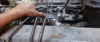
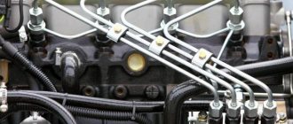
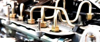
Removing fuel injection pump Kamaz 740
• disconnect the manual control cables for the engine stop lever and the governor control lever, the fuel supply control rod, the fuel supply pipelines to the pump, the outlet and drainage pipelines and the pipeline from the fine fuel filter, the oil supply pipe to the pump, the oil outlet pipe; • unscrew the coupling bolt of the front flange of the driving half-clutch, two bolts of the driven half-clutch (to unscrew the bolts, move them to a convenient position by turning the crankshaft with a crowbar through the holes on the flywheel through the clutch housing hatch); • disconnect the pipelines supplying fuel to the flare plugs, high-pressure pipelines (remove them), the air supply pipe to the auxiliary brake pneumatic cylinder; • unscrew the four bolts securing the fuel pump; • remove the pump.
Malfunctions and repairs
You can repair KamAZ fuel injection pump yourself if you have the necessary tools and equipment.
Main fuel injection pump malfunctions and reasons for their occurrence:
- Water in the fuel mechanism. This breakdown may indicate a malfunction of the fuel filter element, diluted fuel, or a leak in the fuel drives.
- Reduced and uneven supply of working fluid. In this case, it is recommended to check the plunger for damage, and also inspect the discharge valves and rack clamps. The capacity of the injectors should be checked.
- The diesel fuel is running out. The cause of this breakdown may be a leak in the fuel drive. The damaged element should be replaced.
- The drive is tearing. It is recommended to inspect the crankshaft, as well as the main components of the power unit for damage and foreign bodies.
- Delay of the working fluid injection system. Such a malfunction can be caused by damage to the plane of the adjusting bolt of the pusher element, the roller axis and failures in the rotation speed of the cam shaft.
How to remove and disassemble
Removal from engine:
- Remove the terminal from the battery.
- Remove the radiator.
- Remove the vacuum pump.
- Remove the oil dipstick guide pipe.
- Remove the oil filter filter mechanism.
- Turn the crankshaft in the direction of rotation until it stops.
- Disconnect fuel drives.
- Remove the vacuum hose.
- Block the crankshaft from turning.
- Unscrew the bolt in the center of the coupling.
- Remove the chain tensioner.
- Pull out the pump by dismantling the fuel pedal drive.
Disassembling the KamAZ fuel injection pump is done as follows:
- It is necessary to remove the metering type valve from the end of the pump housing. To do this, you need to unscrew the bolts of the pressure plate and release the advance valves of the injection system.
- Then you should remove the fastenings on the top cover.
- You need to disassemble the control board to gain access to the electronics.
- It is necessary to set the required position of the crankshaft.
- Then you need to dismantle the bearing using special equipment.
- At the end, all parts should be washed and their surface polished.
How to add or reduce fuel
Adjusting the Bosch injection pump on KamAZ makes it possible to add fuel, i.e. set the required fuel supply value.
Procedure for reducing fuel:
- Using a key of 13, you need to adjust the air flow to the mechanisms of the power unit. Thanks to this, diesel will be able to mix with air.
- Make adjustments to the corrector and start the motor for testing.
- If necessary, you need to further tighten the air flow until the smoke stops coming out.
In order to add fuel to the KamAZ injection pump (Euro-2 or Euro-3), you need to do the following:
- Tighten the special screws that are located in the upper and side parts of the working fluid supply.
- When unscrewing the bolts, you need to increase the gap for the passage of the combustible mixture. This will help normalize the performance of the power unit and the lubrication system of the high-pressure fuel pump.
- Having increased the diameter of the hole, you should start the engine and check the operation of all systems.
How to install correctly
Installation (installation) of the fuel pump must be carried out using special equipment.
In order to correctly supply and install a high-pressure fuel pump on a KamAZ truck, do the following:
- The vehicle is installed on a special platform.
- Mount the driven clutch onto the advance clutch and secure everything with bolts.
- Turn the coupling so that the bosses of the driven type coupling half are in a horizontal position, and the mark on the end part is in the pointer area.
- Install the flange assembly with the drive coupling half and plate packs. The flange should be located on the left side of the housing.
- Install the fuel pump along with the coupling onto the engine and secure everything with mounting bolts.
- Before tightening the bolts, adjust the flatness of the plate packs by moving the flange along the drive shaft.
- The pump is mounted on a block of cylindrical elements in a vertical position, preventing it from blocking.
- The injection pump sections are connected to the injectors.
- Adjust the advance angle of the injection system.
- Check the presence of oil fluid in the injection pump housing.
- Connect the oil inlet and outlet pipes.
Adjustment of injection pump series 33 KAMAZ produced by YAZDA
Adjusting the injection pump begins with checking and ensuring the installation dimensions. For the correct kinematic position of the levers when assembling the regulator, it is necessary to set the following initial dimensions (Fig. 5.36): Dimension A - the distance from the mating plane of the pump housing to the head of bolt 29 of the nominal flow; A= 55.5 ±0.2 mm. Dimension B is the distance between the point of application of the spring 11 of the regulator and the generatrix of the axis 6 of the levers, B = 52 ±0.5 mm. To correctly set the size, it is necessary to remove the axis 6 by the cap from the pump body and remove the levers 27 and 28 assemblies. Dimension C is the gap between the limiting nut 32 and the pump housing, C = 0.8+1.0 mm. Dimension O - stroke of the anti-corrector rod 10; O = 0.5+0.6 mm. The spring tightening force is controlled during adjustment. Dimension E—stroke of corrector rod 18; E = 0.6+0.8 mm. The spring tightening force is controlled during adjustment.
Fig. 5.36. Diagram of the KAMAZ speed controller: 1 - starting enrichment spring; 2 — injection pump rack; 3 — axis of levers; 4 — spring adjusting bolt; 5 — bolt of minimum rotation speed; 6,9,13,16,20 - nuts; 7 — regulator spring; 8 — anti-corrector spring; 10 — regulator control lever; 11 — corrector rod; 12 — anti-corrector lever; 14 — bolt of maximum rotation speed; 15 — corrector body; 17 — main lever; 18 — intermediate lever; 19 — nominal feed bolt; 21 — starting feed adjustment bolt; 22 — stop lever; 23 — bolt for limiting the travel of the stop lever.
To check the tightness and opening pressure of the injection valves, fuel is supplied to the injection pump head at a pressure of 0.17+0.2 MPa with the position of lever 22 corresponding to the supply being turned off. Fuel leakage from the fuel injection pump drain pipes is not allowed. Otherwise, if the discharge valve spring is in good condition, replace the discharge valve assembly. Gradually increasing the pressure, observe at what pressure the fuel begins to flow out of the drain pipes. If this value does not fall within the limits of 0.9+1.1 MPa, change the discharge valve spring. Adjustment of the geometric angle of the start of fuel supply begins with determining the shape of the cam profile. The angle of start of fuel supply of an injection pump with a symmetrical profile is determined by the moment the fuel begins to move in a momentoscope connected to the pump fitting. In this case, it is necessary that excess pressure be maintained in the injection pump head within the range of 0.04+0.1 MPa. To check the angle, lever 10 is turned until it stops against bolt 14. A torque scope is installed on the fitting of the eighth section, filled with fuel to the angle of height and the shaft drive is turned in the direction of clockwise rotation. At the moment the fuel begins to move, readings are recorded on a graduated disk. Then turn the shaft drive counterclockwise and again record the readings on the graduated disk at the moment the fuel begins to move in the momentoscope tube. The number of degrees contained between the two divisions obtained on the stand’s graduated disk is divided in half and the average value is found. It must coincide with an accuracy of ±0.35° with the table value of the geometric angle of the start of fuel supply (for series 33 the angle is 42.5° with the exception of 33-02, 335 and 335-10 - 40.5°; 33-10 - 41 ,5°). If the obtained value does not correspond to the table value, adjustment is made by changing the thickness of the plunger pusher heel. In an injection pump with an asymmetrical cam profile (for injection pump models 332, 337), the geometric angle of the start of fuel supply by the first section is estimated by the stroke of the plunger from the beginning of its rise to the beginning of fuel injection. To adjust the angle at which the injection pump begins to supply fuel, it is necessary to unscrew the discharge valve fitting, remove it from the seat and install a special device. By turning the stand drive, determine the lower position of the plunger, then, by rotating the cam shaft in accordance with the direction of rotation, set the plunger stroke corresponding to the table value (for models 332, the plunger stroke is 4.85 ± 0.05 mm; 337 - 5.65 ± 0 .05 mm). The angle value corresponding to this position of the cam shaft is recorded on the calibration disk of the stand. Remove the special device and install the discharge valve, spring, pressure fitting and torque scope. By rotating the stand drive clockwise, fill the momentoscope tube with fuel and find the position of the cam shaft at which the fuel supply begins. The corresponding angle value on the calibration disk must coincide with that previously recorded. If necessary, adjust the angle at which fuel supply begins by changing the thickness of the plunger pusher heel. At the moment the eighth section begins to pump fuel, the discrepancy between the marks on the fuel injection pump housing and the fuel injection advance clutch should not exceed 0.5°. Otherwise, caulk the old mark and apply a new one. Place lever 10 against the stop in bolt 14 and gradually increase the rotation speed of the stand shaft. Through the hole for dismantling the rack, record the moment when rack 2 begins to move, corresponding to the start of the regulator’s operation. If the frequency at which the regulator starts to operate does not match the tabulated data, change the position of bolt 14. Set the nominal speed, turn lever 10 until it stops against bolt 14. Measure the cyclic fuel supply and its uniformity between sections. If the cyclic supply does not correspond to the table values, adjust the fuel supply by turning the pump section flange, having previously loosened the high pressure fuel line nut and the flange mounting nuts. The permissible unevenness of the feed between sections is 5% of the value of the nominal cyclic feed. Check the unevenness of fuel supply across sections at 300 min"1. To do this, set the regulator control lever 10 to a position in which the cyclic feed will correspond to 20-30 mm3/cycle. The unevenness of fuel supply across sections should not exceed 35%. Otherwise, replace the discharge valve and plunger pair. Smoothly increase the rotation speed while lever 10 rests on bolt 14. Complete shutdown of the fuel supply should occur at a frequency of 1490+1550 min"1. Otherwise, replace spring 7 of the regulator and begin the adjustment by setting the start of the regulator's action. Adjust the corrector and anti-corrector with the regulator cover removed. To do this, set the rotation speed of the stand drive to 600 rpm, and press lever 17 against the stop against bolt 19. Check the installed gaps with a feeler gauge O = 0.5+0.6 mm. (between the intermediate lever 18 and the anti-corrector lever 12) and E = 0.6+0.8 mm. (between the main lever 17 and the anti-corrector lever 29). Smoothly increase the rotation speed to 900 min”1, in this case the gap O should disappear, and the gap E should not change. At a rotation speed of 1250 rpm1, levers 19, 27 and 28 must be in contact. Otherwise, change the force of the corresponding spring. Change the tightening force of the corrector spring 15 with nut 13, the anti-corrector spring 8 with nut 9. After adjusting the nuts, tighten the cotter pins. Measure the cyclic fuel supply in the corrector and anti-corrector operating modes. If the table data does not correspond, adjust the stroke of the corrector (by turning the housing 15) or the anti-corrector (with nut 6), respectively. After adjustment, check the nominal cyclic fuel supply. At a drive shaft rotation speed of 100 rpm1, turn lever 10 until it stops against bolt 14. In this case, the fuel supply should be 19.5+21 cm3 per 100 cycles. The starting feed is adjusted using bolt 21, turning it out to increase the feed. If the feed is less than permissible, check the condition of the starting spring 1, the ease of movement of the rack 4. Without changing the position of the lever 10, turn the lever 22 until it stops against the bolt 23. When — = rotation speed of the stand drive is equal to 100+150 min"1, screw the bolt 23 until the feed appears fuel, then turn it out 1 turn and lock it. Check for lack of fuel supply throughout the entire speed range of the injection pump. Release lever 10 until it stops against bolt 5. At a drive shaft rotation speed of 300 min'1, the fuel supply should be about 20 mm3/cycle, while complete shutdown of the fuel supply should occur at a frequency of 380+400 min'1. The adjustment is carried out with bolt 5. Install 3 seals: on the screw of the protective cover of the injection pump sections, the bolt of the regulator cover and on bolt 16 of the maximum speed mode (bolt 23 for limiting the travel of the stop lever).