The control circuit operates on direct current. The load limiter VK1 is connected in series with the intermediate relay coil RP1. When the limiter opens, the relay turns off and opens the circuit of the K1 coil and the blocking circuit of the linear contactor.
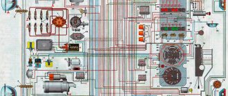
Rice. 1. Electrical diagram of the power circuit and lighting circuit of the KB-60 crane
The LSZ signal lamp lights up when the linear contactor is turned on, and the JIC1 and J1C2 signal lamps light up 30° from the extreme rotation position, “right” and “left,” respectively. The warning lamps are switched on by the contacts of an additional limit switch installed in the rotation mechanism limiter.
The contact closure diagrams of the controllers and the command controller are given in Table. 2, 2, and the list of electrical equipment installed on the crane is in table. 3.
Rice. 2. Electrical diagram of the control circuit of the KB-60 crane
The cargo winch drive uses a brake machine circuit with a continuously adjustable excitation current. The TCTG brake of the boom winch can operate in the main operating mode and in the braking mode. The driver controls the brake by pressing the Kn11 button, or automatically, when the boom approaches the uppermost position, the limit switch VK installed in the reach limiter-indicator is activated.
Table 1 Contact closures of the command controller of the cargo winch of the KB-60 crane
Table 2 List of electrical equipment of the KB-60 crane
Rice. 3. Electrical diagram of the power circuit and lighting circuit of the KB-160.2 crane
The scheme provides the ability to control all mechanisms from the cabin and from a portable installation console during installation and dismantling of the crane.
Rice. 4. Circuit diagram
The peculiarity of the electrical circuit of the KB-405-1 crane is that the drive uses a cargo winch with an AC brake and an electric drive for remote gearbox shifting.
Table 3 List of electrical equipment of the KB-160.2 crane
Rice. 5. Electrical diagram of the power circuit of the KB-405.1 crane
Table 4 Contact closures of the command controller of the cargo winch of the KB-405.1 crane
Table 5 Contact closures of the command controller of the KB-405.1 crane turning mechanism
Table 6 Contact closures of the command controllers for crane movement and boom lifting of the KB-405.1 crane
Rice. 6. Electrical diagram of the control circuits of the KB-405.1 crane
Table 7 List of electrical equipment of the KB-405-1 crane
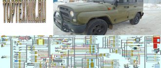
Electrical diagrams of tower cranes
All tower cranes operate from external electrical stationary networks. All electric motors of the mechanism are powered by current. And not only them.
Along with the installation of a tower crane on site, a schematic diagram of electrical power supply is attached to it. It is this that gives a visual representation of how individual components and structural systems powered by electric current interact with each other.
Electrical circuits of tower lifting devices are made in the form of graphic information, where electrical devices, motors, relays, contactors, limiters have verbal symbols. The electrical circuit makes it possible to quickly find a malfunction when a lifting machine is forced to stop and promptly eliminate it. Used when replacing failed electric motors and other consumers of electric current. Allows you to more quickly carry out preventive maintenance and so on.
In principle, a tower crane is so saturated with various electrical devices and components that even a specialist without a diagram finds it difficult to understand everything. For example, each electric motor is controlled using special eclectic devices called controllers. For example, a short-circuited electric motor, which ensures the operation of the boom winch, is controlled using a load carriage controller. To switch the drive from one node to another, a packet HV switch is used.
The electrical equipment of tower cranes is complex. There are so many electric motors. Electric motors are required to lift the load, rotate the lifting mechanism itself, the mounting winch, the movement of the cargo carriage, the hydraulic pusher, and so on.
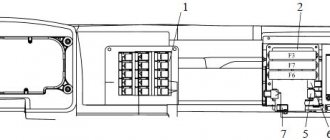
In addition to them, various controllers and travel limiters work. The electrical circuits provide for the presence of about a dozen automatic electrical switches connected to releases. In addition, according to the diagrams, magnetic starters, switches, relays, break relays, limit switches, control buttons, and powerful voltage stabilizers function on the cranes.
And also brake magnets, safety bells, sirens, voltmeters, step-down transformers, ammeters, electric furnaces for heating the cabin, selenium rectifiers, fuses, plug connectors, signal lamps and much more. It becomes obvious that it is simply impossible to do without a circuit diagram.
The safe operation system cannot be located outside the electrical circuit. All mechanisms are equipped with end protection devices. It operates thanks to a linear contactor. In the diagram it looks like this: the contacts of the limit switches of the crane stroke limiting device are connected in series in the circuit of the reverser coils.
The electrical protection circuit includes a graphic designation of a special switch that blocks the doors of the operator's cabin. The cargo winch ensures smooth lowering of the load using a back-up system. It is controlled directly by the operator using a pedal. And so on.
The absence of electrical circuits at the workplace can lead to prolonged stoppages of a productive lifting machine. And this is a huge loss of money, which is extremely unprofitable for business. The operator must read electrical circuit diagrams well because this is the key to good operation of lifting machines.
— all about special equipment!
KB-408.21
| Total crane weight (in working condition), t | 95,2 |
| Maximum load capacity, t | 10,0 |
| Load capacity at maximum boom reach, t | 6,0 |
| Boom radius, m | 6,0-30,0 |
| Reach at maximum load capacity, m | 16,0 |
| Load moment, (kNm) tm | 160,0 |
| Maximum lifting height, m (horizontal boom/oblique boom) | 46,6 / 57,8 |
| Total electric power engines, kW | 123,6 |
| Lowering depth, m | 5,0 |
| Tower crane rotation speed, rpm | 0,65 |
| Structural weight of the crane, t | 54,8 |
| Load lifting speed max. mass, m/min | 36,0 |
| Maximum load lifting speed, m/min | 67,0 |
| Speed of smooth loading of cargo, m/min | 4,8 |
| Load trolley travel speed, m/min horizontal boom/inclined boom | 7,0 / 30,0 |
| Crane travel speed, m/min | 18,0 |
| Base, m | 6,0 |
| Track, m | 6,0 |
| Rear clearance, m | 4,35 |
| Minimum radius of curvature of the track (inner rail), m | 12,0 |
Scope of application
Cranes of the KB-403 type are particularly popular and the most widely used among other special lifting machines. They are used on large construction sites and facilities that require large volumes of construction or installation work, speed and high productivity:
- In the construction of residential or administrative buildings.
- On the construction of large industrial complexes.
INTERESTING! KB-403 is capable of performing absolutely all work on lifting any cargo on site, which allows significant savings on the use of additional lifting equipment.
kran-el.ru KB 309HL E3 Crane KB 309HL Electrical circuit diagram
Transcript
1 contacts must open Pos. Designation RB RUV RU1-RU3 RU RMV RMP RTS, RT RTP RT OGP VPS, VPP VSS VP VLV, VPV VV, VN VG Z2 B1N B2N KV Adjustment data for circuit elements Actuation pattern of relays, sensors and switches 0.3 0.s 0, 0.8 s The relay armature drops 0.8 1.0 s with a time delay of 3.0 s the relay contact opens 270% I NDV MV at a current of 280% I NDV MP1 The relays should operate when the braked motors are turned on 20 60 s after: s (from cold state) The relay armature is retracted at a current of 3.6 3.9 A When the load on the hook is 10% more than the nameplate When the boom is raised to its highest position When the boom is lowered to the maximum reach position When the hook approaches the boom up to 600 mm When the crane is turned to 0 from neutral When when the crane approaches the dead-end stops When switching from 2-fold to -x-fold suspension reeving, the contact must open at a wind speed of over 18 m/sec. In the power cabinet, the contacts are closed below +1 C at air temperature: In the crane cabin Below C, contact 3- must close when a three-phase voltage is supplied with a direct phase sequence of the permissible value Pos. designation RB RK RP1 RP2 RP3 RP Table of starting-braking resistors Marking of terminals Stage resistance Ohm VR1-VR, VR2-VR, VR3-VR6 0.9 VR-VR7, VR-VR8, VR6-VR9 1.6 VR7-VR10, VR8-VR11 ,VR9-VR11 VR10-VR13, VR11-VR13, VR12-VR R1-2R1, 1R2-2R2, 1R3-2R3 1.06 2R1-3R1, 2R2-3R2, 2R3-3R3 0.2 R1-R11, R2-R21 , P3-P31 0.06 P11-P12, P21-P22, P31-P32 0.179 P12-P13, P22-P23, P32-P33 0.23 P13-P1, P23-P2, P33-P3 0.8 P1-P3 , P2-P3, P3-P3 0, , , ,0 Fuse characteristics (A) Pos. designation Parameters Pr1 Pr2 F2 F3 F F6 F7 F8 F9 Load 2 1, Fuse link Design. Checked by Refetsenz. N. ontr. Approved Valid from 2131, 2292, 276, 288 document. Signature Date B 309ХЛ E3 ran B 309ХЛ Electrical circuit diagram Lit. ov 1 6 Alexander Nazarenko
2 A3 P PP R 3 A2 3 C2 1 VA2 nl L M 1SA1 3SA1 2SA1 SA M 17 P 190 nl2 OGP VM-S OGP RM VPP VP P1 VV VG SS PS SA1 VM-P VM-S VM- VMV RV M 28 VM - BM-B a SA1 2SA RT VN RTP VPV VLV 3SA1 3SA1 LV PV T np VPS VSS SB T 2 2 M LV V RU PV RTS EL1 UL N KV 69M SS PS PP L RL1 PP P R P R PS SS RU RB T U V N PV LV UV1 VM-V RUV PV 2 3 Vp UV3 9 n1 V1A L TURN MOVEMENT WOUND ARROW NV 103 LV PV 10 document. Signature Date 2
3 VM-P 1 RU1 U RU2 LIFT SS LIFT 7 1SA1 M SS RT RB M S1 RB RU RT P1 PP TP RP 62 P1 S RB D RU2 RU3 RP RU3 RP RU3 S1 RP D RUV RP TP EmTP TP R P S2 RU1 P TP P2 U2 S2 3 0 Document lifting mechanism. Signature Date 3
4 C V3 A3 AB VV SV MV UV3 UV1 UV1 PV VP1 VP2 VP3 UV3 VP VP VP6 VP7 VP8 UV3 RMV EmTV RMP LV RK V RT U M1 M2 R1 R3 VP10 VP12 Rotate P1 A RK B 3Р2 С6 3Р3 RK N AS BC SS MS EmTS 2Р1 2Р2 2Р3 Р12 VP9 Р13 VP11 S У А6 С7 А3 В3 С3 А7 С8 R e l a PS SS P2 S2 RTS RTP S P P S VD 7 U2 VP1 AP1 7 R1 Mechanism TRANSMISSION LOWER P11 document. Signature Date RP1 R21 R22 R23 RP V3 RP2 MP1 S U2 R2 R2 6.2 SP1 RP3 R31 R32 R33 R3 D RP U2 R3 R3 6 AP2 VP2 SP2 8 MP2 VP1 VP2 Cargo winch a 8 RT A3 B3 C3
5 A1 B1 C A2 132 A1 F2 F3 BA3 KTB K1 K F6 F7 F9 F8 1SA1 3SA1 F R3M RM V Tr1 (BT1) RP R1P 2HL2 EK1 E EK 1HL1 3HL2 3HL1 2HL1 HL EKK R2P R7P K R3P nf R1E R1A R1M (BT2) V8 R9П R6П R10П Cabinet heating Cabin heating Heating boost Lifting Brake moving Engine moving Turn Reach Scale backlight R2Э K R2M B2N 306 T (RT1) (BT3) (BT) Р3 RP K1 R3H RH K1 М 2 V9 (RT2) (RT3) V ВД1 ВД2 ВД2 Turn brake ВД1 18 E1F E2F S1H Pr1 ШР2 V1 R3Э (BT) R8П R1H R1V V6 K V11 V12 KK V7 R2H S1 S2 E1M S1 FCO n Zv 318 ШР V1 CO1 Z2 B1N T Pr2 V16 MCO T R2A Zv RCO TR M 30 NN E3M E1H O K1 V17 ВСО ВСО N Cabin temperature regulator Heating boost Heated windows Cabin canopy R3М-left panel RM-right panel El. Oven 1 R1M-rear wall panel R2M-rear right panel R1V fan heater TEN and 9 TEN 2 and 7 Floor heating TEN 1 and 6 TEN and 8 TEN 3 and 10 Oven 2 TEN cabinet Panels (R1H, R2H) and Lamps heaters Power cabinet Spotlights booms Tower spotlight Cabin light Bell Temperature regulator Cabinet circuits Transformer 220/12V Sockets 12V Rectifier 12V Windshield wiper document. Signature Date
6 L A2B B2B C2V OGP VD1 R9 R10 EmT1 RR R1 R EmT2 Text Text ARC VT1 Vp V2SU VT3 Text Rd C1 KV (P.8) ma Vp R12 R13 DUS VT2 R2 R3 VD2 Text VD3 C3 R1 R16 R11 09 N A2 B2 C2 R VT C2 VT7 VT6 08 VT VД 01 R R8 C1 R12 VД 22 (Item 3) SF 8.0 Rope reeling 2 char. Load characteristics of the crane Load capacity, t. 8.0 7, 7.0 6, 6.0 7.3, 12,, , ,0 6.6 6.3.9 1st load Characteristics,7 Rope reeling 1 - load characteristics 2 characteristics. N E VA1 L3 C1 Force sensor (DS) A1 B1 C1 C2 VU L A B C 0, 23 R,2 2, VTB TP Text N 16 C2 Hour meter SM Crane load limiter document. Signature Date 6
7 Section Diagram on - Position of the handle so you Estimated speed of lifting and lowering the load Mass of the load on the hook Position (numerator-1char., denominator-2char.) of the handle Empty hook 1t 3t t 8t pos. descent 3, 3.7 36.2 36.8 16.6 16.6 16.7 16.7 16.8 3rd pos. descent, 3 18, 2 28, ,, ,7 16.8 1st pos. descent 2.6 3.0 3.8.6 1.3 1, 1.6 1.7 1.9 1st pos. rise 11, 10 7,3,9 6,0,7,1, 3,6 2nd pos. rise 32.6 26.0 18.1 8.3 16, .7 3rd pos. rise 3, 3.1 3.6 33, 16.3 16.2 1.9 1.6 1.3 document. Signature Date 7
8 Useful links 1. Technical documentation in Visio. Libraries of symbols for symbols of elements of electrical and engineering circuits will allow you to easily and quickly draw any circuits in accordance with the requirements of Russian (GOST, GOST ME) and international (IEC) Electricity and circuit standards. Regulatory, reference information on symbols of elements of electrical circuits and engineering systems; Electrical diagrams; Reference information on electrical devices, wound electrical equipment. Technical and regulatory documentation for electrical equipment of lifting cranes; Electrical circuit diagrams of load-lifting cranes; Reference information on electrical equipment of load-lifting cranes.