Adjusting valves on the D-240 engine
The valve clearance must be adjusted when the engine is cold. For the D-240 engine, the gap in the intake valves is 0.25 mm, for the exhaust valves - 0.30 mm.
Rice. Checking and adjusting diesel clearances: 1-lock nut, 2-adjusting screw, 3-feeler gauge, 4-rocker arm striker, 5-valve stem.
1. Clean the cap and cylinder head cover from dirt and dust so that there are no oily deposits on the outer surface.
2. Remove the lid cap and wash it in kerosene.
3. Unscrew the installation bolt and insert its opposite end into the hole in the flywheel housing.
4. Check the fastenings of the rocker arm shaft supports and, if necessary, tighten them.
5. Install the KI-9918 device on the intake valve spring plate, releasing the release cam of the movable carriage. The movable carriage of the device, under the action of a spring, should rest against the striker of the rocker arm.
6. Press the rocker until the striker stops at the end of the carriage rod and set the indicator arrow to zero.
7. If the gap does not meet the permissible limits, adjust the valve mechanism according to the readings of the device indicator by screwing in or unscrewing the adjusting screw, having first unscrewed its lock nut.
8. Turning the crankshaft 1/2 turn, check and, if necessary, adjust the clearances in the third, fourth and second cylinders, respectively.
9. Screw the clamp into the hole in the flywheel housing. Install the removed components onto the engine.
If the KI-9918 device is not available, perform the following steps after the fourth point:
1. Set the piston of the first cylinder to the position corresponding to the end of the compression stroke (both valves are closed).
2. Loosen the locknut of the adjusting screw on the valve rocker arm and, screwing in the screw, use a feeler gauge to set the required gap between the rocker arm striker and the end of the valve.
3. Tighten the locknut securely and check the gap again with a feeler gauge, turning the pusher rod around its axis.
4. Upon completion of adjusting the valves of the first cylinder, turn the crankshaft clockwise half a turn (180°) and begin setting the clearance in the valves of the third cylinder. The gaps are adjusted in a sequence corresponding to the operating order of the diesel cylinders (1-3-4-2).
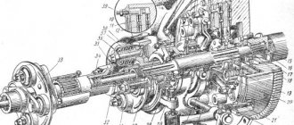
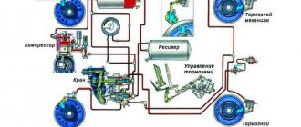
Adjustment and maintenance of steering control of MTZ-82 tractors
Safety, quality of work and driver fatigue largely depend on the condition of the steering control of the MTZ tractor. Therefore, steering maintenance must be carried out especially carefully. Maintenance of the steering control of the MTZ-80, MTZ-82 tractor consists of periodically monitoring the oil level in the power steering housing and replacing it, lubricating the cardan joints of the MTZ steering drive, monitoring the condition of the threaded connections of the steering drive and steering rods, bipod and swing arms, sector fastenings, checking and adjusting the free play of the steering wheel.
The steering column of the MTZ tractor must be adjusted to eliminate possible vibrations on the steering wheel. To do this, tighten nut 12 by hand (see Fig. 1) until the latter comes into contact with sleeve 10. In this case, the gaps in the connections must be selected. Then unscrew nut 12 one and a half turns and lock it with nut 13.
Rice. 1. Steering gear drive for MTZ-82 tractors
1 - splined bushing; 2 - front shaft; 3, 7 — cardan joints; 4 - intermediate support; 5 - middle shaft; 6 - stand; 8 — pin; 9, 12 — nuts; 10 - bushing; 11 — shock absorber; 13 - lock nut; 14 — steering wheel; 15 — handwheel; 16 — steering shaft; 17, 21 — screws; 18 — intermediate shaft; 19 — steering column pipe; 20 — earring; 22 — right wall stand; 23 - retainer; 24 - spring; 25 – handle
The oil filter is washed in the following sequence:
Raise the lining. Disconnect the oil supply line 12 (see Fig. 2) from the cover 11 of the pressure reducing valve 14. Remove the cover, for which you first unscrew the two bolts securing it to the body 22, and then, using them as dismantling ones, screw the bolts into the dismantling holes of the cover and take it off. Disconnect the remaining oil lines from pressure reducing valve 14. Holding filter 13 with your hand, unscrew the pressure reducing valve and remove the drain filter. Wash the filter in diesel fuel.
Rice. 2. Power steering for MTZ-82 tractors
1 - plug; 2 valve cover; 3 valve adjustment screw; 4 worm; 5 — bolt for fastening the adjusting sleeve; 6 — adjusting sleeve; 7 - sector; 8 - nut; 9 - rack; 10 — adjusting bolt; 11 — top cover; 12 - nut; 13 — drain filter; 14 - pressure reducing valve; 15 — ABD control valve; 16 — differential lock sensor spool; 17 — control valve handwheel; 18 — bipod; 19 — bipod nut; 20 - drain plug; 21 - rotary shaft; 22 — body; 23 — rack stop; 24 — adjusting shims; 25 - rod; 26 - piston; 27 — front cylinder cover; 28 — thrust bearing; 29 — washer; 30 - spherical nut; 31 - spool
To install the filter, perform the operations in reverse order:
The filter is washed at TO-3 (960-1000 operating hours). At the same time, you need to tighten the nut 8 securing the sector on the rotary shaft.
In the MTZ-82 hydraulic booster the following is regulated:
worm-sector and sector-rack engagement, tightening of the worm nut, axial travel of the rotary shaft, safety valve, as well as control of the differential lock valve.
The worm-sector engagement and the tightening of the worm nut are adjusted in the following sequence. Jack up the tractor so that the front wheels do not touch the ground. Then loosen the tightening of the adjusting bolt 5, insert a key into the groove of the sleeve 6 and turn it clockwise until the teeth of the worm and the sector stop (in this case, the bipod 18 should be in the middle position). The bushing is turned counterclockwise so that it rotates 10-12 mm along its outer diameter. Tighten bolt 5. Start the engine and check that there are no jams in the “worm-sector” engagement when turning the steering wheel in both directions until it stops. If jamming occurs, then you need to increase the gap in the engagement by releasing bolt 5 and turning sleeve 6 additionally clockwise. The force on the steering wheel should not exceed 30-40 N. Adjusting the tightening of the spherical nut 30 of the worm consists of correctly tightening the thrust ball bearings 28 to ensure that the ends of the spool 31 are normally pressed by the bearing rings. The proper operation of the hydraulic booster largely depends on this adjustment. Excessive tightening of nut 30 may cause spool misalignment and increased turning force. The gaps between the bearings and the spool lead to an increase in the free play of the steering wheel, as well as to vibrations of the wheels, since under these conditions the spool can move arbitrarily, accordingly changing the direction of oil flow into one or the other cavity of the piston cylinder. Before tightening the nuts 30, unscrew the four distributor mounting bolts , remove cover 29. Fasten the distributor with two diametrically located bolts to the hydraulic booster housing, placing a set of washers (or nut) under the heads of the bolts, the thickness (or height) of which is equal to the thickness of the cover flange 29. Tighten, having previously uncottered, the nut with a torque of 20 Nm . In this case, the bearing rings 28 must be tightly pressed to the ends of the spool 31. Then unscrew the nut 1/10-1/12 of a turn to align the slot of the nut for the cotter pin and the hole in the worm, and cotter the nut. Unscrew the two bolts screwed into the housing, replace the cover 29 and secure the distributor. The sector-rack engagement is adjusted by shims 24 under the flange of the rack stop 23. In this case, the gap between the stop and the rail 9 should be 0.1-0.3 mm. When checking this gap, you need to press the rack 9 towards sector 7. The axial stroke of the rotary shaft of the MTZ tractor is adjusted in the following sequence: loosen the locknut and screw the adjusting screw 10 all the way into the end of the shaft. Then unscrew the bolt 10 pa 1/8-1/10 turn and lock it with a nut. The safety valve is checked as follows. Instead of plug 1, a pressure gauge with a division scale from 0 to 10 MPa is connected to the discharge line or to the valve cover. Start the engine and turn the steering wheel from one extreme position to the other. At maximum rotation speed of the diesel crankshaft, bring the oil temperature in the hydraulic system of the MTZ tractor to 50±5°C. In this case, the pressure should reach 8.8 MPa. If the pressure gauge readings are less, increase the pressure to the required values by slowly screwing in screw 3. After adjustment, screw 3 must be secured with a nut and the cap installed. A sign of a maladjustment of the safety valve is an increase in force on the steering wheel. The free play of the steering wheel is checked when parked with the engine running. However, it should not exceed 20°. If the free play of the steering wheel is greater, check the gaps in the connections of the steering drive and, if necessary, tighten the nuts securing the bipod and sector, fastening the swing arms of the front axles and steering linkage joints, tightening the worm nut, adjusting the “worm-sector”, “sector-rack” engagement. and axial travel of the hydraulic booster rotary shaft. It is necessary to regularly monitor the oil level in the hydraulic steering system of the MTZ tractor. If the oil level is below the lower mark on the oil gauge, operating the tractor is strictly prohibited. When changing the oil, the filler filter must be washed at the same time. After changing the oil, pump the hydraulic steering system of the MTZ tractor in the following order:
Jack up the front axle until the front wheels lift off the ground. Start the engine and, at a low engine speed, turn the steering wheel to its extreme positions 8-10 times (first slowly, then quickly), without holding it in its extreme positions. Then check the oil level and, if necessary, add it to the upper mark of the oil gauge. The distributor of the MTZ tractor has to be removed and reinstalled if its sealing rings are replaced and parts are washed.
When installing the distributor, do the following. Check the presence of sealing rings at the ends of the distributor and the position of spool 31 in its body. The spool must be installed so that its chamfered end along the outer diameter is directed towards the power steering housing. Setting the spool in the opposite direction will result in a sharp increase in turning force. Install the distributor of the MTZ tractor without the outer cover 29 and attach it to the body of the MTZ hydraulic booster with two diametrically located bolts, placing a set of washers under the heads of the bolts, the thickness of which is equal to the height of the cover. Install the thrust bearing 28, a washer with a cone and tighten the spherical nut 30 in accordance with the recommendations given above.
A sign of correct tightening of the nut is the absence of gaps between the spool and the bearing rings and the steering wheel recoil (return of the spool to the neutral position) after it stops rotating to the left.
refac.ru
Which gasket material is better?
Gaskets made of different materials
When replacing a gasket, many car owners have a reasonable question: which gasket is better - metal or paronite? Each of these materials has its own advantages and disadvantages. At the same time, you need to understand that if the manufacturer recommends using gaskets made of a certain material, then you must adhere to these requirements.
As a rule, a metal gasket is stronger than its paronite counterpart. Therefore, it is advisable to install it on powerful turbocharged or forced engines. If you do not plan to tune the engine of your car, but simply operate it in a gentle mode, then the choice of material does not matter much to you. Accordingly, a paronite gasket is quite suitable. Moreover, this material is more flexible and is able to adhere more tightly to work surfaces.
Also, when choosing, it is necessary to take into account that the material from which the gasket is made does not have a primary impact on its service life. A much more important indicator is how the gasket was installed. The fact is that there are very thin walls between the individual groups of holes. Therefore, if the gasket is not installed exactly in the seat, then there is a high probability of burnout even in the strongest material.
The most obvious sign that the gasket was installed incorrectly is its rapid failure. Also, if you installed it incorrectly, the car may simply not start. In diesel engines, the knocking of the pistons may also be heard. This happens because the piston touches the edge of the gasket.
Conclusion
If you have a broken cylinder head gasket, then it is not advisable to drive a faulty car . Therefore, we recommend that if you discover a gasket break, replace it immediately. In addition, it is important not only to detect the very fact that it is broken, but also the reason for this. In particular, why the engine overheats or other malfunctions occur.
During the replacement process, monitor the torque on the mounting bolts. Timely replacement of the cylinder head gasket will save you from large financial expenses on repairing more expensive components. The longer you drive a car with a blown cylinder head gasket, the more likely it is that other, more expensive and important engine components will fail.
«>
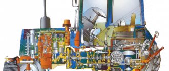
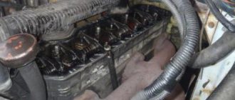
Cylinder block and valves of the D-243 engine
________________________________________________________________________
Cylinder block and valves of the D-243 engine
Cylinder head D-243
The cylinder head of the D-243 engine of the MTZ-82 tractor is a cast iron casting, in the internal cavities of which there are inlet and outlet channels closed by valves. To ensure heat removal, the cylinder head has internal cavities in which coolant circulates. On top of the cylinder head are mounted struts, a rocker arm axle with rocker arms, a head cover, an intake manifold and a cover cap that covers the valve mechanism.
On the fuel pump side, four injectors are installed in the head of the MTZ-82 engine block, and on the generator side, an exhaust manifold is attached to the head. To seal the connector between the head and the cylinder block, a gasket made of asbestos or non-asbestos sheet reinforced with perforated steel sheet is installed. The holes for the cylinder liners and the oil channel are edged with steel shells.
Checking the tightness of the bolts securing the D-243 cylinder head
Check the tightening of the mounting bolts for the D-243 cylinder head of the MTZ-82 tractor at the end of the run-in and after 1000 hours of operation on a warm diesel engine in the following order:
- remove the cap and cylinder head cover; - remove the rocker arm axle with rocker arms and struts; - using a torque wrench, check the tightness of all cylinder head mounting bolts in the sequence shown in Figure 19, and, if necessary, tighten them. Tightening torque -200±10 Nm.
After checking the tightness of the cylinder head bolts of the MTZ-82 engine, reinstall the rocker arm axle and adjust the gap between the valves and rocker arms.
Diagram of the sequence of tightening the cylinder head bolts of the D-243 engine
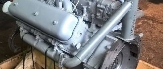
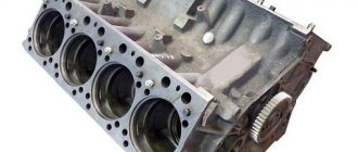
D-243 engine cylinder block
The D-243 cylinder block is the main body part of a diesel engine and is a rigid cast iron casting. Four removable sleeves made of special cast iron are installed in the vertical bores of the block.
The liner is installed in the cylinder block of the MTZ-82 engine along two centering belts: upper and lower. In the upper belt the liner is secured with a collar, in the lower belt it is sealed with two rubber rings placed in the grooves of the cylinder block. The sleeves are sorted into three size groups according to their internal diameter: large (B), medium (C) and small (M). The group marking is applied to the lead-in cone of the cartridge case.
It is necessary to install sleeves of the D-243 block of the same size group. Coolant circulates between the walls of the cylinder block and the liners. The end walls and transverse partitions of the cylinder block have bosses designed to form supports for the crankshaft. Covers are installed on these tides. The bosses together with the covers form beds for the main bearings. The beds for the main bearing shells are bored out from one installation complete with the main bearing caps. Changing covers is not allowed.
The D-243 cylinder block has a longitudinal channel, from which oil flows through transverse channels to the main bearings of the crankshaft and camshaft bearings. On the outer surfaces of the cylinder block there are machined mating surfaces for attaching a centrifugal oil filter, water pump, coarse and fine fuel filters, and oil filler neck.
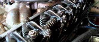
Timing timing mechanism D-243
The gas distribution mechanism of the D-243 engine of the MTZ-82 tractor consists of a camshaft, intake and exhaust valves, as well as parts for their installation and drive: pushers, rods, rocker arms, adjusting screws with nuts, plates with crackers, springs, struts and rocker arm axles.
The D-243 camshaft is three-bearing, driven from the crankshaft through the distribution gear. The camshaft bearings are three bushings pressed into the block bores. The front bushing (from the fan side) is made of aluminum alloy, has a thrust collar that holds the camshaft from axial movement, the remaining bushings are cast iron.
The pushers of the D-243 engine are steel. The working surface of the pusher plate is overlaid with bleached cast iron and has a spherical surface of large radius (750 mm). As a result of the fact that the camshaft cams are made with a small cone, the tappets perform a rotational movement during operation.
The push rods are made of steel rod. The spherical part that goes inside the pusher and the rod cup are hardened. The rocker arms of the MTZ-82 engine valves are made of steel and swing on an axis mounted on four racks. The outer pillars are of increased rigidity. The rocker axis is hollow and has eight radial holes for lubrication of the rocker arms. The movement of the rocker arms along the axis is limited by spacer springs.
Inlet and exhaust valves D-243 are made of heat-resistant steel. They move in guide bushings pressed into the cylinder head. Each D-243 valve closes under the action of two springs: external and internal, which act on the valve through a plate and crackers.
Sealing collars installed on the valve guides prevent oil from entering the diesel cylinders and exhaust manifold through the gaps between the valve stems and the guides.
Checking the gap between valves and rocker arms of the D-243 engine
Check the gaps between the valves and rocker arms of the D-243 engine and, if necessary, adjust every 500 hours of operation, as well as after removing the cylinder head, tightening the cylinder head bolts and when valve knocking occurs. The gap between the rocker arm striker and the end of the valve stem when checking on an unheated diesel engine (water and oil temperature should be no more than 60 ºС) should be:
For the D-243 engine and its modifications: - intake and exhaust valves - 0.25 mm (+0.10 -0.05) When adjusting the gap between the end of the valve stem and the rocker striker on a cold diesel engine, set: intake and exhaust valves - 0 .25 mm (-0.05)
Adjust the valves of the D-243 engine in the following sequence:
- remove the cylinder head cover cap and check the fastening of the rocker arm axis struts; - turn the crankshaft of the MTZ-82 engine until the valves in the first cylinder overlap (the inlet valve of the first cylinder begins to open, and the exhaust valve finishes closing) and adjust the clearances in the fourth, sixth, seventh and eighth valves (counting from the fan), then turn the crankshaft one revolution, setting the overlap in the fourth cylinder, and adjust the clearances in the first, second, third and fifth valves.
To adjust the gap, loosen the lock nut of the screw on the rocker arm of the adjustable valve and, turning the screw, set the required gap using the feeler gauge between the rocker arm striker and the end of the valve stem. After setting the gap, tighten the lock nut. After adjusting the valve clearance, replace the cylinder head cover cap.
________________________________________________________________________
________________________________________________________________________
________________________________________________________________________
________________________________________________________________________
techspez.ru
Do-it-yourself valve adjustment d 240
Adjusting valves d 240 will become easier if you first understand their purpose and design.
Valves are extremely important elements in the engine that are responsible for allowing air into the cylinders. Combustion products are also removed through them.
Both valves, intake and exhaust, are made from steel alloys that are resistant to high temperatures. The part of the valve that is responsible for the seal is made of nickel alloys. The exhaust valve disc is only 6 millimeters smaller than the intake valve disc. These devices themselves are located in bushings made of several metals. They are tightly attached to the cylinder head in the engine.
The valves are pressed using springs. In a cold engine, valve clearances should not exceed 0.25 mm.
Do-it-yourself valve adjustment d 240
And so to work...
- Ideally, valve adjustments should be carried out every 20 days (480 hours) of engine operation. The adjustment procedure is always the same.
- First you need to remove the cap located on the cylinder head cover.
- After this, you need to make sure that the fastenings of the rocker shaft posts are sufficiently tightened. The piston in the first cylinder must be moved to the position corresponding to top dead center.
- Once this is done, the inlet and outlet valves must be closed. Having gained full access to the valves, you need to unscrew the locknut on the rocker arm mount of the valve that needs to be adjusted, but you should not remove it - just loosen it.
- After this, you can adjust the gap using a screw; you can measure the size of the gap using a feeler gauge. Having completed the adjustment, you need to reassemble the device in the reverse order, making sure that the gap has not changed during assembly.
- When adjusting valves d 240, you must remember that this procedure should be carried out in strict sequence. It fully corresponds to the order in which diesel engines operate - 1-3-4-2. By turning the crankshaft half a turn clockwise, you can work with valves that have not yet been adjusted. After the procedure is completed, it is necessary to check the operation of the valves by starting the engines.
autochauffeur.ru
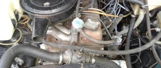
How to find out if the cylinder head gasket is blown
You can determine whether the cylinder head gasket is blown by using one of several methods. In this case, diagnostics are simple and can be done by anyone, even a novice and inexperienced driver.
To check the integrity of the gasket, you must do one of the following:
- With the engine running, visually inspect whether smoke is coming from the gap between the cylinder head and the cylinder head . Also listen to see if there are loud ringing sounds coming from there that were not there before.
- Inspect the surfaces of the radiator caps and expansion tank of the cooling system, as well as the neck for filling oil into the engine. To do this, you just need to unscrew them and visually inspect them. If antifreeze gets into the engine, there will be a reddish emulsion on the oil filler cap. If oil gets into the antifreeze, then there will be oily deposits on the radiator or expansion tank caps.
White smoke from the exhaust pipe
How to check a cylinder head gasket using a condom
One of the effective and popular testing methods is the method using a balloon or a condom. It is put on the neck of the expansion tank, having first unscrewed the cap. The main thing is that the condom sits tightly on the neck and provides a tight seal (instead of a condom, you can use a bag or a balloon, but the diameter of the condom is usually ideal for the neck of the tank). After you put it on the reservoir, you need to start the engine and let it run for a few minutes at 3.5 thousand rpm. Depending on the level of depressurization, the condom will fill with gases quickly or slowly. It depends on the specific situation. In any case, if it begins to fill with exhaust gases, this means that the cylinder head gasket is broken.
Checking the cylinder head gasket with a condom
Checking the gasket with a bottle
Another method for determining whether the cylinder head gasket is broken is often used on trucks . To do this, it is enough to have a small bottle of water (for example, 0.5 liters). As a rule, expansion tanks have a breather (a tube that helps maintain the same pressure as atmospheric pressure in a closed container). The method is very simple. With the engine running, place the end of the breather in a container of water. If the gasket is broken, air bubbles will begin to come out of the tube. If they are not there, then everything is in order with the gasket. If at the same time coolant begins to appear from the breather, this also means that everything is in order with the gasket.
Checking the cylinder head gasket on trucks
Testing with a bottle
The two methods described above are suitable for diagnosing a malfunction when exhaust gases break into the cooling jacket. These methods are very effective and have been used by motorists for decades.
MTZ diesel adjustments.
| Oil pressure in the lubrication system on a heated diesel engine at rated crankshaft speed, kg/cm2, (MPa) | 2,0-3,0(0,2-0,3) |
| Deflection of the fan belt branch located between the generator and crankshaft pulleys, when pressed with a force of 4 kgf (40 N), mm | 15-20 |
| Recommended diesel coolant temperature (thermal mode), degrees | 75-95 |
| Gap between the rocker arm striker and the end of the valve stem on an unheated diesel engine, mm | 0,25-0,30 |
| Pressure at the start of fuel injection by the nozzle (pressure at the start of lifting the nozzle needle), kgf*cm2 (MPa) | FD-22 175+5(17.5+0.5) FD-22M 178+7(17.8+0.7) |
| Advance angle of fuel supply by the fuel pump (nominal to TDC), deg | 23-25 20 (with fuel pump ND-21/4) |
| Tightening torque, kgf*m (N*m): | |
| main bearing bolts | 20-22 (200-220) |
| cylinder head bolts | 19-21 (190-210) |
| cylinder head fastening nuts D-240 | 18-20 (180-200) |
| connecting rod bearing nuts | 16-18 (160-180) |
| flywheel mounting bolts | 18-20 (180-200) |
| crankshaft pulley bolt | 10,5424-28 (240-280) |
| crankshaft counterweight bolts | 12-14 (120-140) |
| injector mounting bolts | 2-2,5 (20-25) |
traktormtz80.narod.ru
Cylinder head tightening order and tightening force
The mounting bolts are tightened with a torque tool in accordance with the diagram given in the technical documentation. The algorithm for tightening the head bolts is identical for naturally aspirated engines and units equipped with supercharging. The fasteners are first tightened with a force of 70-90 N/m, and then the second stage of fixation is carried out with a torque of 170-190 N/m (step-by-step tightening is used only for the diesel version with a turbocharger). Between steps there is a pause of 5-6 minutes, necessary for uniform deformation of the gasket.
The procedure for tightening the cylinder heads of engines D-240, D-243, D-245
The final fixation of the parts is carried out with a force of 190-210 N/m (atmospheric model) or 230-250 N/m (supercharged version); applying more force is strictly prohibited.
If at least 1 fastening element rotates in the body of the block or the rod breaks (or the head breaks), then you will need to dismantle the head and restore the thread. Operation of the motor with a damaged head mounting element is not allowed.