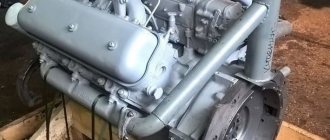
MTZ tractor engines are equipped with a removable head, which is installed on the cylinder block and secured with bolts. The reliability of the power unit depends on the correct installation of parts and compliance with the tightening torque of the MTZ cylinder head. When exhaust gases or coolant break through, power is reduced and components of the piston group and gas distribution mechanism of the engine are destroyed.
All MTZ tractor engines have a removable head.
Replacing the cylinder head assembly
If the valves do not fit tightly to the seats or a metallic knock is heard that cannot be eliminated by adjusting the valves, water has entered the combustion chamber, or the valves sink beyond the permissible limits, then the cylinder head must be removed from the engine for repair. The sinking of valves without removing the cylinder head is determined by the protrusion of their rods relative to the surface of the cylinder head. To do this, install the pistons alternately in the V.M.T. on the compression stroke and measure the distance from the surface of the head to the end of the valve stem with a depth gauge. If the protrusion of the valve stem is more than 57.2 mm, then the head is removed and repaired. The normal value of valve stem protrusion is 56 mm, the maximum value is 58.4 mm.
Control, re-tightening of the cylinder head
The control stretching is carried out after running-in of the power unit, a routine check is performed after 1000 hours of diesel operation. To carry out the work, you will need to remove the upper protective casing of the gas distribution mechanism and dismantle the roller with rocker arms. Checking the tightening is carried out according to the diagram available in the operating instructions. For testing, a torque wrench is used, the applied torque is 190-210 N/m.
After broaching, it is necessary to install the removed parts of the cylinder head in their original places, and then check the correctness of the gap between the rocker arm and the end of the valve stem. For atmospheric power units, the clearance for the intake and exhaust valves is 0.20-0.35 mm (on a warm unit). When setting up a cold diesel engine, it is recommended to set the distance within 0.20-0.25 mm. MTZ engines equipped with a compressor differ in the size of the gaps (0.25 mm for the intake tract and 0.45 mm for the exhaust tract).
The valve mechanism is adjusted by rotating the screw (after unscrewing the locking nut) starting from the first cylinder (from the pulley). To correctly set the gap, the piston is set to the position of the upper extreme point (determined by the moment the valves overlap). After setting the parameters in the first cylinder, it is necessary to adjust the gaps in the remaining valves one by one.
Source
Removing the cylinder head
Remove the exhaust pipe assembly with the spark arrestor and the pre-filter. Disconnect the wires from the connecting panels attached to the fan casing, free them from the fixing brackets and remove them from the cylinder head cover. Move the disconnected wires to the cab. Loosen the steering coupling bushing and move the bushing towards the rear steering shaft. Remove the front steering shaft. Remove the water temperature sensor wire, fuel pipes, fine fuel filter, air cleaner with bracket, air supply pipe, exhaust manifold, adapter pipe, drain pipe with pipe, intake manifold, thermostat housing, cylinder head cap and cover, rocker arm mechanism and pushrods. Disconnect the cylinder head pipe and oil pipe. Disconnect and remove the injectors. Remove the cylinder head with gasket.
The need to replace the cylinder head assembly is determined after its removal. Replacement is carried out if there are cracks (primarily near the holes in the water jacket and between the valve seats); when the lower plane is warped by more than 0.2 mm (see Fig. 1), measured with a metal ruler and a feeler gauge; when the valves are buried more than 3 mm, measured with a depth gauge (see Fig. 2) or a feeler gauge (see Fig. 3) relative to the plane of the head. The permissible value of valve recessing is 1.8 mm. If the valves sink more than 3.5 mm, it is necessary to replace the cylinder head assembly.
Rice. 1. Check the plane of contact of the surface of the cylinder head for warping. 1 – test ruler; 2 – dipstick.
Rice. 2. Measuring the sinking of valves using a depth gauge.
Rice. 3. Measurement of valve recess relative to the plane of the head using a feeler gauge.
Adjustment procedure
The need to install injection arises when replacing a high-pressure fuel pump (HPF) or installing it after repair, as well as after repairing the piston group of a diesel engine. The adjustment is carried out provided that the fuel equipment, injection pump and the adjusted gas distribution mechanism of the diesel engine are in good working order. The installation process consists of the sequential operations described below.
Installing the first cylinder on the compression stroke
On the right side, in the direction of travel of the machine, in the wall of the engine mounting to the clutch housing, above the longitudinal beam of the tractor frame near the oil filler neck, there is an installation dipstick. With its short threaded part it is screwed into the mounting wall and with its long threadless part it is installed outside. If it is necessary to install the first cylinder in the “compression” stroke position, the dipstick is installed in the hole, resting its long part against the engine flywheel. Slowly turning the diesel crankshaft, find the position at which the probe will fall into the hole on the flywheel and enter the body of the part completely by 4-5 cm
It is important not to confuse the installation hole with the technological, balancing drillings of the flywheel, which are much shallower in depth. The found position corresponds to an advance of 26 ̊ before the piston of the first or fourth cylinder approaches TDC
This position corresponds to the technical requirements of D 240 for setting the start of fuel injection into the cylinder during the “compression” stroke. To determine which of the cylinders in the first or fourth the “compression” stroke has begun, you need to remove the valve cover. A pair of closed valves will indicate in which of the two cylinders (first or fourth) the “compression” stroke has begun.
Installation probe for D 240
Disconnecting the pump drive
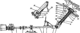
To establish synchronization of the engine and fuel injection pump operating cycles, you need to understand that the pump drive connecting through the engine timing gears must be disconnected. The drive is connected by connecting the holes of the pump drive gear 4 with the adjusting holes of a special washer 5 along the perimeter through a splined bushing fixed to the pump shaft. Access to the drive is achieved by opening the front cover 8 of the pump. To disconnect, unscrew two fastening bolts 3 with strip 7 and remove the adjusting washer from the splined sleeve. In this position, the rotation of the shaft cranks will not be transmitted through the camshaft gear drive to the pump shaft 6.
Injection pump drive device D 240
Momentoscope installation
After identifying the cylinder in the “compression” stroke and disconnecting the drive on the fuel pump, install a torque scope on the corresponding supply section of the pump instead of the high pressure pipeline connecting the section to the cylinder injector. To more accurately determine the beginning of the injection moment, set the manual fuel supply lever to the maximum position. To determine the moment of injection, if necessary, pump the fuel equipment with a manual pump pump, removing air from the system.
Injection installation operations
Determining and setting the timing of fuel supply
By turning the injection pump camshaft clockwise and observing the fuel level in the device tube, you need to determine the position of the pump shaft at the moment fuel supply begins in this section. The moment the supply begins will be the position at which the fuel level in the device tube begins to rise, shifting as a result of the start of the supply cycle, running the injection pump shaft cam onto the plunger pusher of the corresponding section
It is very important to determine, by observing the fuel level in the momentoscope, the beginning of this cycle
Setting the position of the pump drive shim
Having determined the moment of the start of injection on the section by the position of the injection pump shaft, connect the pump drive by installing a splined adjusting washer on the splined bushing. The fastening bolts with the strip are screwed into the most aligned holes of the washer and the flange of the pump drive gear. In this case, the bolts should fit freely without snagging. Then install the pump cover by tightening the three bolts around the perimeter of the cover. The axial clearance of the drive gear is adjusted using the adjusting central screw in the cover. To do this, unscrew the lock nut of the screw, screw it all the way into the washer bar and unscrew it 1/3 or 1/2 turn, after which the position is fixed with a lock nut.
Installing the cylinder head
Install the cylinder head on the engine in the reverse order of removal. Before installing the head, pour 30 g of GOST 8581-78 diesel oil into the cylinders. Lubricate new cylinder head gaskets, caps and cylinder head covers on both sides with graphite paste consisting of 40% graphite powder and 60% diesel oil.
Tighten the nuts of the studs or bolts of the cylinder head in several stages (no more than 1...2 edges) in the sequence shown in Fig. 2.4. Perform final tightening with a torque wrench. The final tightening torque of the nuts is 19...21 kgf•m (190...210 N•m) for D-243 and 16...18 kgf•m (160...180 N•m) for D-240.
Install injectors of the same throughput group. Lubricate the injector gaskets on the contact side with solid oil US-2 GOST 1033-73.
The tips of the push rods should fit into the recess of the pushers. The rods should rotate easily about their axes. Lubricate the gaskets of the thermostat housing and the intake tract with “Sealant” varnish. Adjust the gaps between the ends of the valves and the rocker arms.
READ ALSO ON THE SITE
Place the CI device on the valve spring plate and use the release cam to move the plate to the upper position. Any subsequent disassembly of the cylinders involves similar actions.
The main thing is that you need to follow all the methods given in the literature and make adjustments strictly following it. Before testing the piston group, check the parameters of the piston pin, connecting rod and the condition of the bushing of the upper head of the connecting rod.
Before installing the cylinder head on the block, you need to check and, if necessary, clean the mating surfaces of the head and block using a wire brush or scraper from burnt-on remnants of the old gasket, then wipe the surfaces clean with a napkin. Vibration, constant movement, temperature changes.
The rocker arm rotates on the shaft and the other end presses the valve, lowering it down.
The shock absorber is made in the form of a rubber cushion with a pair of vulcanized plates, with the help of which it is attached to the distribution cover bracket and the front support.
The walls of the cylinder block are made in the form of arches, supported by inter-cylinder partitions. Installing the piston ring 1 - piston; 2 - device; 3 - piston ring Fig.
If the engine performance deteriorates or smoke appears, you should not hesitate to check the valves! Adjustment data when assembling a diesel engine D Final tightening torque of the cylinder head nuts, Nm - Tightening torque of the connecting rod bearings, Nm - Gap between the valve stem and the rocker striker Thermal clearance on a cold diesel engine, mm 0.25-0.30 Piston at when at TDC, it should not protrude above the surface of the block by more than 0.5 mm. Installation of the MMZ D245 35 E4 block head part 1 (installation and tightening of the head)
We recommend: DIY rotary blade at MTZ
Cylinder head troubleshooting
Disassembly. Compress the valve springs using the OR-9913 tool (see Fig. 4). Remove the crackers, spring plates, outer and inner valve springs, and washers. Remove the intake and exhaust valves. Risks, scuffs and holes on the surface of the cylinder head valve seats are not allowed. If these defects are present, process the chamfers of the seats with cutters with guide shanks in the following order: - process the working surface of the intake and exhaust valve seats at an angle of 45°; - chamfer the bottom of the valve seats at an angle of 75°; - chamfer the top of the valve seats at an angle of 15°.
Rice. 4. Removing and installing valve springs using the OR-9913 tool.
If the width of the valve seat chamfer increases by more than 2 mm, reduce it with cutters with angles of 15 and 75°. The chamfer width of the valve seat after processing should be 1.5...2 mm; in this case, it is necessary to check the alignment of the chamfers with the guide bushings using the device KI-4929. Replace the valves in which deformation of the rod is detected. Check the height of the cylindrical flange of the valve disc, which should be at least 0.5 mm. If you find scratches and cavities on the working facet of the valve, as well as if the chamfer is worn, grind the working surface on the R-108 stand. Grind the chamfer of the intake and exhaust valves at an angle of 45° relative to the axis of the rod.
Check the elasticity of the springs on the KI-040A device (see Fig. 5). The values of compression force and spring height must correspond to the data in table. 1.
Rice. 5. Checking the elasticity of the valve springs on the device.
Table 1: Checking the elasticity of valve springs.
| Spring | Strengthening compression to working height, kgf | |
| normal | acceptable | |
| Outdoor | 17±1,4 | 14,8 |
| Internal | 8,87±0,7 | 7,4 |
| Spring | Height, mm | |
| in a free state | in working order | |
| Outdoor | 64,0 | 54,0 |
| Internal | 58,5 | 48,5 |
Replace springs that do not meet these requirements. Measure the inner diameter of the guide bushings using an indicator bore gauge (see Fig. 6). If the inside diameter is greater than 11.13 mm or there is a loose fit, replace the bushing (see Figure 7). Press in the new bushing with an interference fit of 0.03 mm (see Fig. 8).
Rice. 6. Measuring the valve guide hole.
Rice. 7. Pressing out the valve guide. Mandrel for pressing out.
Rice. 8. Pressing in the guide bushing.
After repairing the valves and their seats, grind the valves to the seats using a pneumatic drill 2213 (see Fig. 9). Lubricate the working surface of the valve chamfer with lapping paste (M20 micropowder with industrial oil 20 or spindle oil 3). Place a process spring on the valve stem, install the valve in the guide sleeve and rotate it, periodically lifting the drill. The width of the ground matte strip on the conical surface of the valve and valve seat should be 1.5...2 mm (see Fig. 10). The upper edge of the matte strip on the valve must be located at a distance of at least 0.5 mm from the cylindrical belt of the valve disc.
Rice. 9. Grinding in valves using a pneumatic drill.
Rice. 10. Matte strip on the valve chamfer.
Checking and adjusting the setting angle of fuel injection advance on a diesel engine
Maintenance » Checking and adjusting the setting angle of fuel injection advance on a diesel engine In case of difficulty starting a diesel engine, smoky exhaust, as well as when replacing or installing a fuel pump after checking at the stand every 120 thousand km or repairing a diesel engine, be sure to check the setting angle of fuel injection advance to diesel.
The values for the setting angle of fuel injection advance are given in Table 13. Table 13
| High pressure fuel pump | Diesel | |
| D-245.7E2 | D-245.9E2 | D-245.30E2 |
| Installation fuel injection advance angle, degrees of crankshaft rotation | ||
| 773.1111005-20.05 | 2,5±0,5 | |
| 773.1111005-20.06 | 3,0±0,5 | |
| 773.1111005-20.07 | 4,0±0,5 |
Figure 24. Sketch of the control device
- compression nut
- high pressure tube
Check the setting angle of fuel injection advance with fuel pumps, 773 (JSC YaZDA) in the following sequence:
- set the piston of the first cylinder on the compression stroke 40–50° before TDC;
- set the regulator control lever to the position corresponding to the maximum fuel supply;
- disconnect the high-pressure pipe from the fitting of the first section of the pump and instead connect a control device, which is a piece of high-pressure pipe 100...120 mm long with a pressure nut at one end and the other end bent to the side by 150...170° in accordance with Figure 24 ;
- fill the fuel pump with fuel, remove air from the low-pressure system and create excess pressure with a manual priming pump until a continuous stream of fuel appears from the control device tube;
- Slowly rotating the diesel crankshaft clockwise and maintaining excess pressure in the pump head (with a bleeder pump), monitor the flow of fuel from the control device. At the moment the fuel flow stops (up to 1 drop per 10 seconds is allowed), stop rotating the crankshaft;
- Unscrew the retainer from the threaded hole in the rear sheet in accordance with Figure 25 and insert it with the reverse side into the same hole until it stops in the flywheel, while the retainer must coincide with the hole in the flywheel (this means that the piston of the first cylinder is installed in a position corresponding to the installation angle fuel injection timing indicated in table 13).
Figure 25. Installing the retainer into the hole in the backsheet and flywheel
If the latch does not match the hole in the flywheel, make an adjustment by doing the following:
- remove the hatch cover in accordance with Figure 26;
- align the lock with the hole in the flywheel by turning the crankshaft in one direction or the other;
- loosen the nuts securing the fuel pump drive gear by 1...1.5 turns;
- Using a wrench, turn the fuel pump shaft counterclockwise by the nut until the pins stop against the edge of the groove of the fuel pump drive gear;
- create excess pressure in the fuel pump head until a continuous stream of fuel appears from the control device tube;
- by turning the pump shaft clockwise and maintaining excess pressure, monitor the flow of fuel from the control device;
- when the fuel flow stops, stop rotating the shaft and fix it by tightening the nuts securing the drive coupling half to the drive gear.
Recheck the timing of the start of fuel supply.
Disconnect the control device and reinstall the high pressure pipe and manhole cover. Screw the fastener into the hole in the back sheet.
Fuel pump drive
Figure 26. Fuel pump drive
Assembly
Assemble the cylinder head in the reverse order of disassembly. Before assembly, blow off the cylinder head and valves with compressed air. Wipe the valve plates and seats with a cloth soaked in kerosene. Install the valves in the seats to which they were ground. Lubricate the valve stems with diesel oil before assembly. The rods should move in the guide bushings without jamming or noticeable lateral wobble. The valve cotters should protrude 1±0.5 mm above the plane of the valve spring plate. Drowning up to 1 mm is allowed.
Cylinder block and valves of the D-243 engine
Cylinder block and valves of the D-243 engine
Cylinder head D-243
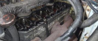
The cylinder head of the D-243 engine of the MTZ-82 tractor is a cast iron casting, in the internal cavities of which there are inlet and outlet channels closed by valves. To ensure heat removal, the cylinder head has internal cavities in which coolant circulates. On top of the cylinder head are mounted struts, a rocker arm axle with rocker arms, a head cover, an intake manifold and a cover cap that covers the valve mechanism.
On the fuel pump side, four injectors are installed in the head of the MTZ-82 engine block, and on the generator side, an exhaust manifold is attached to the head. To seal the connector between the head and the cylinder block, a gasket made of asbestos or non-asbestos sheet reinforced with perforated steel sheet is installed. The holes for the cylinder liners and the oil channel are edged with steel shells.
Checking the tightness of the bolts securing the D-243 cylinder head
Check the tightening of the mounting bolts for the D-243 cylinder head of the MTZ-82 tractor at the end of the run-in and after 1000 hours of operation on a warm diesel engine in the following order:
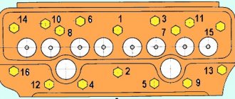
- remove the cap and cylinder head cover; - remove the rocker arm axle with rocker arms and struts; - using a torque wrench, check the tightness of all cylinder head mounting bolts in the sequence shown in Figure 19, and, if necessary, tighten them. Tightening torque -200±10 Nm.
After checking the tightness of the cylinder head bolts of the MTZ-82 engine, reinstall the rocker arm axle and adjust the gap between the valves and rocker arms.
Diagram of the sequence of tightening the cylinder head bolts of the D-243 engine
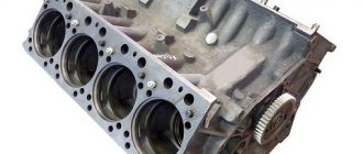
D-243 engine cylinder block
The D-243 cylinder block is the main body part of a diesel engine and is a rigid cast iron casting. Four removable sleeves made of special cast iron are installed in the vertical bores of the block.
The liner is installed in the cylinder block of the MTZ-82 engine along two centering belts: upper and lower. In the upper belt the liner is secured with a collar, in the lower belt it is sealed with two rubber rings placed in the grooves of the cylinder block. The sleeves are sorted into three size groups according to their internal diameter: large (B), medium (C) and small (M). The group marking is applied to the lead-in cone of the cartridge case.
It is necessary to install sleeves of the D-243 block of the same size group. Coolant circulates between the walls of the cylinder block and the liners. The end walls and transverse partitions of the cylinder block have bosses designed to form supports for the crankshaft. Covers are installed on these tides. The bosses together with the covers form beds for the main bearings. The beds for the main bearing shells are bored out from one installation complete with the main bearing caps. Changing covers is not allowed.
The D-243 cylinder block has a longitudinal channel, from which oil flows through transverse channels to the main bearings of the crankshaft and camshaft bearings. On the outer surfaces of the cylinder block there are machined mating surfaces for attaching a centrifugal oil filter, water pump, coarse and fine fuel filters, and oil filler neck.
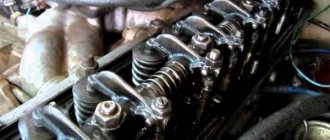
Timing timing mechanism D-243
The gas distribution mechanism of the D-243 engine of the MTZ-82 tractor consists of a camshaft, intake and exhaust valves, as well as parts for their installation and drive: pushers, rods, rocker arms, adjusting screws with nuts, plates with crackers, springs, struts and rocker arm axles.
The D-243 camshaft is three-bearing, driven from the crankshaft through the distribution gear. The camshaft bearings are three bushings pressed into the block bores. The front bushing (from the fan side) is made of aluminum alloy, has a thrust collar that holds the camshaft from axial movement, the remaining bushings are cast iron.
The pushers of the D-243 engine are steel. The working surface of the pusher plate is overlaid with bleached cast iron and has a spherical surface of large radius (750 mm). As a result of the fact that the camshaft cams are made with a small cone, the tappets perform a rotational movement during operation.
The push rods are made of steel rod. The spherical part that goes inside the pusher and the rod cup are hardened. The rocker arms of the MTZ-82 engine valves are made of steel and swing on an axis mounted on four racks. The outer pillars are of increased rigidity. The rocker axis is hollow and has eight radial holes for lubrication of the rocker arms. The movement of the rocker arms along the axis is limited by spacer springs.
Loose tightening force.
The tightening of the cylinder head bolts d 240 on MTZ 80-MTZ-82 tractors is carried out after installing the cylinder head or periodic tightening. It is necessary to periodically pull the cylinder head every 1000 m/hours of tractor running. During operation, constant thermal expansion of engine parts occurs. They are subject to emerging loads. This leads to loosening of the cylinder head.
- The head gasket is compressed
- The seats of the mounting bolt heads are sagging.
- The mounting bolts are stretched.
As a result, the pressure of the cylinder head to the cylinder block is weakened. And as a result, a breakthrough of exhaust gases from the combustion chamber occurs. Gases have a high temperature, it can reach above 1000 degrees. The gasket burns out in places where gases break through. As a result, you have to remove the cylinder head to replace the gasket.
How to tighten cylinder head bolts without a torque wrench
What is the procedure for tightening the cylinder head bolts?
The price of a professional instrument with acceptable accuracy reaches $200, which is beyond the means of the average person. However, physics gives users the right to independently manufacture a “likeness” of this instrument for a reasonable fee. To do this you will need:
- standard key;
- lever (pipe or other object);
- tape measure or ruler;
- standard scales (canter).
To tighten bolts without a torque wrench, you need to remember a little physics. The tightening torque is the applied force to the meter lever (kgf.m). Therefore, you need to measure the length of the key and divide 1 by the resulting number. Next, the result is multiplied by the tightening torque and the answer will be the required indicator on the scales.
- nut with a required force of 3 kgf*m;
- open-end wrench 25 cm long;
- scales with an indicator of up to 20 kg.
Total:
- 1/0,25=4;
- 4*3 = 12.
Thus, if you attach a scale to the key, you need to pull the hook with a force of 12 kg. If it is necessary to tighten a bolt marked in Newtons, the force is calculated using the standard ratio here too.
Installation of cylinder head gasket d 240
Before installing the gasket, the surfaces of the cylinder head and block must be thoroughly cleaned. From dirt and possible remnants of the old gasket. It is better to clean surfaces with a knife. It will not damage the surface. This cannot be done with sandpaper, much less with petal circles. After their use, the surfaces will become unusable. They will need to be milled. Even minor depressions will lead to gas breakthrough. And they are very easy to make with sandpaper and even a metal brush on an angle grinder.
In this case, if a turbine is installed on the engine. It is necessary to install fluoroplastic rings.
The turbine creates increased pressure in the combustion chamber. As a result, the temperature of the compressed air and its quantity increase. The combustion temperature of the fuel in the combustion chamber also increases. PTFE rings can withstand elevated temperatures. And protect the metal parts of the gasket from burning.
They are installed very simply. The outer edges of the rings have a recess. It needs to be expanded. You will get a groove. This groove is installed in the gasket in a circle. The excess end of the ring is cut off.
Operating principle of the ignition system
The ignition system is used for reliable and timely ignition of the combustible mixture entering the cylinder. It consists of a magneto, a spark plug and a high voltage wire.
The operating principle of this element is quite simple and reliable at the same time - when the working mixture enters the cylinder of the starting engine, it is ignited by means of an electric charge formed between two electrodes on the spark plug. For the highest quality charge, a fairly high voltage is required, approximately 10-15 kV, which is created in a special device - a magneto, which combines a number of functions - a breaker, an alternating current generator and a transformer.
Installing the block head
Before installation you must:
- Carefully inspect the surfaces of the head.
- Check the flatness of the head. Check the flatness of the head using a ruler. If there are loose fits, measure their depth with a dipstick. Simply put, a 0.1 mm thick probe should not pass between the ruler and the surface of the head.
- Inspect the seats of the mounting bolt heads. For the presence of cracks. And if they are found, these places should be milled. To prevent cracks from continuing to grow. The surface removed during milling should be compensated with larger washers.
- If the heads are removed, the valves must be removed. To change the oil of the reflective caps, grind the valves. And inspect the seats and between the valve partitions for cracks
If everything is in order, the head is installed on the gasket. Mounting bolts are inserted.
Replacing main and connecting rod bearings
If the engine is stopped due to low oil pressure in the line, first check the condition of the valves and rotor of the centrifugal oil filter, oil pump, oil pump outlet pipe and pipe flange gaskets.
Only after making sure that these components are in good condition, proceed to checking the condition of the main and connecting rod bearings.
The gap between the newly installed liners and the crankshaft journals is 0.065-0.123 mm. for connecting rod journals and 0.070-0.134 mm. for main ones when measured in a plane perpendicular to the plane of the bearing separation.
Replace the connecting rod and main bearings if the gaps between the bearings and the crankshaft journals with parts missing reach the following values:
- for connecting rod bearings 0.40 mm. with ovality more than 0.06 mm.
- for main bearings 0.40 mm. with ovality more than 0.1 mm.
- If, as a result of measurements, it is determined that the clearance in the bearings and the ovality of the crankshaft journals exceed the permissible limits, then grind the crankshaft journals to the next repair size according to the table below.
Crankshaft journal dimensions
When replacing bearings, install them of the same rating as the crankshaft journals.
Crankshafts, the connecting rods or main journals of which are made to the second nominal size on the first cheek, have additional designations:
- “2K” - main journals of the second denomination.
- “2Ш” - crankpins of the second rating.
- “2KSh” - connecting rod and main journals of the second rating.
When selecting liners, also pay attention to the designation of the size group of the liner by height. The sizes of the groups are indicated on the inner surface of the antennae with a “+” or “-“ sign. The kit includes earbuds: one with a “+” marking, the other with a “-” marking, or both without markings.
Cylinder head tightening torque d 240
Tightening of the cylinder head d 240 is carried out in several stages
- It is necessary to tighten the mounting bolts until they come into contact with the surface of the head. At this stage, you do not need to apply much twisting force. It is enough to simply tighten all the bolts into place by hand. Because the head should sit in its place without distortion. It is imperative to check that nothing has gotten under the head. Cable, hoses, wires. Unscrewed brackets.
- It is necessary to pre-tighten the bolts with a tightening torque equal to half the required force. This is approximately 100 N*M . Tightening must be done using a torque wrench. This condition is considered mandatory. A torque wrench not only allows you to set the required tightening force. But perhaps its most important advantage is. The point is. That this force will be the same for all bolts. If the head is not pressed with the required force. It is more important that the bolts are tightened evenly. Tightening must be done strictly in order according to the tightening diagram
- The final tightening of the cylinder head d 240 is carried out with a force of 200 N*m . Strictly in tightening order
Working with a torque wrench
At the beginning of installation, set the torque wrench to the position called zero by mechanics. This position is the moment when the key readings are equal to the initial position of the bolt. Look carefully at the numbers at the moment you start fastening, remember, or better yet, write down.
With slow and careful movements, start turning the key and carefully monitor the indicators; if the torque remains in the same place, then the fastener has succumbed to tension. If the moment changes sharply, then it is necessary to achieve movement of the bolt. A sharp increase in torque indicates that the holder is not fully stretched. Then installation will have to be done after stabilization.
If, during tightening, the torque begins to decrease sharply, the fastener is deformed and replacement is inevitable.
Driving on country roads immediately after the highway has a detrimental effect on the engines of domestic cars. When driving, the car’s engine constantly heats up and cools down, which has a bad effect on the quality of the mount. The bolts become loose, which leads to breakdowns and oil leaks. Sudden temperature changes negatively affect the correct fastening of bolts. Be responsible when replacing this small but important car part.
Here is a table of torques that must not be exceeded when tightening.
| Thread | Bolt strength | ||
| 8.8 | 10.9 | 12.9 | |
| M6 | 10Nm | 13Nm | 16Nm |
| M8 | 25Nm | 33Nm | 40Nm |
| M10 | 50Nm | 66Nm | 80Nm |
| M12 | 85Nm | 110Nm | 140Nm |
| M14 | 130Nm | 180Nm | 210Nm |
| M16 | 200Nm | 280Nm | 330Nm |
| M18 | 280Nm | 380Nm | 460Nm |
| M20 | 400Nm | 540Nm | 650Nm |
| M22 | 530Nm | 740Nm | 880Nm |
| M24 | 670Nm | 940Nm | 1130Nm |
| M27 | 1000Nm | 1400Nm | 1650Nm |
| M30 | 1330Nm | 1800Nm | 2200Nm |
| M33 | 1780Nm | 2450Nm | 3000Nm |
| M36 | 2300Nm | 3200Nm | 3850Nm |
| M39 | 3000Nm | 4200Nm | 5050Nm |
| M42 | 3700Nm | 5200Nm | 6250Nm |