P
Checking and adjusting the gaps between the rocker arm striker and the valve stem is carried out on a warm and cold A-01M engine after 240 engine hours. To do this you should:
1) – clean from dust and remove the cylinder head caps;
2) – check the tightness of the nuts of the valve rocker arms;
3) – check the tightness of the nuts that secure the cylinder head to the block;
4) – turn on the decompressor mechanism and observe the valve rocker arms (sixth cylinder), while simultaneously rotating the crankshaft manually (slowly) clockwise until the valves overlap, in other words, when the exhaust valve in this cylinder has not yet closed, and the intake valve has just begun open;
6) – slowly turn the crankshaft, pressing the pin until it fits into the recess located on the flywheel. The piston of the first cylinder will then be at TDC. during the compression stroke;
7) – turn off the decompressor mechanism and use a feeler gauge to check the clearance of the exhaust and intake valves of the first cylinder. If the gap is adjusted correctly, then a 0.25 mm thick probe should enter the gap with light pressure, and a 0.3 mm thick probe should enter the gap with force;
– to adjust, you need to unscrew the lock nut of the adjusting screw and, while holding it with a wrench, screw or unscrew the adjusting screw with a screwdriver to the required clearance;
9) – upon completion of the adjustment, it is necessary to lock the adjusting screw with a lock nut, holding it with a screwdriver. After this, you need to check the gap again using a feeler gauge by rotating the pusher rod around the axis to make sure there is no jamming;
10) – upon completion of adjusting the valve clearance of the first cylinder, you should proceed to adjusting the decompressor mechanism in this cylinder. To do this, it is necessary to install the decompressor roller so that the axis of the adjusting screws is in a vertical position;
11) – use the unlocked adjusting screw to select the gaps between the rocker arm and the screw, the rocker arm and the valve, and then turn the screw (clockwise) one turn, and then lock the screw;
12) – after completing the adjustment of the decompressor mechanism in the first cylinder, remove the set screw and screw it (with its continuous part) into the hole in the flywheel housing;
13) – slowly turn the crankshaft one third of a revolution, which corresponds to the end of the compression stroke in the fifth cylinder. Adjust the gaps in the valves and the decompressor mechanism of this cylinder (similar to the above);
14) - further turning the shaft by one third of a turn will allow you to adjust the gaps in the valves and the decompressor mechanism of the third, sixth, second, and fourth cylinders.
72 73 74 75 76 77 78 79 ..
ADJUSTMENT OF VALVE AND DECOMPRESSION MECHANISMS OF DIESEL A-01, A-01M and A-41
In the valve mechanism, the gap between the end of the valve stem and the rocker arm is adjusted. This gap is necessary to ensure that the valve fits tightly into the seat in the cylinder head and compensates for thermal expansion of the valve drive mechanism parts during engine operation.
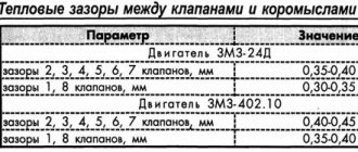
The gap A (see Fig. 14) between the stem of the intake and exhaust valves and the rocker arm is set to the same within
0.25-0.30 mm. With a larger gap, the valve timing shifts, the filling and cleaning of the cylinders worsens, shock loads and wear on the parts of the gas distribution mechanism increase, and even the valve stem may break. With a smaller gap, the valve does not fit tightly into the seat. As a result, the tightness of the combustion chamber is compromised, engine compression is reduced, it is difficult to start, the engine overheats and does not develop full power.
Incomplete closing of the valves leads to burnout of the working chamfers due to the breakthrough of hot gases.
Checking and adjusting the gap between the valve stem and the rocker arm
The gap is checked both on a cold and hot engine, but not earlier than 15 minutes after stopping it. They check in this order: turn off the fuel supply;
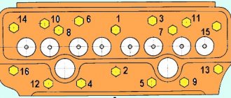
Clean the caps 7 (see Fig. 16) of the cylinder heads from aching. Unscrew the nuts 13 securing the caps, disconnect the lever for turning on the decompression mechanism and remove the caps;
Check the tightness of the nuts securing the struts 11 of the rocker arm axle and the nuts securing the cylinder head to the block;
Using a screwdriver or wrench, set the decompression mechanism to the on position to facilitate cranking of the crankshaft;
observing the rocker arms of the valves of the first cylinder, slowly rotate the crankshaft clockwise with the handle until both valves (exhaust and then intake) open and close, which corresponds to the initial period of the compression stroke. Unscrew the set screw from the hole in the flywheel housing and insert it with the unthreaded part into the same hole until it stops against the flywheel disk;
While pressing the set screw with your hand, continue to turn the crankshaft until the screw enters the recess on the flywheel disk; In this position of the crankshaft, the piston of the first cylinder is in. m.t. after the compression stroke;
Turn off the decompression mechanism and use a feeler gauge to check the gap between the rod and the rocker arm of the intake and exhaust valves of the first cylinder.
If necessary, adjust the gap.
To adjust the gap you need to:
Loosen lock nut 12 (see Fig. 14) of adjusting screw 1.3 on the valve rocker arm, holding the adjusting screw with a screwdriver;
Insert a 0.25 mm thick feeler plate into the gap and, turning the adjusting screw with a screwdriver, set the required gap;
Hold the screw with a screwdriver, tighten the locknut and check the amount of clearance by turning the push rod by hand to make sure it does not bind. With a correctly adjusted gap, a feeler gauge with a thickness of 0.25 mm should enter with light pressure, and a feeler gauge with a thickness of 0.30 mm should enter with force.
Adjusting the decompression mechanism
After adjusting the valve clearance of the first cylinder, adjust the decompression mechanism in this cylinder in the following order:
The decompression mechanism is turned on, the roller 8 is installed so that the axis of the adjusting screws 7 is vertical; loosen the locknut of the adjusting screw; Using the unlocked adjusting screw, select the gaps between it and the back of the rocker arm, the valve stem and the rocker striker;
Turn the adjusting screw one turn clockwise, and the valve will open slightly;
Hold the adjusting screw with a screwdriver and lock it with a nut.
After adjusting the decompression mechanism of the first cylinder, screw the set screw with the threaded part into the hole in the flywheel housing.
As the crankshaft is further cranked clockwise, the valve and decompression mechanisms in the next engine in order of operation are adjusted accordingly.
For A-01 engines and its modifications, the crankshaft is rotated through 120° (1/3 turn), for A-41 engines and its modifications - through 180° (1/2 turn), which will correspond to the end of the compression stroke in each subsequent cylinder (taking into account the order of operation of the cylinders).
Please note that the intake and exhaust valves must be closed before adjusting the clearances. In this position they are checked by turning the rods by hand.
After adjusting the valve and decompression mechanisms, start the engine; if valve knocking is heard, stop the engine and check the size of the gaps again.
Upon completion of the adjustment, install the cylinder head caps in place, observing the correct placement of gaskets 6 (see Fig. 16). Oil leakage in places where the caps are adjacent to the cylinder heads is not allowed.
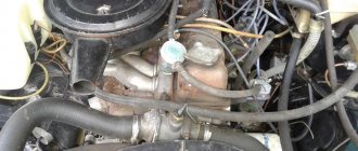
Domestic construction and agricultural machinery, special vehicles are equipped with various power units. One of their representatives is the A 41 diesel engine, produced by the Altai Motor Plant, located in Barnaul.
Specifications
A 41 is a series of four-cylinder naturally aspirated diesel engines. Their main purpose is use in construction equipment and agricultural machines. A 41 is a high-quality, unpretentious, durable unit, easy to operate and has good maintainability, and this characteristic of A 41 engines has allowed it to gain consumer recognition.
A41, removed from the DT-75 tractor:
Technical characteristics of the A 41 engine in the stock version:
- Engine weight A 41: 930 kg.
- Motor dimensions: length 1425 mm, width 827 mm.
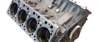
- Cylinder block design: cast iron BC.
- Fuel supply: direct diesel injection method.
- Cylinder operation algorithm: 1 – 3 – 4 – 2, counting is carried out from the engine fan.
- Volume: 7.43 liters.
- Developed power: up to 90 horsepower.
- Number of revolutions according to the passport: 1750 rpm. in a minute.
- Cylinders: 4.
- Cylinder arrangement: mounted vertically.
- Piston stroke length: 140 mm.
- Individual cylinder diameter: 130 mm.
- Standard compression ratio A41: 16.
- Developed: 412 Nm at 1300 rpm.
- Fuel consumption: min. 1.62 kWh.
- Cooling system of diesel engine A 41: liquid.
- Oil used: DS-11 in summer, DS-8 in winter.
- Motor generator: DC unit 7=G304, 214A1.
- Number of timing valves: 2
- Hydraulic pumps: 2 gear pumps, driven from the crankshaft by a gear-type transmission.
- Declared engine life: 12 thousand hours on the latest engine models.
How to install a clutch disc on an A 41 engine
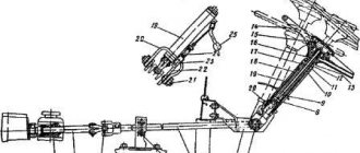
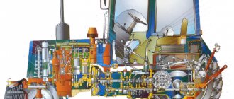
Diagram and principle of operation of the A-41 clutch (basket)
The DT-75 tractors are equipped with a double-disc single clutch, the type is permanently closed. Similar couplings are also used on the T-4 and T-74 tractor models. The clutch operates using the friction forces that arise between the driven, pressure and intermediate disks and the flywheel. The discs are located in the cylindrical internal cavity of the flywheel; The pressure and intermediate disks are connected to the flywheel through the drive pins. A special feature of the coupling design is the presence of a brake, which ensures a quick stop after the driven parts are turned off. Every 240 hours of operation of the unit, check the gap between the lift and the levers (2.5-3.5 mm), for which they set the control lever to the rear position, remove the cover and rotate the crankshaft, bringing the levers in turn to the hatch, take measurements, the difference which for different levers should not be higher than 0.3 mm. When adjusting the brake, the clutch is completely disengaged, the adjusting bolt (pos. 27 in the figure) is unscrewed to a position at which the hand can firmly press the block to the pulley. Then the bolt is tightened until it touches the spring stop and then an additional 2.5 turns are made, locking with a lock nut.
If necessary, on the A-41 A52.22.000-10 clutch basket, adjust the locking mechanism by changing the length of the rod that connects the end of the lever (lower) and the roller lever in the gearbox locking mechanism. In this case, the clutch lever is placed until its short arm touches the stop, to which it is pressed by a spring. The clutch control lever (lower end) and the roller lever are connected until the upper control lever is deflected from the vertical by 12-15 degrees. The roller lever is turned all the way into the cover boss and connected to the lower end of the clutch control lever, while adjusting the rod length.
Adjusting the clutch pedal free play
When the tractor is operating, due to wear of the friction linings, the free play of the clutch pedal gradually decreases, which should be checked every 125 hours of operation. The stroke of lever 5 at the radius of pin 6 should be 6.7 mm, which corresponds to a free stroke of 40.50 mm of the clutch pedal 1. Adjust the clutch control in the following sequence:
- disconnect rod 8 from lever 5 by removing pin 6;
- unscrewing adjusting bolt 2, return pedal 1 to its original position until it stops against the floor;
- turn lever 5 counterclockwise until the release bearing stops in the release levers and, rotating the fork 7 of the rod 8, align the holes of the lever and the fork, then shorten the rod 8 by about 5 turns of the fork 7 and connect it to the lever with a finger; check the free play on the clutch pedal pad;
- check that the clutch pedal returns to its original position when it is retracted to its full travel. If the pedal gets stuck, you must loosen the bolts 4 and turn the bracket 3 clockwise or tighten the adjusting bolt 2 to an amount that ensures the pedal returns to its original position. If the free play of the clutch pedal cannot be adjusted by changing the length of rod 8, and the stroke of lever 5 when measured at the radius of pin 6 is less than 4 mm, adjust the position of the release levers as indicated below.
Review and features - A-41 engine
The 90-horsepower engine has a respectable cylinder capacity of 7.43 liters, which allows the base model A 41 to produce such power at relatively low speeds, about 1750. Following engine development trends, the developers introduced an electronic direct injection system into the A 41: fuel supply is completely controlled electronically.
An important feature of the A 41 engine is its two-valve gas distribution mechanism. Engineers used it to give the engine the highest possible efficiency, output and efficiency.
To make the unit more reliable, the A 41 uses high-strength cast iron liners, the surface of which is treated by top honing. This increases the life of the motor, coupled with a well-thought-out cooling system (although the weight also increases). As such, an external oil-liquid heat exchanger is used, which cools the engine equally well both in idle mode and at maximum loads. By maintaining a stable, comfortable operating temperature, engine reliability has been further improved.
An interesting feature of the engine: during engine operation, the valves are able to rotate under the influence of their own springs and vibrations accompanying the engine operating cycles. This can be attributed to the advantages of the design, since the valve stem wears more evenly (although the chamfer of the valve plate also wears out).
The engine camshaft must withstand heavy loads, so it is hardened with high-frequency currents. The camshaft has 7 journals and 12 cams that ensure the operation of the mechanism. The unit is driven by the crankshaft through a gear transmission.
The developers also took care of the environmental friendliness of the power unit: the engine released from the AMZ workshops complies with the domestic standard R 41.96-2005 for the absence of violations in the emission of pollutants and harmful substances.
We insert the ignition on the ZIL-130 diesel
It is difficult to turn on the ignition on ZIL-130 cars from the 80-90s with an old cabin. To set it we need to unscrew and remove everything that will interfere with us so that we can see the ignition ridge. On my car, as shown in the video, you need to remove the compressor, remove the compressor plate and only then can you get to it.
To get there, remove the ignition cover; it has 3 bolts. We unscrew the hazel grouse with 2 bolts. We take out the bolts and look at the hazel grouse; there should be 2 marks + and - on it. To the side where + if we move it by 1 hole we will make early ignition, if - then later. There is just a mark on some hazel grouse without + and -.
Ignition installation MTZ-82
Here we look from the front of the car to the engine; if we move it clockwise, it will be earlier, if counterclockwise, it will be later. You will immediately understand by the operation of the engine. The only negative, and a very big one, is that it’s inconvenient to do everything and you have to crawl up to the ignition hazel grouse with your head down to death and somehow dodge it.
WATCH THE VIDEO
Motor modifications
The engine is available in various variations designed to work with certain special equipment.
Main models:
The basic engine model and modifications are installed on tractors and other equipment, in agreement with the manufacturer. In total, there are more than 11 engine variations, differing mainly in additional equipment. You can put:
- two hydraulic pumps;
- upgraded clutch block coupling;
- muffler;
- pneumatic compressor;
- pre-start electric torch heater;
- enlarged heat exchanger of the engine oil cooling system, etc.
Engine modifications A-41SI1, 02 and 03 differ from each other in the arrangement of the cylinders: the latter received an in-line layout, due to which the nominal power developed by the engine increased to 100 forces, and the torque reserve - up to 20%, compared to its counterparts. According to the plant catalogue, popular tractors of the DT-75 series are equipped with A 41I, SI, S engines.
Since 2001, engines have been assembled with their own heads for individual cylinder groups, which has improved the reliability of the gas joint and reduced engine oil consumption “waste.” In 2003, a modification was created with electric start, which increased the service life. And in 2012, the crankcase block of the A 41 engine was replaced with licensed German crankcases, which made the engine even more reliable.
Block crankcase:
The A-41 has a related engine, the A-01, also designed to operate on special equipment. Unlike the A-41, the second engine has 6 cylinders.
Maintenance
As already mentioned, the A 41 and its modifications are unpretentious in terms of operating conditions and service. A qualified technician can easily handle routine maintenance tasks on his own.
In fact, for long and uninterrupted operation of the engine, it is necessary, mainly, to monitor the oil temperature and pressure in the oil line, not allowing the lubricant level to fall below a critical level, and flush. Oil changes are carried out regularly, every 240 engine hours.
An important regular operation is clutch adjustment, since with gradual wear of the disc linings, the outlet clearances of the middle disc and the free play of the clutch increase. Schematic design of the clutch using the example of that in the DT-75 tractor:
This is a dry double-disc clutch of a permanently closed type. Adjustment of the DT 75 clutch with the A 41 engine should be carried out, if necessary, based on the test result, approximately every 240 operating hours.
Over time, it may also be necessary to adjust the valves of the A 41 engine. A gap of 0.25 ... 0.3 mm is allowed for both valves of this engine.
The motor should also be serviced every shift, at the end of the shift or before the start. The current service interval is about 10 engine hours. The set of manipulations includes:
- cleaning the engine from dirt and accumulated dust;
- checking fastenings and tightness of joints;
- control of the absence of extraneous noise;
- checking for fuel, water and engine oil leaks.
- The engine cooling system should also be regularly maintained. The set of service operations includes:
- descaling from the cooling unit, flushing the system;
- checking for leaks and sealing weak points of the radiator, if necessary.
Check the tightness of the nuts (valve rocker arms and cylinder head to block) to ensure correct valve clearances.
Turn on the decompression mechanism and slowly rotate the engine crankshaft until the intake and exhaust valves of the first cylinder are completely closed (both valve rocker arms should swing freely by the amount of the gap between the strikers and the valve stems).
Remove the set screw from the flywheel housing and insert it into the same hole with the unthreaded part. Then, pressing the screw, turn the engine crankshaft until the set screw fits into the recess on the flywheel. In this case, the piston of the first cylinder is set to position c. m.t. compression stroke.
Turn off the decompression mechanism and check the gaps between the rocker arms and the valve stems with a feeler gauge.
It should be borne in mind that checking and adjusting valve clearances with the decompression mechanism turned on will lead to incorrect results that interfere with the normal operation of the valve mechanism. With correctly adjusted valves, the clearances (on a cold engine) should be in the range of 0.25-0.30 mm.
If the valve clearances do not correspond to the specified value, they are adjusted. To do this, loosen the lock nut of the adjusting screw, holding it with a screwdriver. Then, holding the locknut with a wrench, unscrew the adjusting screw and install a 0.3 mm thick feeler gauge between the rocker arm striker and the valve stem. The adjusting screw is tightened so that the probe moves with force. After this, holding the adjusting screw with a screwdriver, tighten its locknut. Check the gap again using the feeler gauge by rotating the pusher rods (to make sure that the rod does not touch the walls of the block).
Screw the set screw into the threaded hole in the flywheel housing. Turn the engine crankshaft half a turn, setting the piston in the third cylinder to the position corresponding to the end of the compression stroke. Adjust the valve clearances of the third cylinder. When you further turn the crankshaft half a turn, adjust the clearances in the fourth cylinder, and then in the second.
After adjusting the valves, be sure to adjust the decompression mechanism. To do this, install the decompression mechanism roller so that the adjusting screws are located vertically (with the stop tails facing the valve rocker arms); unlock the adjusting screws; tighten the adjusting screws, selecting the gaps - between the screws and rocker arms, valves and rocker arms; Unscrew each adjusting screw one turn and lock them.
Having finished adjusting the decompression mechanism, install the cylinder head cap in place, correctly positioning the sealing gasket, and secure the cap. The operation is completed. You can check the valve adjustment by starting the engine.
Typical faults
The motor has some characteristic problems.
- Overheat.
The engine cooling system uses mainly water as a coolant, which leaves calcium deposits on the radiator honeycombs and sediment in the pipes and cavities of the system. Therefore, you should regularly check the condition of the radiator and flush it, especially if the engine is expected to be operated under high loads. Sometimes, in advanced cases, it is necessary to change a failed pump or a thermostat on the A 41 engine that has stopped working.
- Abnormally high consumption of engine oil due to waste.
The reason for this is a leaky valve cover, which is specific to a separate cylinder group. It is to correct this shortcoming that the new models use German-made crankcase blocks.
- Loss of engine power, strong vibrations during engine operation.
The probable cause is a defect in the crankshaft assembly or pistons. You should also check the balancing bearings; they tend to break and then have to be replaced.
- Poor engine starting, interruptions in operation.
The reasons for this may be problems with the injection system or a fuel filter clogged with dirt. You should diagnose the fuel system, clean or replace the filter, and if this operation does not have an effect, open the engine and check the internal components.
Specifications
| OPTIONS | MEANING |
| Engine weight, kg | 930 |
| Dimensions (length/width), mm | 1425/827 |
| Cylinder block material | cast iron |
| Supply system | Direct injection |
| Engine operating order (counting from the fan side) | 1 — 3 — 4 — 2 |
| Cylinder displacement, l | 7.43 |
| Power, l. With. | 90 |
| Nominal speed, rpm. | 1750 |
| Number of cylinders | 4 |
| Cylinder arrangement | vertical |
| Piston stroke, mm | 140 |
| Cylinder diameter, mm | 130 |
| Compression ratio | 16 |
| Maximum torque at 1200 - 1300 rpm, Nm | 412 |
| Fuel | diesel |
| Minimum specific fuel consumption, kWh | 1.62 |
| Cooling system | Liquid, with forced circulation of coolant |
| Oil | In summer, diesel oil DS-11 (M12V) or M10V; in winter - DS-8 (M8V). |
| Generator | DC 214A1 or G304. |
| Hydraulic pumps | 2 gear type pumps NSh10DL and NSh46UL; driven by a gear transmission from the crankshaft. |
The engine is installed on tractors DT-75M, T-4A, T-4, excavators, rollers, motor graders, pumping units, power plants.
Description
The displacement of this four-cylinder diesel engine A 41 is 7.43 liters, which allows it to provide power of 90 horsepower at 1750 rpm. The A 41 engine has a direct injection system, which in the latest versions is fully electronically controlled.
A design feature of this power unit is a two-valve gas distribution mechanism, which ensures maximum efficiency and output. To increase the reliability of the design, the A 41 diesel engine used special liners made of cast iron with surface treatment using top honing technology.
The cooling system used can significantly reduce the operating temperature, which has a positive effect on the reliability of this power unit. An external liquid-oil heat exchanger is used to cool the oil, allowing the power unit to operate at maximum loads and under difficult operating conditions.
Main features, overview information
If the engine is 90-horsepower, then it will have a cylinder volume of 7.43 liters. Thanks to this, serious power appears even at relatively low speeds. The developers are trying to follow the latest trends characteristic of the motorcycle industry. Therefore, a direct injection system was built into the control system unit. This means that only electronic systems control the fuel supply.
Another important feature is the use of a gas distribution mechanism with two valves. Engineers used this part to give maximum efficiency to their engine. The output and efficiency of the device have also improved, which is proven by numerous photos; the A 41 engine gets better with each modification.
High-strength cast iron sleeves add to the overall reliability of the unit. Their surface is treated with a special method - vertex honing. The cooling system becomes more sophisticated, and the overall working life increases. But we must remember about weight gain. The main element of the cooling system is the oil-liquid heat exchanger. It cools the engine equally well both in idle mode and in the presence of additional loads. Engine stability has been greatly improved due to the fact that it is now able to maintain a stable, comfortable temperature. This helps the clutch of the A 41 engine work better.
What other parameters deserve attention?
Among the interesting parameters is that the valves rotate during engine operation when they are acted upon by their own springs. This is due to vibrations that accompany standard operating conditions. Valve engines are considered more reliable, so this design can be considered an advantage of the device.
The heaviest loads usually fall on the camshaft. Therefore, its hardening involves the use of high-frequency currents. The operation of the mechanism is ensured by 12 cams and 7 necks, which are located inside.
The unit begins to move when interacting with the crankshaft. Gear transmission takes part in this process.
The environmental friendliness of the power unit is another issue that the developers have seriously thought about. Units that have left production have no violations in the direction of emission of harmful substances into the atmosphere. Therefore, the lubrication system of the A 41 engine remains reliable.
Modifications
Over the years that this engine has been on the assembly line, it has undergone minor changes that have significantly simplified equipment maintenance, improved its reliability, reduced fuel consumption and increased power.
For example, modification A-41SI-03 has an in-line arrangement of cylinders, which made it possible to increase the rated power from 90 to 100 horsepower. This power unit has a torque reserve coefficient of 20%, while for modifications A-41SI-1 and A-41SI-02 this figure is 15%.
Since 2001, in the manufacture of these power units, individual cylinder heads have been used for each group of cylinders, which in turn has increased the reliability of the gas joint seal and reduced oil consumption during combustion.
The engine, while on the assembly line, was improved, receiving various electronic control units. In 2003, this power unit began to be equipped with an electric starter, which increased its service life. In 2012, under license for the A 41 diesel engine, German crankcase blocks began to be installed, which increased the reliability of the engine.
A total of 11 different modifications were produced, most of which are a basic engine with additional attachments installed on it. So, for example, it is possible to install two hydraulic pumps, a belt pneumatic compressor, an additional generator, an enlarged liquid-oil heat exchanger designed for oil cooling, a modernized clutch and a number of other elements.
A41 engine how to set the ignition
The first and main difference between a diesel unit and a gasoline unit is the ignition system or, in other words, how the fuel is ignited in the engine.
In an engine that uses diesel fuel, ignition occurs when diesel fuel comes into contact with air heated by compression, which accumulates inside the engine cylinder.
When they talk about adjusting the ignition system in a diesel engine, these words mean the process of changing the advance angle of the injection of fuel supplied at a specific moment - at the very end of air compression.
If the angle is set incorrectly and differs noticeably from the required parameters, then fuel injection will occur untimely, which will interfere with the normal operation of the engine and can cause the most dire consequences for further operation.
Also, an incorrectly set angle leads to incomplete combustion of fuel in the cylinders.
In other words, the ignition system in a diesel engine is one of the most important components. A special high-pressure pump, the injection pump, is responsible for supplying fuel to such an engine.
This device, together with the nozzles, determines the dosage of diesel fuel that is supplied to the engine.
Often the driver has to deal with the fact that he needs to set the ignition with his own hands, for example, if it is necessary to replace the timing belt.
In the second case, the need to adjust the system appears when the fuel pump is removed.
When disassembling fuel equipment, the first thing you need to do is remember all the marks. This can be easily done with a marker or paint. The main thing is to put the marks exactly where they are needed.
Thanks to this, assembling the ignition and fuel systems will be very simple, and it will also make it possible to avoid complications with starting the engine in the future.
The ignition system can be adjusted in different ways.
The first method is to set the angle exactly according to the indicated marks. The second method is to gradually select the correct position of the adjusting coupling.
Both methods will be discussed in this article.
If you set the angle yourself according to the marks, you will need to move the fuel supply pump. This method is more applicable to diesel engines with mechanical fuel supply equipment.
In order to adjust the injection advance, you need to smoothly rotate the drive coupling of the high-pressure pump around its axis.
There is another option - this is to rotate the camshaft pulley in relation to the hub. These adjustment options are suitable for structures that do not have rigid fastening of these parts.
So, when adjusting the ignition on the unit, the first thing you need to do is get to the rear of the engine, find the flywheel there and, if necessary, free it from the protective casing. After this, you need to find a stopper and install it in a special slot, but do not stop the flywheel yet.
When this is done, using a tool (wrench) you need to start turning the flywheel. When it rotates, the crankshaft will rotate along with it. You need to rotate until the flywheel stops.
After stopping it, you need to pay close attention to the pump shaft. If, after rotation, the scale on the drive coupling is in the top position, this means that the mark mounted on the fuel pump flange is aligned with the zero mark on the drive.
If the marks are aligned, you can safely tighten the fastening bolts.
However, if after all the procedures they diverge, then you need to lift the flywheel stopper again and continue turning the crankshaft, while monitoring the position of the scale on the drive.
If everything is done correctly, then after tightening the fastening bolts, the flywheel is released from the stopper and the crankshaft is turned 90°. After this, the stopper is again placed in the groove.
Now you can install the flywheel protection back and try to start the engine. If the motor starts working, you need to analyze how it does it. If everything was done without errors, the engine will run very smoothly without interruption.
With the second method of adjusting the ignition, the angle is set experimentally.
Let’s say that if the engine is not running, then the high-pressure pump pulley slowly begins to rotate by a certain number of teeth relative to the timing belt. After this operation, they try to start the engine again. If it works quietly, without knocking, then everything is fine.
If there is a clear knock, you can try turning the pulley some more. The appearance of smoke when starting the engine will mean that the late advance angle has been set.
Maintenance
Servicing this power unit is not particularly difficult, which allows you to carry out such work yourself.
- In fact, when operating equipment with this type of engine, you only need to constantly monitor the oil pressure and temperature, be sure to check the current lubricant level, wash the oil filter and promptly change the oil every 240 engine hours.
- Shift maintenance is carried out daily, at the beginning or end of the shift, every 8-10 operating hours. At the same time, the engine is cleaned of dust and dirt, fasteners and connections are checked for tightness, whether there are any extraneous noises, fuel is added (if there is any leakage), oil and water.
The engine cooling system of modification A 41 is serviced on a regular basis. The system must be flushed to remove scale, and if there is a leak, the radiator is additionally sealed.
Maintenance and repair
Maintenance of the A01 motor is quite simple. We can say that it is similar to all diesel power units, such as YaMZ. Maintenance is carried out every 12-15 thousand kilometers. This indicator includes changing the engine oil and filter element. It is also recommended to check the ignition and the condition of the air filter. Do not forget that the air element is replaced every second maintenance.
The engine is not particularly demanding in the use of fuel and engine oil. So, for normal operation any more or less high-quality mineral lubricant is suitable. As practice shows, motorists usually pour oil such as M10 into the engine. It perfectly performs all the necessary functions, and also, if replaced in a timely manner, protects the engine elements well. It is recommended to pay special attention to the air filter. It is best to take a quality product with a metal base.
Malfunctions
| FAULT | CAUSE |
| The engine overheats, which makes it impossible to operate the equipment. | The cooling system of this power unit uses mainly water, which can lead to sedimentation or the appearance of calcium deposits on the radiator honeycombs. That is why, when the operating temperature increases, it is necessary to inspect the condition of the radiators, rinse them, removing the corresponding scale. In some cases, it is necessary to replace the thermostat or replace a broken pump. |
| Increased oil loss is noted. | The reason for this may be a valve cover that has lost its seal, which is installed separately on each group of cylinders. A similar problem was solved in the latest modifications of this engine, where German crankcase blocks were used. |
| The A 41 engine has lost most of its power and is running with noticeable vibration. | It is necessary to open the power units and check the condition of the pistons and crankshaft. Quite often balancing bearings fail and require appropriate replacement. |
| There are interruptions in engine operation and problems with starting are noted. | The cause of such a breakdown may be a clogged fuel filter or problems with the injection system. It is necessary to first inspect the condition of the fuel system, and then open the engine. |
How to set the ignition on a diesel engine
How to set the ignition on a diesel engine?
The need to solve this problem may arise in one of the following cases: After the timing belt has been replaced.
After the high pressure fuel pump has been removed or replaced. After this, it may be impossible to find the marks where the pump pulley was installed. Therefore, before starting repairs, it is better to update the tags, so as not to suffer with the ignition later. You can do this in different ways, such as applying paint around the mark.
But if you still have a problem with setting the ignition, you can go in two ways.
How to set the ignition on a diesel engine. Method No. 1
The first way is to set the ignition using the trial and error method. It should be noted right away that this method is not optimal. Moreover, if the ignition is set for too long in this way, it does not add survivability to the engine and reduces its service life. But this method is still worth considering.
How it's done
• Once the pulley is installed, an attempt is made to start the engine. If the diesel engine does not start at all, the pump pulley rotates in relation to the belt by 3-5 teeth. An attempt is made again to start the engine.
• If the engine starts after several movements, you need to understand how a diesel engine works. If you hear a knock, you need to turn the pump pulley 1-2 teeth in the direction opposite to the rotation of the pulley.
• If there is a lot of smoke coming out of the exhaust pipe when the engine is running, this means that there is a delayed injection of diesel fuel. In this situation, the pump pulley must be turned one tooth forward in relation to the belt.
• If all these actions do not help, you will have to loosen the pump and by turning it around the axis, try to achieve normal operation of the diesel engine. Ideally, a diesel engine should operate on the edge of detonation levels. As soon as detonation begins, it becomes audible through the sound of the engine.
How to set the ignition on a diesel engine. Method No. 2
The second way of setting the ignition is more correct from a technical point of view.
How it's done
• The high pressure pipe from the injector of the 1st cylinder is removed.
• A transparent plastic tube is placed over the high-pressure tube (tubes are sold at any hardware store). The transparent tube should be vertical.
• The ignition is turned on and the pump pulley is rotated with the key. As you rotate, we determine the upper point of the fuel position in the tube, and accordingly in the nozzle. The pulley must be rotated very slowly and smoothly, without sudden jerks.
• Once the desired point is found, a mark is placed on the pulley.
• After this, the positions of the camshaft and crankshaft are set using the marks.
You can set the timing of diesel fuel injection even more accurately by moving the fuel pump. But if the pump was not removed before repair, then there is no point in touching it.
If all these steps seem too complicated, then it makes sense to contact an experienced mechanic or an appropriate service whose specialists know perfectly well how to set the ignition on a diesel engine.
But in order to eliminate the possibility of setting the ignition again, it is necessary to update the marks before any repairs related to removing the belt or injection pump.