Causes of breakdowns
Malfunctions and causes of breakdowns:
- The receivers are not filled with compressed air, which is why the pressure regulator is not activated. The cause of the breakdown may be a damaged hose or pipeline, loose tightening of the pipeline connection, poor tightening of the housing mechanisms, or a violation of the tightness of the receiver.
- When the receivers are full, the pressure level regulator is activated. The cause of the breakdown is a leak of compressed air flow from the compressor part into the main line to the safety valve block.
- The mechanism is not filled with compressed air. The malfunction may be caused by incorrect adjustment of the regulator or clogged pipelines.
- The faucet is leaking air. This may be caused by a malfunction of the energy storage unit.
- Increased blood pressure. The cause of the breakdown is a faulty two-pointer pressure gauge or faulty adjustment of the mechanism responsible for air pressure.
- The brake valve hisses. The malfunction may be due to damaged electrical equipment or a defective crane handbrake.
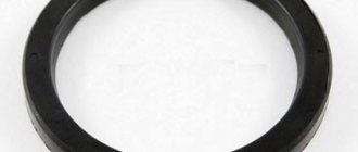
- Loss of tightness of O-rings. This means that there is an air leak in the system or the pusher mechanism has become stuck.
Two-piece brake valve
| Double safety valve. |
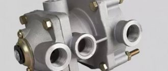
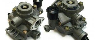
A two-section brake valve is designed to control the actuators of the vehicle's service brakes and drive the trailer brake control valves in the presence of a separate drive to the brakes of the front axle and the rear bogie.
A two-section brake valve (Fig. 5.11) is used to control the wheel brake mechanisms of the service brake system and the combined drive of the trailer brake mechanisms.
Caring for a two-section brake valve consists of periodic inspection, cleaning it of dirt, checking for leaks and operation.
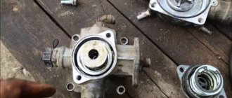
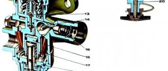
All buses under study are equipped with two-section brake valves with separate braking of the front and rear wheels. The brake valve consists of two parts. The upper valve / (Fig. 108) controls the rear brakes, and the lower valve 6 controls the front brakes. A pipeline from an air cylinder is connected to the head 4 of each valve. Cavity A to the right of the valve diaphragm communicates with the brake chambers. Cavity B to the left of diaphragm 7 is connected to the atmosphere.
Compressed air from the lower section of the two-section brake valve enters the outlet / / / of the pressure limitation valve and, acting on the end of the stepped piston 3, moves it along with the interconnected valves 4 and 6 down.
In the absence of braking, output / is connected to the atmosphere through a two-section brake valve.
When braking a car, compressed air from a two-section brake valve is supplied first to the brake control valve at -, a chain with a two-wire drive, and from it to the output / / / of the valve in question.
The functions of the spare brake system are performed by one of the circuits, since the presence of a two-section brake valve 4 and a double safety valve 9 allows both circuits to work independently of each other when the air pressure in any of them drops.
The automatic brake force regulator has three outputs: 1-to the upper section of the two-section brake valve; 11 - to the brake chambers of the rear wheels of the trolley; III - into the atmosphere.
When braking with the working brake mechanism (circuit II), compressed air from a two-section brake valve is supplied through a special fitting into the cavity of the chamber above the membrane (Fig. 221, d), which is connected through the rod I and fork 7 (Fig. 227, b), connected to the adjusting lever, activates the wheel brake mechanism.
Circuit I of the front brake drive consists of a 20 liter air cylinder, the upper section of a two-section brake valve, a pressure limiting valve and a control valve for the brake chambers and a control outlet. The air cylinder is equipped with a condensate drain valve, which allows you to remove condensate from the air cylinder, and a pressure drop sensor.
In the absence of braking (Fig. 241, b), no air is supplied to terminals / and / / / from the two-section brake valve.
Circuit II of the drive of the working brake mechanisms of the wheels of the rear bogie - under the action of the pedal, compressed air from the upper section of the two-section brake valve through the brake force regulator 30 (see Fig. 226) enters the brake chambers of the 27 wheels of the rear bogie, producing braking.
The valve has three outlets: / - into the atmosphere; II - to the brake chambers of the front wheels; / / / - to the lower section of the two-section brake valve for controlling the working brake mechanisms.
Main brake valve KAMAZ 5320: device
KamAZs, MAZs, ZILs are those cars that ordinary car enthusiasts have no interest in. But, despite this fact, they all have a rather interesting design, the nuances of which are better to know, especially if you have to get to know these giants better. In particular, special attention should be paid to the brake system, the design of which includes a brake valve (at the moment we are referring to the KamAZ vehicle, which will be discussed further).
Construction of a two-section brake valve
The KamAZ main two-section brake valve is designed to control the working brake systems of the vehicle and the combined drive of the trailer brake mechanisms, which is fully consistent with the design of the unit.
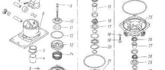
The main constituent elements include: a large piston, follower and small stage pistons, upper and lower valves, an elastic element, a pusher, a lever, a pin and a small piston pusher.
The first and second terminals of the valve are connected to the brake chambers of the front and rear wheels through intermediate pneumatic devices, while the third and fourth are connected to the receivers of separate circuits of the service brake drive.
Being in the initial position (with the brake pedal lowered), the valves are closed, the first terminal is disconnected from the fourth terminal, and the second terminal is disconnected from the third (“communication” with the atmosphere occurs through the valve).
When the driver of the vehicle begins to brake, the braking force applied to the pedal is transmitted to the stepped piston through the elastic element. Moving down, the piston closes the valve outlet, thereby cutting off the brake circuit outlet from the environment.
When the upper piston moves down, the already compressed air passes into the circuit of the working brake mechanisms of the rear wheels. The effect of compressed air, together with the spring action of the stepped upper piston, balances the force on the pedal.
Thus, the principle of operation of the KamAZ brake valve can be called a fairly simple and natural process.
Causes of crane breakdowns
Like any other vehicle, a KamAZ vehicle sometimes encounters operational problems, which are often caused by structural brakes, or rather by faults in the unit.
In particular, the main problems with a two-section crane include loss of tightness of the rubber sealing elements (pistons and rings) and, as a result, air leakage from the system, as well as sticking of the pusher, which makes it impossible to completely release the machine.
As for air leakage into the atmosphere , it can occur through the inlet window (which is mainly caused by defects in valves and springs) and through the housing connector (the result of a defective O-ring and damage to the end surfaces of the housing).
Lever jamming is often caused by contamination of the lever mechanism, resulting in damage to the protective cover.
Another fairly common malfunction of the brake system of a KamAZ vehicle is a slow increase in pressure in the lower section while it increases in the upper part. This problem is caused by swelling of the O-rings.
We should not forget about the possibility of disruption of the tracking action along the lever, which is caused by a defect in the elastic element.
How to check the Kamaz brake valve
The main valve of the brake system , which is a two-section type (in this case we mean KamAZ vehicles), is located on the left side member of the frame and is attached to it using a special bracket.
Diagnosis of this mechanism should become a regular activity
, since with periodic inspection, systematic cleaning of accumulated dirt and checking the tightness of all connections, you will be guaranteed
stable operation of the specified unit.
In particular, during a visual inspection, special attention should be paid to the condition of the crane's protective cover . This part must not have any breaks and must fit snugly around the entire perimeter of the brake valve body.
The tightness of the connections can be checked using a soap emulsion in two positions of the valve - braked and unbraked.
If bubbles appear on the applied composition, it means there is still an air leak. In the case when it exits through the atmospheric outlet of the valve we are interested in, we should check the tightness of the inlet valve and the functionality of the outlet valve.
If, as a result of diagnostics, such defects are found, then such a faucet must be replaced.
The brake valve drive also needs periodic inspection, cleaning and lubrication of the articulated joints.
When carrying out all diagnostic activities, do not forget about the brackets, rods and levers that connect the brake pedal to the brake valve. They should also be periodically cleaned of small foreign objects and dirt.
If
the brake pedal is loose, be sure to adjust its travel, which can be done using an adjusting fork, through which the length of the rod connecting the machine pedal to the first intermediate drive lever is set.
If for some reason the brake valve drive has already been disassembled before, then during assembly it is necessary to ensure complete alignment of the lower hole of the intermediate lever and the cab tilting axis. After this, changing the length of the rod that goes from the pedal to the front lever, you should set the pedal to the required position in the cabin.
Replacing the brake valve
Replacing the KamAZ main brake valve, an approximate operating diagram of which was given above, requires dividing time into two successive stages: removing the old mechanism and installing a new element.
How to remove the brake valve, sequence of actions
To remove the brake valve, you first need to bleed the air from the pneumatic drive receivers located in the front and rear axles. Then, you should unscrew the union fastening nuts connecting the tips of the pneumatic pipelines with the tees and the valve adapter. After this, unspread and dismantle the pin connecting the rear link fork with the crane lever.
Unscrew the nuts of the mounting bolts holding the plate of the upper body of the faucet next to the frame brackets, and remove the faucet itself.
Installation of a new two-section crane
Once you have the removed part in your hands, install the new faucet on the left side member brackets and secure it there with bolts, nuts and spring washers. Now, you need to attach the rear link fork to the lever, insert the pin back and pin it . Then all that remains is to connect the ends of the pneumatic pipelines to the tees and adapters of the tap, screwing and tightening the union nuts, and then start the engine and fill the pneumatic drive of the brake systems with air.
Having checked the tightness of all pipelines and the brake valve itself, you can consider that you have successfully completed the task of replacing the KamAZ brake system valve, which on this vehicle belongs to a two-section type.
Kamaz brake valve repair
We have just found out how to replace the brake valve on a KamAZ, but how to disassemble it if repairs are required? In fact, there is nothing particularly complicated here, the main thing is to strictly follow the instructions.
How to disassemble a faucet
First of all, if when reassembling, you want the location of the air channels to remain the same, then do not forget to mark all three removable parts. After making the marks, the sequence of further actions is as follows:
- Using a “12” wrench, unscrew the fastening bolts that hold the housing and the base plate together.
- Then, assembled with the lever, we dismantle the upper part of our faucet and separate it from the slab.
- We remove the upper piston, the lower part of which is the valve seat.
- There is a damping device at the top of the piston, which is designed to dampen sudden shocks from the lever. The fastening screw of this unit, in addition to its direct purpose, performs another, no less important function - controlling the lower section of the crane in the event of failure of the upper one. In this case, the lower section will fully retain its functionality. In the event that the damper needs to be replaced, the previous position of the mounting screw should be maintained. Also, during operation, the gap between it and the piston pusher does not change.
- At the next stage, to get to the valve of the upper section, you need to unscrew the four mounting screws (use a “12” key) and disconnect the housing.
- Next, we pull out the small piston from it, having first rocked the larger part a little. It is he who provides pneumatic control of the lower section.
- The upper section valve is held in place by a retaining ring, after removing which you can remove the valve assembly itself.
- Don’t forget about the sealing unit, which consists of a support ring and two cage seals. After removing the conical retaining spring, move the cap slightly.
- Now, if you see that the working side has become unusable, but there is nothing to replace it with, you can simply rearrange it upward with the surviving part.
- To dismantle the valve of the lower section, it is enough to remove the retaining ring from the body of this section.
- Next, you should dismantle the spring clamp and the protective cover, and then use a “22” key to unscrew the plug on the lever axis.
- By rotating the nut, press out the axle, and if there is an increase in the lateral play of the lever, then be sure to replace the two polymer bushings. As for the lever roller, most often it wears out in only one place, the reason for which is the lack of lubricant on its axis.
- To carry out repairs, knock out the roller axis using a drift with a diameter of 10-12 mm. and having taken out the roller, process it on a lathe or sharpening machine, until traces of wear are removed.
- Next, the pusher itself is pressed out, after which it is cleaned of traces of corrosion.
- The groove of the bushing must also be cleaned, into which new lubricant must subsequently be added.
Note! In the case when, when you press the brake pedal, you have already noticed the hissing of the valve coming through the body of the drive lever, you should check the seal of the said piston, since most likely it is not tight.
Attention! To remove the axle, use an M6 threaded hole into which a bolt with a nut and washer is screwed.
Now all that remains is to replace the worn parts and reassemble the mechanism in reverse order.
Assembly of a two-section brake valve for KamAZ
When assembling parts, do not forget to apply grease to all mating surfaces, and when joining body sections, check the integrity of the sealing rings. A slight free play of the drive is ensured by a stop screw. But all this is just a preface, since the reassembly scheme for a two-section KamAZ brake valve provides for the following actions:
- Using the adjusting screw in the upper piston, set the required distance and lock the fastener.
- Then, you need to reinstall the upper piston and, if necessary, press it using a transport clamp.
- We assemble the apparatus with the installed lever and base plate.
- Next, we screw the adjusting bolt into the lever, and this must be done so that there is no gap left between the roller and the pusher.
- We connect the brake valve to the compressed air system and switch the lever three times until it stops. There should be no jamming and in normal condition the switch quickly returns to its original position.
- The next step is to pressurize air into the terminals. By moving the lever three more times, the pressure in the terminals should change. The total stroke of the lever to the stop should correspond to 31.1…39.1 mm, with the stroke of the pusher being 12.5…15.7 mm.
- After air enters the terminals and the pressure in them changes to the required values, check the device for leaks, since it must have this quality in any position of the lever. Air leakage should not exceed 8 cm/min.
Agree, the procedure for replacing and disassembling a KamAZ brake valve cannot be called an easy task, which is why many motorists do not dare to deal with it. Perhaps this is the right decision, because if you are not a specialist, but only a driver who is not well versed in the design features of KamAZ trucks, then it would be better to entrust the matter to professionals.
Subscribe to our feeds on social networks such as Facebook, Vkontakte, Instagram, Pinterest, Yandex Zen, Twitter and Telegram: all the most interesting automotive events collected in one place.
Did you know? The Kama Automobile Plant has been successfully operating since 1976, producing today not only diesel trucks, but also buses, tractors and combine harvesters.
Important! The slightest amount of dirt on the lever system and rubbing surfaces can damage the faucet.
Interesting! The first KamAZ-5320 vehicle rolled off the main assembly line on February 16, 1976.
Design and principle of operation
The device includes the following elements:
- inlet and outlet type valve;
- spring mechanism and compressor;
- rubber bushing;
- air pressure regulator;
- piston part and diaphragm.
The operating principle of the brake valve of a KamAZ semi-trailer:
- Pressing the brake pedal causes the rod to move to the right, which closes the valve.
- At this time, the valve opens, activating the brake chamber and receiver. The pressure in the brake system will depend on the degree of pressure on the pedal.
- With constant force on the brake pedal, the pressure on the piston increases.
- The force is transmitted through the mechanism of handles and rods to the crane lever, passing through the pusher element and the rubber bushing.
- The movable intake valve seat moves downward along with the piston part.
- The inlet window closes, the exhaust valve window opens.
- Passing through the outlet and the open valve window, the air flow is directed to the valve cavity.
- The pressure in the upper cavity begins to increase. When the pressure level increases, the air flow moves to the area above the piston, activating the operation of the entire mechanism.
Not available:
| № | Part code | Name | Part Information |
| 100-3514071 | Housing assembly | Quantity for KamAZ 5320 2) KamAZ 53212 3) KamAZ 5410 4) KamAZ 54112 5) KamAZ 5511 6) KamAZ 55102 7) Model 14 Model 15 1 Model 100 Group Brakes Subgroup Air brake control valve (brake valve) Part serial number 071 | Not available |
| 100-3514080-01 | Protective shell | Quantity for KamAZ 5320 2) KamAZ 53212 3) KamAZ 5410 4) KamAZ 54112 5) KamAZ 5511 6) KamAZ 55102 7) Model 14 Model 15 1 Model 100 Group Brakes Subgroup Air brake control valve (brake valve) Part serial number 080 | Not available |
| 201460 | Bolt M8-6gх30 | Quantity for KamAZ 5320 2) KamAZ 53212 3) KamAZ 5410 4) KamAZ 54112 5) KamAZ 5511 6) KamAZ 55102 7) Model 14 Model 15 4 Coating without coating | Not available |
| 305890 | Spring washer 8 | Quantity for KamAZ 5320 2) KamAZ 53212 3) KamAZ 5410 4) KamAZ 54112 5) KamAZ 5511 6) KamAZ 55102 7) Model 14 Model 15 4 Coating without coating | Not available |
| 100-3514013 | Spacer ring | Quantity for KamAZ 5320 2) KamAZ 53212 3) KamAZ 5410 4) KamAZ 54112 5) KamAZ 5511 6) KamAZ 55102 7) Model 14 Model 15 2 Model 100 Group Brakes Subgroup Air brake control valve (brake valve) Part serial number 013 | Not available |
| 100-3514012 | Support plate | Quantity for KamAZ 5320 2) KamAZ 53212 3) KamAZ 5410 4) KamAZ 54112 5) KamAZ 5511 6) KamAZ 55102 7) Model 14 Model 15 1 Model 100 Group Brakes Subgroup Air brake control valve (brake valve) Part serial number 012 | Not available |
| 100-3514070 | Crane lever assembly | Quantity for KamAZ 5320 2) KamAZ 53212 3) KamAZ 5410 4) KamAZ 54112 5) KamAZ 5511 6) KamAZ 55102 7) Model 14 Model 15 1 Model 100 Group Brakes Subgroup Air brake control valve (brake valve) Part serial number 070 | Not available |
| 100-3512099 | Tablet | Quantity for KamAZ 5320 2) KamAZ 53212 3) KamAZ 5410 4) KamAZ 54112 5) KamAZ 5511 6) KamAZ 55102 7) Model 14 Model 15 1 Model 100 Group Brakes Subgroup Pressure regulator Serial part number 099 | Not available |
| 304183 | Hollow rivet | Quantity for KamAZ 5320 2) KamAZ 53212 3) KamAZ 5410 4) KamAZ 54112 5) KamAZ 5511 6) KamAZ 55102 7) Model 14 Model 15 2 Coating without coating | Not available |
| 100-3514015 | Screw | Quantity for KamAZ 5320 2) KamAZ 53212 3) KamAZ 5410 4) KamAZ 54112 5) KamAZ 5511 6) KamAZ 55102 7) Model 14 Model 15 1 Model 100 Group Brakes Subgroup Air brake control valve (brake valve) Part serial number 015 | Not available |
| 100-3514080 | Protective shell | Quantity for KamAZ 5320 2) KamAZ 53212 3) KamAZ 5410 4) KamAZ 54112 5) KamAZ 5511 6) KamAZ 55102 7) Model 14 Model 15 1 Model 100 Group Brakes Subgroup Air brake control valve (brake valve) Part serial number 080 | Not available |
| 100-3514074 | Lever arm | Quantity for KamAZ 5320 2) KamAZ 53212 3) KamAZ 5410 4) KamAZ 54112 5) KamAZ 5511 6) KamAZ 55102 7) Model 14 Model 15 1 Model 100 Group Brakes Subgroup Air brake control valve (brake valve) Part serial number 074 | Not available |
| 480704 | Screw | Quantity for KamAZ 5320 2) KamAZ 53212 3) KamAZ 5410 4) KamAZ 54112 5) KamAZ 5511 6) KamAZ 55102 7) Model 14 Model 15 2 Coating without coating | Not available |
| 484107 | Pin | Quantity for KamAZ 5320 2) KamAZ 53212 3) KamAZ 5410 4) KamAZ 54112 5) KamAZ 5511 6) KamAZ 55102 7) Model 14 Model 15 1 Coating without coating | Not available |
| 100-3514076 | Axis | Quantity for KamAZ 5320 2) KamAZ 53212 3) KamAZ 5410 4) KamAZ 54112 5) KamAZ 5511 6) KamAZ 55102 7) Model 14 Model 15 1 Model 100 Group Brakes Subgroup Air brake control valve (brake valve) Part serial number 076 | Not available |
| 100-3514075 | Video clip | Quantity for KamAZ 5320 2) KamAZ 53212 3) KamAZ 5410 4) KamAZ 54112 5) KamAZ 5511 6) KamAZ 55102 7) Model 14 Model 15 1 Model 100 Group Brakes Subgroup Air brake control valve (brake valve) Part serial number 075 | Not available |
| 100-3514073 | Sleeve | Quantity for KamAZ 5320 2) KamAZ 53212 3) KamAZ 5410 4) KamAZ 54112 5) KamAZ 5511 6) KamAZ 55102 7) Model 14 Model 15 2 Model 100 Group Brakes Subgroup Air brake control valve (brake valve) Part serial number 073 | Not available |
| 100-3514078 | Cork | Quantity for KamAZ 5320 2) KamAZ 53212 3) KamAZ 5410 4) KamAZ 54112 5) KamAZ 5511 6) KamAZ 55102 7) Model 14 Model 15 1 Model 100 Group Brakes Subgroup Air brake control valve (brake valve) Part serial number 078 | Not available |
| 309792 | Ring sealing | Quantity for KamAZ 5320 2) KamAZ 53212 3) KamAZ 5410 4) KamAZ 54112 5) KamAZ 5511 6) KamAZ 55102 7) Model 14 Model 15 1 Coating without coating | Not available |
| 100-3514072 | Frame | Quantity for KamAZ 5320 2) KamAZ 53212 3) KamAZ 5410 4) KamAZ 54112 5) KamAZ 5511 6) KamAZ 55102 7) Model 14 Model 15 1 Model 100 Group Brakes Subgroup Air brake control valve (brake valve) Part serial number 072 | Not available |
| 100-3514077 | Sleeve | Quantity for KamAZ 5320 2) KamAZ 53212 3) KamAZ 5410 4) KamAZ 54112 5) KamAZ 5511 6) KamAZ 55102 7) Model 14 Model 15 1 Model 100 Group Brakes Subgroup Air brake control valve (brake valve) Part serial number 077 | Not available |
| 100-3514079 | Pusher | Quantity for KamAZ 5320 2) KamAZ 53212 3) KamAZ 5410 4) KamAZ 54112 5) KamAZ 5511 6) KamAZ 55102 7) Model 14 Model 15 1 Model 100 Group Brakes Subgroup Air brake control valve (brake valve) Part serial number 079 | Not available |
| 250508 | Nut M6-6N | Quantity for KamAZ 5320 2) KamAZ 53212 3) KamAZ 5410 4) KamAZ 54112 5) KamAZ 5511 6) KamAZ 55102 7) Model 14 Model 15 1 Coating without coating | Not available |
| 305887 | Spring washer 6 | Quantity for KamAZ 5320 2) KamAZ 53212 3) KamAZ 5410 4) KamAZ 54112 5) KamAZ 5511 6) KamAZ 55102 7) Model 14 Model 15 1 Coating without coating | Not available |
| 305893 | Washer 6 flat | Quantity for KamAZ 5320 2) KamAZ 53212 3) KamAZ 5410 4) KamAZ 54112 5) KamAZ 5511 6) KamAZ 55102 7) Model 14 Model 15 1 Coating without coating | Not available |
| 302200 | Screw | Quantity for KamAZ 5320 2) KamAZ 53212 3) KamAZ 5410 4) KamAZ 54112 5) KamAZ 5511 6) KamAZ 55102 7) Model 14 Model 15 1 Coating without coating | Not available |
| 100-3514056 | Spring plate | Quantity for KamAZ 5320 2) KamAZ 53212 3) KamAZ 5410 4) KamAZ 54112 5) KamAZ 5511 6) KamAZ 55102 7) Model 14 Model 15 1 Model 100 Group Brakes Subgroup Air brake control valve (brake valve) Part serial number 056 | Not available |
| 100-3514055 | Balancing element | Quantity for KamAZ 5320 2) KamAZ 53212 3) KamAZ 5410 4) KamAZ 54112 5) KamAZ 5511 6) KamAZ 55102 7) Model 14 Model 15 1 Model 100 Group Brakes Subgroup Air brake control valve (brake valve) Part serial number 055 | Not available |
| 100-3514035 | Ring | Quantity for KamAZ 5320 2) KamAZ 53212 3) KamAZ 5410 4) KamAZ 54112 5) KamAZ 5511 6) KamAZ 55102 7) Model 14 Model 15 2 Model 100 Group Brakes Subgroup Air brake control valve (brake valve) Part serial number 035 | Not available |
| 100-3514052 | Upper piston | Quantity for KamAZ 5320 2) KamAZ 53212 3) KamAZ 5410 4) KamAZ 54112 5) KamAZ 5511 6) KamAZ 55102 7) Model 14 Model 15 1 Model 100 Group Brakes Subgroup Air brake control valve (brake valve) Part serial number 052 | Not available |
| 100-3514050 | Spring | Quantity for KamAZ 5320 2) KamAZ 53212 3) KamAZ 5410 4) KamAZ 54112 5) KamAZ 5511 6) KamAZ 55102 7) Model 14 Model 15 1 Model 100 Group Brakes Subgroup Air brake control valve (brake valve) Part serial number 050 | Not available |
| 100-3514033 | Ring | Quantity for KamAZ 5320 2) KamAZ 53212 3) KamAZ 5410 4) KamAZ 54112 5) KamAZ 5511 6) KamAZ 55102 7) Model 14 Model 15 2 Model 100 Group Brakes Subgroup Air brake control valve (brake valve) Part serial number 033 | Not available |
| 100-3514047 | Washer | Quantity for KamAZ 5320 2) KamAZ 53212 3) KamAZ 5410 4) KamAZ 54112 5) KamAZ 5511 6) KamAZ 55102 7) Model 14 Model 15 1 Model 100 Group Brakes Subgroup Air brake control valve (brake valve) Part serial number 047 | Not available |
| 100-3514046 | Valve | Quantity for KamAZ 5320 2) KamAZ 53212 3) KamAZ 5410 4) KamAZ 54112 5) KamAZ 5511 6) KamAZ 55102 7) Model 14 Model 15 1 Model 100 Group Brakes Subgroup Air brake control valve (brake valve) Part serial number 046 | Not available |
| 100-3514045 | Frame | Quantity for KamAZ 5320 2) KamAZ 53212 3) KamAZ 5410 4) KamAZ 54112 5) KamAZ 5511 6) KamAZ 55102 7) Model 14 Model 15 1 Model 100 Group Brakes Subgroup Air brake control valve (brake valve) Part serial number 045 | Not available |
| 100-3514048 | Rivet | Quantity for KamAZ 5320 2) KamAZ 53212 3) KamAZ 5410 4) KamAZ 54112 5) KamAZ 5511 6) KamAZ 55102 7) Model 14 Model 15 1 Model 100 Group Brakes Subgroup Air brake control valve (brake valve) Part serial number 048 | Not available |
| 100-3514032-01 | Large piston | Quantity for KamAZ 5320 2) KamAZ 53212 3) KamAZ 5410 4) KamAZ 54112 5) KamAZ 5511 6) KamAZ 55102 7) Model 14 Model 15 1 Model 100 Group Brakes Subgroup Air brake control valve (brake valve) Part serial number 032 | Not available |
| 100-3514028 | Ring | Quantity for KamAZ 5320 2) KamAZ 53212 3) KamAZ 5410 4) KamAZ 54112 5) KamAZ 5511 6) KamAZ 55102 7) Model 14 Model 15 1 Model 100 Group Brakes Subgroup Air brake control valve (brake valve) Part serial number 028 | Not available |
| 489306 | Resistant ring | Quantity for KamAZ 5320 2) KamAZ 53212 3) KamAZ 5410 4) KamAZ 54112 5) KamAZ 5511 6) KamAZ 55102 7) Model 14 Model 15 1 Coating without coating | Not available |
| 100-3514030 | Clip | Quantity for KamAZ 5320 2) KamAZ 53212 3) KamAZ 5410 4) KamAZ 54112 5) KamAZ 5511 6) KamAZ 55102 7) Model 14 Model 15 1 Model 100 Group Brakes Subgroup Air brake control valve (brake valve) Part serial number 030 | Not available |
| 201458 | Bolt M8-6ghx25 | Quantity for KamAZ 5320 2) KamAZ 53212 3) KamAZ 5410 4) KamAZ 54112 5) KamAZ 5511 6) KamAZ 55102 7) Model 14 Model 15 4 Coating without coating | Not available |
| 305890 | Spring washer 8 | Quantity for KamAZ 5320 2) KamAZ 53212 3) KamAZ 5410 4) KamAZ 54112 5) KamAZ 5511 6) KamAZ 55102 7) Model 14 Model 15 4 Coating without coating | Not available |
| 100-3536029 | Ring | Quantity for KamAZ 5320 2) KamAZ 53212 3) KamAZ 5410 4) KamAZ 54112 5) KamAZ 5511 6) KamAZ 55102 7) Model 14 Model 15 2 Model 100 Brake group Subgroup Equipment for compressed air dehydration Serial part number 029 | Not available |
| 100-3513028 | Ring | Quantity for KamAZ 5320 2) KamAZ 53212 3) KamAZ 5410 4) KamAZ 54112 5) KamAZ 5511 6) KamAZ 55102 7) Model 14 Model 15 2 Model 100 Group Brakes Subgroup Air cylinders for pneumatic brakes Serial part number 028 | Not available |
| 100-3514027 | Support ring | Quantity for KamAZ 5320 2) KamAZ 53212 3) KamAZ 5410 4) KamAZ 54112 5) KamAZ 5511 6) KamAZ 55102 7) Model 14 Model 15 2 Model 100 Group Brakes Subgroup Air brake control valve (brake valve) Part serial number 027 | Not available |
| 100-3514026 | Spring | Quantity for KamAZ 5320 2) KamAZ 53212 3) KamAZ 5410 4) KamAZ 54112 5) KamAZ 5511 6) KamAZ 55102 7) Model 14 Model 15 2 Model 100 Group Brakes Subgroup Air brake control valve (brake valve) Part serial number 026 | Not available |
| 100-3514024 | Cap | Quantity for KamAZ 5320 2) KamAZ 53212 3) KamAZ 5410 4) KamAZ 54112 5) KamAZ 5511 6) KamAZ 55102 7) Model 14 Model 15 2 Model 100 Group Brakes Subgroup Air brake control valve (brake valve) Part serial number 024 | Not available |
| 100-3514022 | Valve body | Quantity for KamAZ 5320 2) KamAZ 53212 3) KamAZ 5410 4) KamAZ 54112 5) KamAZ 5511 6) KamAZ 55102 7) Model 14 Model 15 1 Model 100 Group Brakes Subgroup Air brake control valve (brake valve) Part serial number 022 | Not available |
| 100-3514023 | Ring | Quantity for KamAZ 5320 2) KamAZ 53212 3) KamAZ 5410 4) KamAZ 54112 5) KamAZ 5511 6) KamAZ 55102 7) Model 14 Model 15 2 Model 100 Group Brakes Subgroup Air brake control valve (brake valve) Part serial number 023 | Not available |
| 100-3514020 | Upper housing | Quantity for KamAZ 5320 2) KamAZ 53212 3) KamAZ 5410 4) KamAZ 54112 5) KamAZ 5511 6) KamAZ 55102 7) Model 14 Model 15 1 Model 100 Group Brakes Subgroup Air brake control valve (brake valve) Part serial number 020 | Not available |
| 100-3514034 | Small piston | Quantity for KamAZ 5320 2) KamAZ 53212 3) KamAZ 5410 4) KamAZ 54112 5) KamAZ 5511 6) KamAZ 55102 7) Model 14 Model 15 1 Model 100 Group Brakes Subgroup Air brake control valve (brake valve) Part serial number 034 | Not available |
| 100-3514036 | Spring | Quantity for KamAZ 5320 2) KamAZ 53212 3) KamAZ 5410 4) KamAZ 54112 5) KamAZ 5511 6) KamAZ 55102 7) Model 14 Model 15 1 Model 100 Group Brakes Subgroup Air brake control valve (brake valve) Part serial number 036 | Not available |
| 100-3514049 | Ring | Quantity for KamAZ 5320 2) KamAZ 53212 3) KamAZ 5410 4) KamAZ 54112 5) KamAZ 5511 6) KamAZ 55102 7) Model 14 Model 15 1 Model 100 Group Brakes Subgroup Air brake control valve (brake valve) Part serial number 049 | Not available |
| 100-3514040 | Lower housing | Quantity for KamAZ 5320 2) KamAZ 53212 3) KamAZ 5410 4) KamAZ 54112 5) KamAZ 5511 6) KamAZ 55102 7) Model 14 Model 15 1 Model 100 Group Brakes Subgroup Air brake control valve (brake valve) Part serial number 040 | Not available |
| 100-3514042 | Valve body | Quantity for KamAZ 5320 2) KamAZ 53212 3) KamAZ 5410 4) KamAZ 54112 5) KamAZ 5511 6) KamAZ 55102 7) Model 14 Model 15 1 Model 100 Group Brakes Subgroup Air brake control valve (brake valve) Part serial number 042 | Not available |
| 100-3514044 | Exhaust window assembly | Quantity for KamAZ 5320 2) KamAZ 53212 3) KamAZ 5410 4) KamAZ 54112 5) KamAZ 5511 6) KamAZ 55102 7) Model 14 Model 15 1 Model 100 Group Brakes Subgroup Air brake control valve (brake valve) Part serial number 044 | Not available |
| 489310 | Resistant ring | Quantity for KamAZ 5320 2) KamAZ 53212 3) KamAZ 5410 4) KamAZ 54112 5) KamAZ 5511 6) KamAZ 55102 7) Model 14 Model 15 1 Coating without coating | Not available |
Principle of operation
Made to control the actuators of the working brake system of a car, ZIL-130, as well as to activate the control valves of the trailer brake system.
The brake valve is mounted on a bracket attached to the frame side member. The air exits the tap downward through terminal 5.
The brake valve has two independent sections arranged in series. Terminals 1 and 2 of the valve are connected to the receivers of the separate drives of the service brake system.
two-piece brake valve
The force from the brake valve lever is transmitted through the rubber elastic element 31 to the upper piston 30. Moving down, the piston closes the outlet hole of the valve 29 and then lifts it off the seat. Through output 3, compressed air enters the brake chambers of the rear wheels until the force of pressing the lever is balanced by the pressure of compressed air on the piston 30 from below.
Simultaneously with the increase in pressure in outlet 3, compressed air through channel A in the valve body enters cavity B above the large piston 28 of the second section of the brake valve. The piston, which has a large area, moves downward with a slight pressure in the above-piston space and acts on the small piston 15. As the piston moves, the outlet of the valve 17 closes, and then it comes off the seat. Compressed air through port 4 enters the brake chambers of the front axle wheels.
When the pressure in port 4, and consequently in cavity C under pistons 15 and 28, increases, the force acting on the pistons from above is balanced. Thanks to this, a pressure corresponding to the force on the brake valve lever is also established in pin 4 (following action).
If the circuit is damaged and if there is no pressure in output 3 of the first section, the force from the brake valve lever will be transmitted through the pin 11 directly to the pusher 18 of the small piston. Thus, the second section will be controlled mechanically, not pneumatically, and will remain fully operational.
If another circuit is damaged and if there is no air in terminal 4 of the second section, the first section works in the same way.
The drive of the two-section brake valve consists of a pedal connected by a rod to the brake valve lever. The required position of the pedal on the cabin floor is established by changing the length of the rod using a threaded fork. The pedal is returned to its original position by a spring.
PRINCIPLE OF OPERATION
disassembling the brake valve
Design and operation of brake drive devices of the working brake system of KamAZ-5320 and Ural-4320 vehiclesTwo-section brake valve of the brake system of KamAZ-5320 and Ural-4320 vehicles
A two-section brake valve is designed to control the brake actuators of the vehicle's service brake system and the combined drive of the trailer brakes in the presence of a separate drive to the brakes of the front and rear wheels.
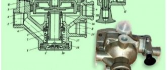
The main elements of the valve (Fig. 7.7) are: accelerator piston 1, upper 2 and lower 11 valves, large 3 and small 9 step follower pistons, elastic element 4, lever 5, pusher 6, thrust bolt 7, springs 8, 10 step pistons, small piston pusher 12. Outputs I and II of the valve are connected through intermediate devices to the brake chambers of the front and rear wheels, respectively; terminals III and IV - with air cylinders of two separate drive circuits of the service brake system. In the initial position (the brake pedal is released), valves 2 and 11 (Fig. 7.7, 6) are closed under the action of their springs, terminal I is disconnected from terminal IV and terminal II is disconnected from terminal III; terminals I and II are connected to the atmosphere through window 13.
When you press the brake pedal (Fig. 7.7, b), the force is transmitted through the system of rods and drive levers to the brake valve lever and then through the pusher 6 and the elastic element 4 to the follower
piston 3. Moving down, piston 3 compresses the spring to close the outlet window when it touches valve 2 and disconnects pin II from the atmosphere, and then lifts valve 2 from the seat. Compressed air supplied to terminal III, through open valve 2, flows to terminal II and then into the brake chambers of the rear wheels until the force of pressing lever 5 is balanced by pressure
compressed air and spring 8 onto piston 3 (a tracking action is carried out in the upper section of the brake valve).
Simultaneously with the increase in pressure in outlet II, compressed air passes through channel “a” in the valve body into cavity A above the accelerating piston 1 of the second section of the brake valve. Having a large area, piston 1 moves down and, with a small pressure in the space above the piston, acts on the stepped piston 9 of the second section of the Brake valve. Moving down, piston 9 compresses spring 10, closes the outlet window when it touches valve 11 and disconnects terminal I from the atmosphere, and then lifts valve 11 from the seat. Compressed air supplied to terminal IV passes through open valve 11 to terminal I and then into the brake chambers of the front wheels. With increasing pressure in outlet I, the pressure in the cavity under pistons 1 and 9 increases, balancing the force acting on piston 9 from above. As a result, a pressure corresponding to the force on the brake valve lever is also established in terminal I, i.e., the tracking action is also carried out in the lower section of the brake valve.
If the upper section of the brake valve fails (there is no pressure in terminal II), the lower section is controlled mechanically through the thrust bolt 7 (Fig. 7.7, d) and pusher 12, fully maintaining its functionality. In this case, the tracking action is carried out by balancing the force applied to the lever 5 from above, with the pressure of air and spring 10 on the small stepped piston 9 from below. Failure of the lower section of the valve (no pressure in port I) does not affect the operation of the upper section.
When the force is removed from the brake pedal, the lever 5 of the brake valve under the action of the elastic element 4 returns to its original position. The stepped piston 3 moves upward by the force of the compressed spring 8, valve 2 sits in the seat and air enters
from the air cylinder to terminal II stops. With further upward movement of piston 3, the outlet window opens and connects output II with the atmosphere through window 13. The pressure in outlet II, and therefore in cavity A of the supra-piston space of accelerating piston 1, falls, pistons 1 and 9 move upward under the action of spring 10, and the valve 11 sits in the seat and the access of air from the air cylinder to terminal I stops. With further movement of pistons 1 and 9 upward, the outlet window opens and connects output I with the atmosphere through window 13.
How to check the brake valve
Procedure for checking the brake system drive valve:
- Check the serviceability of the lamps and buzzer. To do this, you need to press the button located in the control lamp block; it should light up. The buzzer functions properly if at least 1 lamp lights up. Start the power unit and fill the pneumatic drive with air. In operating condition, filling the system takes no more than 8 minutes.
- Inspect the pneumatic system drive for leaks. It is necessary to turn off the compressor and lower the brake pedal. Within half an hour, the pressure level should drop to at least 0.5 kgf/cm². With consumers turned on, the pressure should reach this value within 15 minutes.
- Check the serviceability of the safety valves. A pressure gauge should be connected to the control valve. Then it is necessary to bleed the air flow from the front axle cylinder using a condensate drain valve. The level of pressure drop should be shown by only one arrow; the indicators in the cylinders of the rear cart and the parking brake system should not change.
- Check the serviceability of the pneumatic drive. The pressure gauge readings must correspond to the pressure level in the brake chambers of the rear cart and front axle.
DISASSEMBLY OF THE CRANE
+Before disassembling, the crane must be clamped in a vice. Using round-nose pliers, remove retaining ring 2. From the valve body, remove valve 3 and valve 9 with seal and spring 7. Unscrew bolts 11 from the body. We take out the spring 30 from the body 15 together with the piston 16. Clamping it with pliers, we pull out the large piston 19.
To remove valve 28, you need to remove the locking ring 21 and pull out the valve 22 with rings and spring 26. To remove the elastic element 34, you need to hold the piston 32, unscrew the nut 40 and then pull it out. All disassembled parts must be washed with MS-6TU solution. All elastic bands and cuffs must be replaced with new ones. At the beginning of assembly, all parts must be lubricated with cyatim-221 lubricant.
Brake valve repair
Repair of the KamAZ crane brake mechanism is carried out as follows:
- It is necessary to unpin and dismantle the pin of the traction device.
- Then unscrew the 4 mounting bolts from the bracket.
- It is necessary to unscrew the air lines that lead to the tap. Using a punch, mark the location of the air channels relative to the highways.
- After this, unscrew the 4 bolts from the base plate body using a 12mm wrench.
- Then dismantle the upper part of the faucet body along with the handle and separate the plate.
- Finally, remove the upper piston mechanism.
https://youtube.com/watch?v=A2GR1koL2yo
If the problem is that the faucet hisses, then it is necessary to restore the seal of the piston part. To do this, you need to replace the damping device, which dampens sudden shocks from the handle.
To replace the damper, you need to maintain the previous position of the screw and adjust the gap between the screw and the pushing part of the piston.
If the breakdown was caused by a malfunction of the valve, you need to unscrew the mounting screws, disconnect the housing and pull out the small piston, swinging the large one.
To restore the tightness, it is necessary to isolate the upper and lower sections of the sealing rings, bleed out the air, and replace the damaged parts with new ones.
Two-section brake valve Kamaz malfunction
Malfunctions of pneumatic drive power supplies
When servicing the pneumatic drive of the car brakes, you must first make sure that the system is tight.
Particular attention should be paid to the tightness of connections of pipelines and flexible hoses, since this is where air leaks most often occur.
Places of strong air leakage are determined by ear, and weak ones - using a soap emulsion.
Air leaks from connections of pipelines and brake system devices are eliminated by tightening them, and leaking pipelines and flexible hoses are replaced.
It must be remembered that on cars manufactured since March 1986, pipeline connections are sealed using rubber rings, so the tightening torques of the fittings should be less (Table 1).
If the air cylinders of the brake pneumatic drive are not filled and the pressure regulator vents air into the atmosphere, there may be several reasons:
— the pipeline between the regulator and the safety valves is blocked;
- the pressure regulator is faulty - most often the filter element in it is clogged with oil or ice crystals.
pipeline diameter, mm.
Tightening torque, kgcm
If the air tanks fill slowly and the air pressure does not reach the nominal pressure, then either the compressor or the pressure regulator is faulty.
A malfunction of the compressor cylinder-piston group is also indicated by an increased oil content in the condensate.
Often the cylinders of a separate circuit are poorly filled. The air in each circuit of the brake system passes through a section of its “own” safety valve.
Probably, the safety valve does not allow air into the cylinder or the air supply line to this circuit is clogged. It is also possible that the standard two-pointer pressure gauge is faulty.
KAMAZ 43118 pneumatic system diagram
BRAKE SYSTEM OF KAMAZ VEHICLES – PART 2
Rice. 287. Pneumatic drive of car brake mechanisms mod. 5320: A – control output of circuit IV; B, E – valves of control terminals of the third circuit; C – control output of circuit I; D – control output of circuit II; N – brake control line of a two-wire drive; P – connecting line for single-wire drive; R - main supply line for a two-wire drive; 1 – brake chambers type 24; 2 – parking brake system control valve; 3 – emergency brake release valve for the parking brake system; 4 – auxiliary brake system control valve; 5 – two-pointer pressure gauge; 6 – control lamps and sound signaling device; 7 – control valve; 8 – pressure limitation valve; 9 – compressor; 10 – pneumatic cylinder for driving the engine stop lever; 11 – pressure regulator; 12 – anti-freeze fuse; 13 – double safety valve; 14 - sensor for turning on the solenoid valve of the trailer brake mechanism; 15 – rechargeable batteries; 16 – two-section brake valve; 17 – triple safety valve; 18 – pressure drop sensor in the receiver; 19 – condensate drain valves; 20 – condensing receiver; 21 – air bleed valve; 22 – receivers of circuit II; 23 – pneumatic cylinder for the auxiliary brake system flap drive; 24, 25 – receivers of circuits I and III; 26 – brake chambers of type 20x20; 27 – sensor for turning on the warning lamp of the parking brake system; 28 – energy accumulators; 29 – accelerator valve; 30 – automatic brake force regulator; 31 – trailer brake control valve with a two-wire drive; 32 – two-line valve; 33 – sensor for turning on the brake signal; 34 – trailer brake control valve with single-wire drive; 35 – single safety valve; 36 – rear lights; 37 – disconnect valves; 38, 39 – connection heads type A and type “Palm”
Rice. 288. Diagram of the pneumatic drive of the brake mechanisms of KamAZ-53229, -65115, -54115, -43253: 1 – water separator; 2 - compressor; 3 – cooler; 4 - four-circuit safety valve; 5 – automatic brake force regulator; 6 – pressure regulator; 7 - brake signal switch; 8 - brake valve; 9 – pneumatic cylinders for the damper drive of the auxiliary brake system mechanism; 10 – parking brake system control valve; 11 – proportional valve; 12 - pneumatic cylinder for driving the engine stop lever; 13 – auxiliary brake system control valve; 14 – pressure gauge; 15 – brake chambers type 30/30; 16 – receiver circuit 1Y; 17 – receivers of circuit 11; 18 – condensate drain valve; 19 – brake chambers type 20/20; 20.24 – accelerator valves; 21-two-line bypass valve; 26 switch for the parking brake system warning lamp; 23 – receiver of circuit III; 25 – receiver of circuit I; 26 – switch for warning lamp for air pressure drop in circuit III; 27 – emergency brake release valve
Rice. 289. Diagram of the pneumatic drive of the brake mechanisms of KamAZ-4326 vehicles: 1 – brake chambers of type 24; 2 (A, B, C) – control terminals; 3 – pneumoelectric switch for the trailer solenoid valve; 4 – auxiliary brake system control valve; 5 – two-pointer pressure gauge; 6 – compressor; 7 - pneumatic cylinder for driving the engine stop lever; 8 – water separator; 9 – pressure regulator; 11 – two-line bypass valve; 12-4 circuit safety valve; 13 – parking brake system control valve; 14 – heat exchanger; 15 – two-section brake valve; 17 – pneumatic cylinders for driving the flaps of the auxiliary brake system mechanism; 18 – receiver of circuit I; 19 – consumer receiver; 20 – pressure drop alarm switch; 21 – receiver of circuit III; 22 – receivers of circuit II; 23 – condensate drain valve; 24 – brake chambers of type 20/20 with spring energy accumulators; 25, 28 – accelerator valves; 26 – control valve for trailer brake systems with a two-wire drive; 27 – parking brake system warning switch; 29 – control valve for trailer brake systems with a single-wire drive; 30 - automatic connecting heads; 31 – connection head type A; R – to the supply line of the two-wire drive; P – to the connecting line of the single-wire drive; N – to the control line of the two-wire drive; 31 - pressure drop sensor in the primary circuit receivers; 32 - pressure drop sensor in receivers of the 2nd circuit; 33-brake signal sensor; 34-crane emergency brake release
Rice. 290. Diagram of the pneumatic drive of the brake mechanisms of KamAZ-43118, -65111 vehicles
Rice. 291. Diagram of the pneumatic drive of the brake mechanisms of KamAZ-43101, 43114:1 – type 24 brake chambers; 2 (A, B, C) – control terminals; 3 – pneumoelectric switch for the trailer solenoid valve; 4 – auxiliary brake system control valve; 5 – two-pointer pressure gauge; 6 – compressor; 7 – pneumatic cylinder for driving the engine stop lever; 8 – water separator; 9 – pressure regulator; 11 - two-line bypass valve; 12-4 circuit safety valve; 13 – parking brake system control valve; 14 – heat exchanger; 15 – two-section brake valve; 17 – pneumatic cylinders for driving the flaps of the auxiliary brake system mechanism; 18 – receiver of circuit I; 19 – consumer receiver; 20 - pressure drop alarm switch; 21 – receiver of circuit III; 22 – receivers of circuit II; 23 – condensate drain valve; 24 – brake chambers of type 20/20 with spring energy accumulators; 25, 28 – accelerator valves; 26 – control valve for trailer brake systems with a two-wire drive; 27 – parking brake system warning switch; 29 – control valve for trailer brake systems with a single-wire drive; 30 – automatic connecting heads; 31 – connection head type A; R - to the supply line of the two-wire drive; P – to the connecting line of the single-wire drive; N - to the control line of the two-wire drive; 31 - pressure drop sensor in the primary circuit receivers; 32 - pressure drop sensor in receivers of the 2nd circuit; 33-brake signal sensor; 34-crane emergency brake release
Rice. 292. Diagram of the pneumatic drive of the brake mechanisms of KamAZ-53228 vehicles
The cause of a malfunction of the KamAZ brake system can be a failure of pneumatic devices, violation of adjustments, as well as leaks of compressed air in the pneumatic drive due to leaks in pipeline connections and flexible hoses. Leaks in the pneumatic drive circuits are indicated by glowing warning lamps (see “KAMAZ Controls”) and a buzzer. 4
When the pressure in the circuits reaches above 450–550 kPa (4.5–5.5 kgf/cm2), the lamps should go out and at the same time the buzzer should stop sounding. The time required to fill receivers with compressed air to the nominal pressure should not exceed:
- 6 min. - for auto,
- 9 min. – for a road train at the rated engine speed.
Check the tightness of the pneumatic drive at the rated pressure, the compressed air consumers are turned on and the engine is not running. Locate large air leaks by ear. Minor leaks can be detected by coating the pipe connections with soap emulsion.
When troubleshooting, use Diagrams of pneumatic drive of brake systems, which conventionally depict brake devices and pipelines connecting them.
Diagram of the pneumatic drive of the brake systems of KAMAZ vehicles models 43114,43118,44108 1 – front brake chambers; 2 (A, B, C, D) – control terminals; 3 – electromagnetic valve; 4* – auxiliary brake system control valve; 5 – two-pointer pressure gauge; 6 – compressor; 7* - pneumatic cylinder for driving the engine stop lever; 8 – air dryer with pressure regulator; 9 – regeneration receiver; 11 – two-line bypass valve; 12 – 4-circuit safety valve; 13 – parking brake system control valve; 14 – heat exchanger; 15 - two-section brake valve; 17 - pneumatic cylinders for driving the flaps of the auxiliary brake system mechanism; 18 – receiver of circuit I; 19 – receiver of circuit IV; 21 – receiver of circuit III; 22 - circuit II receivers; 23 – condensate drain valve; 24 – rear brake chambers with spring energy accumulators; 25, 28 - accelerator valves; 26 – control valve for trailer brake systems with a two-wire drive; 27 – parking brake system warning switch; 30- automatic connection heads; R – to the supply line of the two-wire drive; N – to the control line of the two-wire drive; 32 – pressure drop sensor in receivers of the 2nd circuit; 33 – brake light sensor; 34 – emergency brake release valve; 35 – pressure drop sensor in the primary circuit receivers; 36** – brake force regulator; 38 – modulators; 39 – ABS speed sensor; 40 – pressure drop sensor in circuit III; 41 – pressure drop sensor in circuit IV
CRANE ASSEMBLY
We take valve 28 and install it in body 30. We direct the stopper collar 25 towards the conical spring 26. Holding the valve, we put the retaining ring 21 into the groove with round pliers. We install the piston 19, the smaller piston 16, the spring 15, the rubber seal and the housing 13. We tighten the housing 13 with bolts 11 with an engraver.
Next, we place valve 3 in housing 13 and lock it with a ring. Turn the tap 180 degrees and assemble piston 32 with element 34, cuff and plate 35, and tighten pin 36.
The distance between stud 1 and valve 5 should be +0.8 mm and locked with a nut. We insert piston 32 into housing 30 with spring 31 and an o-ring.
brake valve adjustment
How to adjust
The brake valve is adjusted as follows:
- Close the tap.
- Connect a pressure gauge to the connection head.
- Increase the pressure in the receiver to 7.3 kgf/cm².
- Check the pressure gauge readings, which should match the pressure in the receiver.
- If the device shows a low pressure level, check the position of the spring mechanism. It should be pressed against the stop.
- Set the emergency brake system lever to the “On” position.
- Turn the plate clockwise. 1 revolution increases the pressure level by 2 kgf/cm². It is necessary to make the number of revolutions that will make up for the difference in the readings of the pressure gauge and the receiver.
- Set the parking brake to the “Off” position.
- Check the pressure gauge readings.
- Adjust the brake valve drive from the service brake system.
- Lower the brake pedal and adjust the length of the pull rod.
- Lock the fork with the fastening nut so that the lever is in contact with the stop part of the tap.
- Lower the adjusting bolt.
- Adjust the position of the handle so that its upper part touches your finger.
- Adjust the lever stroke by rotating the adjusting bolt.
How to improve your brakes
Repairing the KamAZ brake system and tuning will help improve the performance of this mechanism:
- Replacing standard discs with larger diameter ones. To install them, you need to drill special holes that must coincide with the mounting bolts of the tuning part. In some cases, plates may be required to support calipers over larger disc mechanisms. You should also purchase wheels that are larger in size and width.
- Replacing the standard mechanism with a ventilated disc or device with notches of the same size. Calipers must be installed on each disc using reliable fasteners. This method will help increase the efficiency of the brake chamber by 2 times.
When carrying out work to improve brake performance, the following recommendations must be observed:
- The brake design itself is prohibited from changing at the legislative level. Any changes will be detected during regular technical inspection.
- All parts should be selected only from reliable manufacturers who have passed the certification procedure.
- Tuning can only be done if all elements of the system are in good condition.
How to remove a brake drum
Before performing this procedure, you should wear protection, such as a mask or goggles.
To remove the brake drum, do the following:
- Place the vehicle on a special platform.
- Stop the engine and raise the handbrake.
- Loosen the bolt tension.
- Using a wheel wrench, turn each nut 1 turn counterclockwise.
- Raise KamAZ using a special device.
- Unscrew the bolts and remove the wheel.
- Using a wheel wrench, remove any loose wheel nuts.
- Remove the cap and put all unscrewed fasteners into it.
- Remove the wheel from the guides.
- Loosen the pads by unscrewing the adjuster screw, which is located on the outside of the drum part.
- Turn the drum so that the hole aligns with the adjuster screw.
- Turn the regulator screw clockwise until it stops.
- Remove the drum.
- Using a screwdriver, remove the screws that hold this mechanism to the wheel.
- Pull the drum towards you using a special puller.
- Insert a screwdriver under the flange of the drum mechanism.
- Lightly tap the lever, screwdriver, or the drum itself.
How to adjust
To adjust the brakes on KamAZ you need:
- Check the movement of the brake lever. It should move freely and return to its original position.
- Align the holes in the handle body and the mechanism rod fork by rotating the worm.
- Press the control unit all the way in the direction of its rotation.
- Using bolts and nuts, connect the fixing type bracket to the control unit of the handle. The position of the block should remain the same.
- Rotating the worm, open the brakes until the pads touch the drum mechanism.
- Turn the worm in the opposite direction ¾ of a turn. The gear coupling must work, and the turning torque of the worm must be at least 42 Nm.
- Check the functionality of the handle. To do this, you need to release the brakes of the vehicle in place by pressing the pedal all the way.
- Check the serviceability of the rod. It should move without binding.
- Adjust the stroke of the rod according to the required clearance by rotating the worm.
- Check the uniform rotation of the drum mechanism.
After 2-6 km, inspect the mechanism for heating of the drum device. The temperature should not exceed +60…+80°C.