Happiness cannot last forever, so not all of my on-board photo reports are supplied with a large number of photos. don't blame me.
There are three nuances to the preparation of the lower arms. Look - there are no problems with installing polyurethane silent blocks - using the same jack pin (oh, how useful it was for me in this project!) The main thing is to lubricate the installation places well with waterproof grease (this is not rubber - lubrication is simply necessary here to avoid squeaking during operation!) .
The second note is about restoring the threads in the mounting areas of the lower front suspension arm bracket. 2217-2904026
sort of “pregnant little men” into which the lower ball joint is inserted
After all, it is 99% that when they are unscrewed, half of the M8 rawhide bolt will remain inside the lever, having rusted tightly.
The easiest way to restore the threads is to flip the arms over and swap them around! after all, the thread is often through, you just need to update it with a tap, and the thickness of the lever is quite enough to tighten new bolts (of course, with a strength of 8.8 and with lubricant or thread locker - in this case, the bottom of the thread will be hermetically sealed with the remnants of the old bolt, and the working part of the bolt is protected against corrosion with lubricant or fixative
And third, the most delicious!
These are broken bushings in the beam securing the axles of the lower arms!
In theory, these axles should sit tightly in the bushings. and silent blocks rotate around them in levers. If they are made of rubber, then they rotate due to the deformation of the rubber; if they are made of polyurethane, then they rotate around an axis or inside the lever
In practice, we have 2 cases - First: the axles are embedded in the bushings in such a way that it is simply impossible to get them out. Is it necessary to pick them out for a long time and persistently (even to the point of drilling holes in the bushings and supplying a penetrating liquid inside that eats away corrosion (ordinary vinegar works well)
Second, the axles begin to rotate in the bushings. They wear out on their own and eat away the inside of the bushings in one go.
This is exactly what happened with the old suspension, the lever axis was literally twisted by hand and there was play - the looseness was more than half a centimeter (To solve the problem, a used suspension was purchased, partially disassembled and sent to me for assembly from two
Fortunately, there are plenty of them on sale (especially due to the introduction of gazelle beams) and they cost a penny (about 4,000 for an assembled set)
So, an attempt to install the made lower arms into the beam on the new axle showed that there was still a slight play. How to be in this case?
Do not neglect the caliper, micrometer and probes, but remember that only the right “by eye” is always with you, and the accuracy of “well, something like” is usually quite sufficient. For it is said: “Try it on seven times - it won’t get longer...”
Front suspension of the Sobol car
The suspension on the Sobol is of the independent and spring type, and consists of double wishbones.
The basis of the unit is the cross member - a tubular beam attached to the frame side members. The axles are pressed into the crossmember brackets, and the suspension arms are installed below. The upper suspension arms, like the lower ones, are mounted on the cross member through silent blocks. Shock absorbers, monotube and gas, are located inside the springs. They are non-separable, and therefore in case of malfunctions they often need to be replaced rather than repaired.
Front suspension design of the Sobol car
The front suspension of the Sobol car is independent, spring, on double wishbones, with monotube gas-filled shock absorbers and anti-roll bar
The basis of the suspension is a steel tubular beam-cross member, which is attached to the frame side members with eight bolts and an additional two braces.
Axles are pressed into the crossmember brackets, on which lower, forged suspension arms are installed through silent blocks.
In addition, pendulum steering arms are installed on the brackets.
The upper suspension arms, stamped from sheet steel, are also installed through silent blocks on axles bolted to the cross member brackets.
The suspension springs have unground support coils.
The lower ends of the springs rest on the cups of the lower arms, and the upper ends - through rubber gaskets - rest against the cups mounted on the crossmember brackets.
Shock absorbers are located inside the springs. A silent block is installed in the lower eye of the shock absorber, the axis of which is bolted to the lower arm cup.
The shock absorber rod is attached to the cross member bracket through rubber cushions.
Shock absorbers are single-tube, gas-filled, non-separable design.
To reduce vehicle roll when cornering and improve handling, an anti-roll bar is installed in the front suspension. It consists of a rod, two racks, brackets, rubber pads and fasteners.
A rubber compression buffer is placed on the lower arm bracket, limiting upward travel of the suspension.
The suspension strut is connected to the upper and lower control arms by two sealed ball joints.
A trunnion is attached to the rack, on which two tapered roller bearings of the wheel hub are mounted.
The bearings are adjusted using a nut screwed onto the threaded end of the trunnion.
The bearings are lubricated by grease placed in the hub cavity. They are protected from dirt by a cuff on the inside of the wheel and a screw cap on the outside.
Five bolts are pressed into the hub, to which a wheel with a tubed or tubeless tire is attached with cone nuts. In addition, the front brake disc is secured to the hub with three countersunk screws.
Adjustment of the longitudinal inclination of the wheel (caster) axis and camber angle is done by changing the number of special adjustment brackets located under the front and rear bolts securing the axis of the upper suspension arm.
The toe-in of the wheels is adjusted by changing the length of the side rods of the steering linkage.
Number of adjustment brackets required to change wheel alignment angles
| Number of staples under the front bolt | Number of staples under the rear bolt | Change caster angle | Change camber angle |
| 1 | 0 | +0°35′ | +0°13′ |
| 0 | 1 | –0°35′ | +0°13′ |
| 1 | 1 | 0 | +0°23′ |
| –1 | –1 | 0 | –0°23′ |
| –1 | 1 | –1°10′ | 0 |
| 1 | –1 | +1°10′ | 0 |
Wheel alignment angles for gross vehicle weight
Parameter - Angle
Caster (longitudinal inclination of the wheel turning axis) +4°30'±1° (+3°±1°)*
The difference in the angles of the left and right wheels when adjusting the caster, no more than 0°30′
Wheel camber 0°30'±30′ (+1°00'±30′)*
The difference in the angles of the left and right wheels when adjusting the camber, no more than 0°30′
Toe-in of each wheel to the longitudinal axis of the vehicle from +0°03′ to + 0°10′ (from +0°01′ to +0°08′)*
*In brackets - for a equipped car
How to diagnose the undercarriage and repair the sable undercarriage?
Repair of this system begins with a thorough diagnosis of the vehicle’s condition, which allows us to identify the entire list of existing faults. You should not try to perform this operation on your own - this will require special diagnostic equipment.
Diagnostic work includes not only inspection of the chassis, but also adjacent components, which also take on increased loads during operation. Operations are usually performed in the following sequence:
- chassis check;
- inspection of shock absorbers and steering rack condition;
- identifying possible backlash in mechanisms;
- checking the condition of silent blocks, wheel bearings, discs, calipers, brake pads and drums.
Such a comprehensive check allows you to objectively assess the condition of the car and take appropriate measures to eliminate faults in a timely manner.
History of creation
The all-wheel drive Sobol in passenger version (model GAZ-22177) began rolling off the main car assembly line in 2003. During certification, it was assigned to the “bus” category M2, and this circumstance required the use of ABS in the brake drive since 2007. Since work on setting up the anti-lock braking system for 4x4 vehicles at GAZ had not been carried out at that time, the “22177” model was simply temporarily discontinued from production.
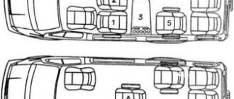
As it turned out, this “temporary” lasted for six long years! As a result, it was only in 2013 that the Bosch 8.1 anti-lock braking system was adapted to the all-wheel drive Sobols, which made it possible to resume production of passenger modifications. So far, dealers are accepting orders only for minibuses with a low roof, a lifting tailgate and a cabin designed for 6 passengers, not counting the driver. This cabin has soft seats with belts and armrests, and a folding table is provided. But there are a couple of drawbacks: the middle row seats are mounted rearward, and the ability to transform is not available as a class. Such a salon is rational for work, but is of little use for proper rest on the road or occasional cargo transportation.
However, there is a way out. Transformable quick-release sofas for minibuses in our country have been produced by Nizhny Novgorod for many years: the backrests of these seats are adjustable in angle of inclination and can be fully folded out, allowing you to organize a comfortable bed for spending the night in the cabin. On the manufacturer’s website, the cost of a pair of sofas starts from 130 thousand rubles, and the installation of a “Riviera” interior is offered as an option by some GAZ dealers.
Front suspension gas 2217 sable do-it-yourself repair
We will try to answer the question: do-it-yourself GAZ 2217 Sable front suspension repair according to the recommendations of a genuine master with the most detailed description.
Gazelle Sable. FRONT SUSPENSION
Front suspension: 1 – lower ball joint; 2 – brake caliper mounting bolt; 3 – brake disc 4 – bracket; 5 – wheel hub bearings; b – hub cap; 7 – hub nut; 8 – washer; 9 – hub; 10 – cuff; 11 – pendulum lever; 12 – transverse steering rod; 13 – cross member; 14 – spacers and adjusting brackets; 15 – bolt securing the upper arm axis; 16 – upper lever; 17 – upper ball joint; 18 – front suspension strut; 19 – spring; 20 – shield; 21 – stabilizer strut; 22 – stabilizer bar; 23 – lower arm; 24 – longitudinal steering rod; 25 – stretching; 26 – extension bracket; 27 – nuts; 28 – washer; 29 – stabilizer cushion; 30 – pillow bracket; 31 – silent block of the upper arm; 32 – axis of the lower arm; 33 – silent block of the lower arm; 34 – nuts; 35 – pillow cup; 36 – stabilizer cushions; 37 – nuts; 38 – pillow cup; 39 – shock absorber cushions; 40 – shock absorber; 41 – shock absorber hinge.
The front suspension is independent, spring, double wishbone, with monotube gas-filled shock absorbers and anti-roll bar.
The basis of the suspension is a steel tubular cross-beam, which is attached to the frame side members with eight bolts and additionally
two stretches. Axles are pressed into the crossmember brackets, on which lower forged suspension arms are installed through silent blocks. In addition, pendulum steering arms are installed on the brackets.
The upper suspension arms, stamped from sheet steel, are also installed through silent blocks on axles bolted to the cross member brackets.
The suspension springs have unground support coils. The lower ends of the springs rest on the cups of the lower arms, and the upper ends, through rubber gaskets, rest against the cups mounted on the crossmember brackets.
Shock absorbers are located inside the springs. A silent block is installed in the lower eye of the shock absorber, the axis of which is bolted to the lower arm cup. The shock absorber rod is attached to the cross member bracket through rubber cushions. Shock absorbers are single-tube, gas-filled, non-separable design.
To reduce vehicle roll when cornering and improve handling, an anti-roll bar is installed in the front suspension. It consists of a rod, two racks, brackets, rubber pads and fasteners.
A rubber compression buffer is placed on the lower arm bracket, limiting upward travel of the suspension.
The suspension strut is connected to the upper and lower control arms by two sealed ball joints. A trunnion is attached to the rack, on which two tapered roller bearings of the wheel hub are mounted. The bearings are adjusted using a nut screwed onto the threaded end of the trunnion. The bearings are lubricated by grease placed in the hub cavity. They are protected from dirt by a cuff on the inside of the wheel and a screw cap on the outside. Five bolts are pressed into the hub, to which a wheel with a tubed or tubeless tire is attached with cone nuts. In addition, the front brake disc is secured to the hub with three countersunk screws.
Adjusting the caster angle and the camber angle is done by changing the number of special adjustment brackets located under the front and rear bolts securing the upper suspension arm axle. The toe-in of the wheels is adjusted by changing the length of the side rods of the steering linkage. These operations require special equipment (optical stand), and therefore must be carried out at a service station. The values of caster and camber angles, as well as wheel toe angles, are indicated at the end of the chapter. The number of adjusting brackets required to change the wheel alignment angles to the required amount is also given there.
The front suspension of the car is independent, spring, lever (with transverse arrangement of arms), with double-acting hydraulic single-tube gas-filled shock absorbers.
The front suspension (Fig. 5.1) is an independent unit, which consists of the following main parts; crossmembers 15. racks 21 with lower 11 and upper 5 levers, springs 22 With parts for their installation and fastening, as well as shock absorbers 33 (see Fig. 5.2).
The suspension unit also includes front wheel hubs 6 (Fig. 5.2) with brake discs 7 and bearings 1, a steering linkage (longitudinal 23, transverse 24 and two lateral tie rods), as well as pendulum arms 22.
The suspension is attached to the car frame with a bolted connection through the cross member brackets and with the help of guy wires 24 (in Fig. 5.1), which absorb longitudinal forces acting from the road.
The front suspension strut is connected to the upper and lower arms by ball joints 12 and 28 (see Fig. 5.2) of a non-separable design.
The suspension arms swing relative to their axes on silent blocks 4 and 12 (see Fig. 5.1).
The upper lever 5 is stamped, with paired silent block bushings. The lower arm axis is attached to the cross member bracket with two bolts through adjusting brackets 18 and spacer washers 17
The lower arm is forged. The right and left lower control arms differ in their spring cup and assembly. The rear and front parts of the levers, as well as the left and right brackets of the levers, are unified with each other. The spring cup is attached to the lever with four bolts, one of which is 35 (see Fig. 5.2). mounted on the rear of the lever, limits the compression stroke. The 3S compression stroke buffer is mounted on the lower arm bracket through a spacer.
The swing axes of the upper and lower arms are not parallel, which reduces the squat of the front of the car when braking.
The suspension spring 34 has unground support coils. The upper end of the spring rests through a rubber gasket 14, repeating the shape of the opera coil, on the upper spring cup, the lower end rests on the lower lever cup,
Shock absorbers 33 are installed inside the suspension springs. A rubber-metal hinge 31 is pressed into the lower eye of the shock absorber, the axis of which is attached with two bolts to the spring cup of the lower arm. The upper end of the shock absorber rod is attached through rubber pads 15 and cups 16 to the suspension cross member.
The anti-roll bar serves to reduce roll when turning and improve handling. The middle part of the stabilizer bar 9 (see Fig. 5.1) is attached to the frame side members through rubber pads 6. The ends of the rod are connected to the lower arms through stabilizer struts 8.
The front suspension of the Sobol car is independent, spring, on double wishbones, with monotube gas-filled shock absorbers and a stabilizer bar. The basis of the suspension is a steel tubular beam-cross member, which is attached to the frame side members with eight bolts and an additional two braces.
Axles are pressed into the crossmember brackets, on which lower, forged suspension arms are installed through silent blocks. In addition, pendulum steering arms are installed on the brackets.
Number of adjustment brackets required to change wheel alignment angles
6.6. Front suspension.
The front suspension is independent, spring, double wishbone, with monotube gas-filled shock absorbers and anti-roll bar. The basis of the suspension is a steel tubular beam-cross member, which is attached to the frame side members with eight bolts and an additional two braces. Axles are pressed into the crossmember brackets, on which lower forged suspension arms are installed through silent blocks. In addition, pendulum steering arms are installed on the brackets. The upper suspension arms, stamped from sheet steel, are also installed through silent blocks on axles bolted to the cross member brackets. The suspension springs have unground support coils. The lower ends of the springs rest on the cups of the lower arms, and the upper ends - through rubber gaskets - rest against the cups mounted on the crossmember brackets. Shock absorbers are located inside the springs. A silent block is installed in the lower eye of the shock absorber, the axis of which is bolted to the lower arm cup. The shock absorber rod is attached to the cross member bracket through rubber cushions. Shock absorbers are single-tube, gas-filled, non-separable design. To reduce vehicle roll when cornering and improve handling, an anti-roll bar is installed in the front suspension. It consists of a rod, two racks, brackets, rubber pads and fasteners. A rubber compression buffer is placed on the lower arm bracket, limiting upward travel of the suspension. The suspension strut is connected to the upper and lower control arms by two sealed ball joints. A trunnion is attached to the rack, on which two tapered roller bearings of the wheel hub are mounted. The bearings are adjusted using a nut screwed onto the threaded end of the trunnion. The bearings are lubricated by grease placed in the hub cavity. They are protected from dirt by a cuff on the inside of the wheel and a screw cap on the outside. Five bolts are pressed into the hub, to which a wheel with a tubed or tubeless tire is attached with cone nuts. In addition, the front brake disc is secured to the hub with three countersunk screws. Adjustment of the longitudinal inclination of the wheel (caster) axis and camber angle is done by changing the number of special adjustment brackets located under the front and rear bolts securing the axis of the upper suspension arm. The toe-in of the wheels is adjusted by changing the length of the side rods of the steering linkage. These operations require special equipment (optical stand), and therefore must be carried out at a service station. The values of caster and camber angles, as well as wheel toe angles, are indicated at the end of the chapter. The number of adjusting brackets required to change the wheel alignment angles to the required amount is also given there.
Spring stiffness classes
Each spring sample is assigned a specific class before leaving the factory. Thus, class “A” is assigned to springs that fall within the upper tolerance range, and class “B” to springs whose height is close to the lower tolerance range.
- Class “A” is assigned the following color markers of spring stiffness - white, yellow, orange and brown.
- Class “B” - black, blue, light blue and yellow color markings for springs.
Springs are marked by color. Table
The stiffness of the springs cannot be determined by the color of the appearance. Many people believe that yellow springs are reinforced, red springs are sports, etc. There is no truth in this. The springs are painted with paint of different colors to protect against corrosion. The stiffness of the springs is determined by markers applied to the outer side of the coil. The table of correspondence between the color marker on the outside of the spring and its stiffness is shown below:
Car spring color coding table
Other chassis malfunctions on the Sobol
Some of the chassis problems in a Sobol car related to elements adjacent to the suspension include:
- Backlashes that are often noted by car owners. This problem affects ball joints, steering gears and steering shaft crosspieces. In addition to the wear of the silent blocks of the levers, their replacement in the springs is also often required;
- Faults related to springs are often diagnosed in Sobols. These cars are susceptible to breaking holes in the earrings and spring brackets. Due to excess load, spring leaves can also simply burst - in this case, they need to be replaced;
- When driving over uneven surfaces, the steering finger joints also break quite quickly, so they may need to be replaced.
Repair work on the chassis of a Sobol vehicle is always carried out as a whole, which allows it to achieve optimal quality.
Suspension front and rear
1. Replacement of the rear shock absorber 1 piece - replacement 400 2. Replacement of the front shock absorber 1 piece - replacement 450 3. Replacement of the driveshaft 300 4. Replacement of the cross with the driveshaft removed - replacement 500 5. Replacement of the rear axle assembly - replacement 5500 6. Replacement of the suspension bearing with the cardan removed 500 7. Replacement of the hub bearing (1 side) 700 8. Replacement of the axle shaft (one) - replacement 350 9. Front springs - replacement 1 side Sable 2500 10. Replacement of the rear axle gearbox 3000 11. Replacement of the rear springs 1500 12. Front springs - replacement * 13. Replacement of the upper arm Sable 1 side. – replacement 600 14. Replacement of the lower lever Sable 1 side. – replacement 2500 15. Replacement of the upper silent blocks one side 1000 16. Replacement of the stabilizer - 1 pc./ 550 17. Replacement of the front hub 700 18. Replacement of the steering trapezoid 2000 19. Replacement of the ball joint 1 – pcs. (Sable) 500 20. Replacement of kingpins (two) * 21. Replacement of kingpins and threaded bushings * 22. Injection 500 23. Replacement of silent blocks lower one side 3000
GAZelle and Gas Sobol
Many owners of Sobols know firsthand about problems with the front suspension: the springs sag, the ground clearance decreases, the arms touch the rubber bumpers on a bumpy road. This problem can be solved in two well-known ways:
Method 1 - the cheapest, put larger spacers under the springs.
Method 2 - more expensive, is to buy new springs and replace them.
But there is another method, little known to everyone - transferring the cups to the top of the lever, which I will talk about below and which I myself used on my Sobol.
Not everyone knows that the bolts securing the spring support cups stretch out during operation and become tired. A gap appears between the lever and the cup; when unscrewing or tightening them, in most cases they break.
Spring cup mounting bolts
Spring cup mounting bolts
Now the process itself.
Let's start disassembling the driver's side. We raise it quite high, put boards under the beam and lower it onto them. We unscrew everything that is needed to free the lower arm, take out the shock absorber, spring and unscrew the spring support cup from the arm. We loosen the nuts of the lower arm so that we can move it even lower.
disassembled, moved the lever as low as possible.
We begin to mark on the cup the places where we need to cut it down so that the cup fits on the lever as needed (watch the video)
After marking the cup, we begin to trim using a grinder. We try the already processed cup on the lever; we also need 4 washers 2.5 mm thick for each cup mounting bolt. A total of 16 washers per side (32 pcs in total). I used VAZ bolts and nuts, sold at any auto store, bought washers at a hardware store. (watch the video)
Many will wonder if the cups have weakened after trimming, etc. , I’ll tell you based on my own experience and mileage of more than 20,000 km after such an alteration, nothing happened to the cups, they didn’t bend, etc., everything is in place.
Next, we proceed to assembly, and at the same time I decided to replace all the ball joints, look at the photo:
assembling the driver's side
assembling the driver's side
everything is collected
Once assembled, we proceed to redo the right side, look at the photo report.
we disassemble in the same way as the driver's side
almost done
ground clearance has increased
The tires are 215/70 R16, the clearance has increased quite well
After all the sides have been assembled, we remove the Sable from the jacks onto the wheels and stretch the levers. Also, don’t forget to do the wheel alignment. If you decide to make a suspension based on this principle, then it is better to use gas-oil shock absorbers.
The springs can be cut into a coil - but this is optional, I did not do this. My springs have 3 marks on them - which corresponds to a certain stiffness class. During operation, I did not identify any shortcomings of this modification; the car listens well to the steering wheel and does not chatter at speed in a rut. (everything must be in good order, no backlash, no broken steering fingers or pendulums, etc.)
After a year of operation, minor shortcomings of this alteration were identified. Namely, this is insufficient downward travel of the suspension. What did you feel when you hit a hole, or when there was a sharp change in the road surface, when you drove off the asphalt onto a section of the road where the asphalt was cut away. It was decided to cut off the coil of the springs.
distance to the bump stop before sawing off the spring coil
We disassemble, take out the springs and cut off the coil.
cut off
We do one side first, then the other. At the same time, I replaced the upper ball joints; they broke after a year of use.
Everything is collected. The stroke of the upper lever increased by 1.5 cm. Thus, the defect was corrected.
Recommendations for choosing springs
Springs of the same class are always installed on a car so that the car does not lose the elastic properties of the suspension and handling. It is also not recommended to install springs of different classes in front and behind the car. This will lead to imbalance of the car at high speeds and when cornering. If there is such a need, then it is allowed to install class “A” springs in the front suspension, and class “B” springs in the rear.
Don't neglect buying more expensive springs, higher class springs. Both the car’s suspension and your condition will thank you on a long, long trip. A softer ride will reduce vibration loads on the driver, which often lead to rapid fatigue and decreased concentration.
6.6.4. Front suspension arms, strut and spring
8. Electrical and additional equipment8. Electrical and additional equipment 8.1. Electrical equipment, checking circuits, replacing fuses. 8.2. Accumulator battery. 8.3. Generator. 8.3.1. Generator repair and voltage regulator. 8.4. Starter, removing the starter and replacing the relay. 8.4.1. Disassembling and checking the starter. 8.5. Ignition system, control unit (controller) of the ZMZ-4063 engine. 8.5.1. Sensors of the ZMZ-4063 engine ignition system, checking and replacement. High voltage wires and spark plugs. 8.6. Lighting, light and sound alarms, headlights. 8.6.1.
Turning lights, tail light and license plate light. 8.6.2. Interior lighting and sound signal. 8.7. Steering column switches and switches. 8.8. Windshield wiper and washer. 8.9. Control devices and ignition switch. 8.10. Ventilation and heating system. 8.10.1. Removal and disassembly of the main heater, tap, radiator, electric fan. 8.10.2. Removal and disassembly of the additional heater, electric pump. 8.11. Features of the design of electrical equipment of cars produced in 2003. 8.11.1. Removal and disassembly of generator 3212.3771 (cars from 2003). 8.11.2.
Replacement of lamps in headlights, direction indicators, headlight adjustment (cars from 2003). 8.11.3. Replacement of lamps in instrument lighting, replacement of speed sensor (cars from 2003). 8.12. Engine control system ZMZ-40522, electronic unit, malfunctions and replacement (cars from 2003). 8.12.1. Sensors of the ZMZ-40522 engine control system, check and replacement (cars from 2003). 8.13. Heating and ventilation system (cars from 2003). 8.13.1. Removing the tap, main heater and disassembling it (cars from 2003).
Using a 22mm socket, unscrew the lever axle mounting bolts a few turns.
We move the axle away from the bracket and remove the adjusting brackets from under the axle, writing down their number and location.
We unscrew the bolts and remove the adjusting washers from under the axle, also recording their location.
Remove the bracket from the inside of the spar.
Remove the lever along with the axle. Replacing silent blocks without special tools is impossible, so we recommend replacing the lever assembly. We install the lever in the reverse order, placing the adjusting washers and brackets in their original places.
We check the wheel alignment angles at the service station.
Removing the lower arm
Remove the front suspension spring (see below “Replacing the suspension spring”).
Using a 32mm wrench, unscrew both nuts of the lower arm axle.
Using a heavy hammer, knock out the axle through the spacer...
...and take it out.
We remove the lever.
Holding the bolts with a 17mm wrench, unscrew the two nuts with a 19mm wrench...
...and disconnect the parts of the lever from the lower spring cup. One of the bolts is shaped. It is a stop for the compression stroke of the suspension. Replacing silent blocks of levers without special tools is difficult, so we recommend replacing the lever assembly.
Install the lever in reverse order.
Removing the front suspension strut
We remove the brake caliper (see section “7.2.3. Components of the front wheel brake system”) without disconnecting the brake hose, and tie it with wire to the stabilizer link. We disconnect the steering rod from the steering linkage lever (see section “7.1.2. Steering shaft universal joints, steering rods and pendulum arms”). Raise the lower arm with a jack until the bump stop of the upper arm lifts away from the stop to relieve the load on the ball joints.
Unscrew the nuts of the ball joint bolts (see section “6.6.2. Front suspension ball joints”). Note:
the lower ball pin nut (castelled) is locked with a cotter pin, and the upper ball pin nut is locked by bending the edge of the brake hose bracket.
We knock out the pins of the ball joints from the mounting holes (see section “6.6.2. Ball joints of the front suspension”).
Remove the strut with the hub along with the steering linkage arm and the lower ball joint. If necessary, remove the hub from the rack (see section “6.5.1. Changing the oil, removing bearings, cuffs, rear axle axles”) and the lower ball joint (see section “6.6.2. Ball joints of the front suspension”). Install the stand in reverse order.
Automobile
Car "Sobol" GAZ-2752, 2217, 2310, 2752, 2217, 2310>> Front suspension
Front suspension
| 1 – lower ball joint; 2 – brake caliper mounting bolt; 3 – brake disc; 4 – bracket; 5 – wheel hub bearings; 6 – hub cap; 7 – hub nut; 8 – washer; 9 – hub; 10 – cuff; 11 – pendulum lever; 12 – transverse steering rod; 13 – cross member; 14 – spacers and adjusting brackets; 15 – bolt securing the upper arm axis; 16 – upper lever; 17 – upper ball joint; 18 – front suspension strut; 19 – spring; 20 – shield; 21 – stabilizer strut; | 22 – stabilizer bar; 23 – lower arm; 24 – longitudinal steering rod; 25 – stretching; 26 – extension bracket; 27 – nuts; 28 – washer; 29 – stabilizer cushion; 30 – pillow bracket; 31 – silent block of the upper arm; 32 – axis of the lower arm; 33 – silent block of the lower arm; 34 – nuts; 35 – pillow cup; 36 – stabilizer cushions; 37 – nuts; 38 – pillow cup; 39 – shock absorber cushions; 40 – shock absorber; 41 – shock absorber hinge. |
Description of design
The front suspension is independent, spring, double wishbone, with monotube gas-filled shock absorbers and anti-roll bar.
The basis of the suspension is a steel tubular beam-cross member, which is attached to the frame side members with eight bolts and an additional two braces. Axles are pressed into the crossmember brackets, on which lower, forged suspension arms are installed through silent blocks. In addition, pendulum steering arms are installed on the brackets.
The upper suspension arms, stamped from sheet steel, are also installed through silent blocks on axles bolted to the cross member brackets.
The suspension springs have unground support coils. The lower ends of the springs rest on the cups of the lower arms, and the upper ends - through rubber gaskets - rest against the cups mounted on the crossmember brackets.
Shock absorbers are located inside the springs. A silent block is installed in the lower eye of the shock absorber, the axis of which is bolted to the lower arm cup. The shock absorber rod is attached to the cross member bracket through rubber cushions. Shock absorbers are single-tube, gas-filled, non-separable design.
To reduce vehicle roll when cornering and improve handling, an anti-roll bar is installed in the front suspension. It consists of a rod, two racks, brackets, rubber pads and fasteners.
A rubber compression buffer is placed on the lower arm bracket, limiting upward travel of the suspension.
The suspension strut is connected to the upper and lower control arms by two sealed ball joints. A trunnion is attached to the rack, on which two tapered roller bearings of the wheel hub are mounted. The bearings are adjusted using a nut screwed onto the threaded end of the trunnion. The bearings are lubricated by grease placed in the hub cavity. They are protected from dirt by a cuff on the inside of the wheel and a screw cap on the outside. Five bolts are pressed into the hub, to which a wheel with a tubed or tubeless tire is attached with cone nuts. In addition, the front brake disc is secured to the hub with three countersunk screws.
Adjustment of the longitudinal inclination of the wheel (caster) axis and camber angle is done by changing the number of special adjustment brackets located under the front and rear bolts securing the axis of the upper suspension arm. The toe-in of the wheels is adjusted by changing the length of the side rods of the steering linkage. These operations require special equipment (optical stand), and therefore must be carried out at a service station. The values of caster and camber angles, as well as wheel toe angles, are indicated at the end of the chapter. The number of adjusting brackets required to change the wheel alignment angles to the required amount is also given there.
Repair of the Sobol front suspension: features of the procedure
Like any other car, the Sobol has a number of typical faults, for which car owners most often turn to the service center to eliminate them. When servicing this vehicle, the following operations are most often required:
- Most often, a malfunction of the chassis is associated with the failure of the king pins. Depending on the extent of their damage, either the damaged element can be restored or it can be replaced with a new one. In a Sobol car this is a simple and inexpensive procedure;
- No less often it is necessary to replace springs and levers in various parts of the chassis mechanism. As a result of high loads, they gradually weaken, which can lead to “sagging” of the car;
- Replacing or restoring CV joints, which stands for angular velocity joints;
- An identical operation is carried out with hub bearings, which break quite quickly when driving on uneven roads. If the integrity of the parts is preserved, as a rule, you can get by with adjusting the bearing - to do this, use a nut that is screwed onto the threaded end of the journal. After adjustment, the elements must be lubricated with grease, which is placed in the cavity of the hub;
- Replacement of silent blocks;
- Replacing shock absorbers, which, as mentioned above, are non-separable in Sobol. Most often they “leak” or the bushings wear out.
- At the final stage of repair, the caster angle of the wheels must be adjusted. In Sobol it depends on the number of brackets that are located under the front and rear bolts securing the suspension axle, or more precisely its upper arm;
- Next, the wheel alignment/camber is adjusted. The specialist consistently changes the length of the side rod of the steering linkage, achieving the desired effect.
It is worth noting that to perform the last two types of work, an optical stand is used, which provides sufficient adjustment accuracy. It is impossible to reproduce its operation in “garage” conditions, so independent repair of the chassis is always a risk for the subsequent safe operation of the car.
Features and purpose of the suspension
The suspension is a set of parts responsible for several key functions in the operation of a car: connecting the wheels to the body and frame, regulating the movement of the wheels relative to the vehicle and the road, as well as dampening the shock and vibration of moving parts due to the operation of shock absorbers. You can buy the main parts of the Sobol suspension in the current catalog at affordable prices:
- beams and racks;
- pins and levers;
- ball joints;
- silent blocks and anthers;
- CV joints and gaskets.
Suspension parts for GAZ Sobol are subjected to serious testing during operation. Difficult road and climatic conditions, careless driving lead to accelerated wear of the main suspension parts. To replace them, it is necessary to use certified parts produced by the Gorky Automobile Plant and other domestic enterprises.
At Gaztechnology you will find high-quality suspension parts and can get them at affordable prices. To do this, place an order directly on the website or by phone with the manager. All catalog items are covered by a 14-day guarantee of return or exchange if a manufacturing defect or non-compliance with the stated parameters is detected.
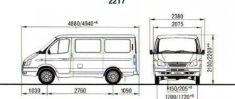
Specifications
| Options | Specifications |
| Dimensions and dimensions: L*W*H, mm | 4840*2075*2200 |
| Internal dimensions of the cargo platform: L*W*H, mm | 1330*1830*1530 |
| Wheelbase, mm | 2760 |
| Front/rear wheel track, mm | 1700 |
| Load capacity, kg | 770 |
| Passenger capacity | 10 |
| Vehicle weight, kg full curb | 1880-1930 2800 |
| Transmission | 5-speed, manual |
| Wheel suspension | front: independent, double wishbone, spring with gas-filled shock absorbers and anti-roll bar; rear: dependent, on two longitudinal semi-elliptic springs with anti-roll bar, with double-acting hydraulic telescopic shock absorbers |
| Engine | ZMZ-4063.10/ZMZ-4026.10/GAZ-560 |
| Working volume cc | 2,464/2,134/2,429 |
| Rated net power, kW, (hp)/rpm. | 103(140)/70(95)/101(137) |
| Maximum torque, Nm/rpm. | 200/250/210 |
Power unit
The following types of engines are installed on the GAZ Sobol 2752 car:
- gasoline engine with a volume of 2.3 liters and a power of 110 hp;
- gasoline engine with a volume of 2.5 liters and a power of 86 hp;
- diesel engine with a volume of 2.1 liter and a power of 95 hp.
| engine's type | Petrol |
| Engine make | EvoTech |
| Engine capacity | 2890.0 (cc) |
| Engine power | 106.0 (hp) |
| Number of cylinders | 4 |
Transmission
Rapid failure of the gearbox, especially in cargo versions operating under overload. Transmission: mechanical 5-speed. Rear drive.
Suspension
- The front suspension is independent, double wishbone, spring with gas-filled shock absorbers and anti-roll bar.
- The rear is dependent, on two longitudinal semi-elliptic springs with anti-roll bar, with double-acting hydraulic telescopic shock absorbers.
Steering
The steering is of the “screw-ball nut” type, with a built-in hydraulic booster, and the steering column is adjustable.
front SUSPENSION Gas-2217. (Catalog No. 2217-2901012)
The front suspension is independent, spring, double wishbone, with monotube gas-filled shock absorbers and anti-roll bar.
The basis of the suspension is a steel tubular beam-cross member, which is attached to the frame side members with eight bolts and an additional two braces. Axles are pressed into the crossmember brackets, on which lower, forged suspension arms are installed through silent blocks. In addition, pendulum steering arms are installed on the brackets.
The upper suspension arms, stamped from sheet steel, are also installed through silent blocks on axles bolted to the cross member brackets.
The suspension springs have unground support coils. The lower ends of the springs rest on the cups of the lower arms, and the upper ends - through rubber gaskets - rest against the cups mounted on the crossmember brackets.
Shock absorbers are located inside the springs. A silent block is installed in the lower eye of the shock absorber, the axis of which is bolted to the lower arm cup. The shock absorber rod is attached to the cross member bracket through rubber cushions. Shock absorbers are single-tube, gas-filled, non-separable design.
To reduce vehicle roll when cornering and improve handling, an anti-roll bar is installed in the front suspension. It consists of a rod, two racks, brackets, rubber pads and fasteners.
A rubber compression buffer is placed on the lower arm bracket, limiting upward travel of the suspension.
The suspension strut is connected to the upper and lower control arms by two sealed ball joints. A trunnion is attached to the rack, on which two tapered roller bearings of the wheel hub are mounted. The bearings are adjusted using a nut screwed onto the threaded end of the trunnion. The bearings are lubricated by grease placed in the hub cavity. They are protected from dirt by a cuff on the inside of the wheel and a screw cap on the outside. Five bolts are pressed into the hub, to which a wheel with a tubed or tubeless tire is attached with cone nuts. In addition, the front brake disc is secured to the hub with three countersunk screws.
Adjustment of the longitudinal inclination of the wheel (caster) axis and camber angle is done by changing the number of special adjustment brackets located under the front and rear bolts securing the axis of the upper suspension arm. The toe-in of the wheels is adjusted by changing the length of the side rods of the steering linkage. These operations require special equipment (optical stand), and therefore must be carried out at a service station. The values of caster and camber angles, as well as wheel toe angles, are indicated at the end of the chapter. The number of adjusting brackets required to change the wheel alignment angles to the required amount is also given there.