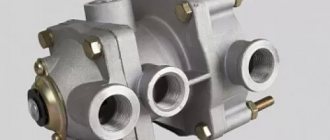
Brake force valve on a semi-trailer
This is the name of the pneumatic unit that controls the reaction of the PP brakes to the signal coming from the truck tractor.
Structure
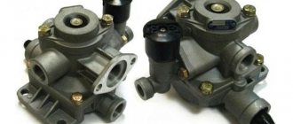
The brake valve (TC) PP can be single- and double-wire. On modern trailed vehicles (Atlant, Knorr, Fruhauf, Schmitz, Krona Tonar, Maz, KamAZ) a more complex two-wire unit is most often installed, so we will consider it.
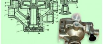
Structurally, the TC consists of a body in which large and small staged pistons, upper and lower valves, and a piston pusher are located. The unit also contains a lever, a pin, an elastic element, a hole for unloading and a screw for adjusting the operation, which allows you to adjust the braking forces on the semi-trailer.
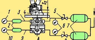
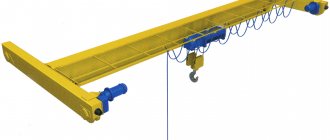
Two-line semi-trailer brake system
According to the diagram, one terminal is connected to the brakes of the front wheel axle, the second - to the rear. Another output leads to the trailer brake release valve, which, through a pressure control valve, transmits a signal to the brake force regulator (PTC), popularly called a submarine or sorcerer.
Purpose
The trailer TC serves to control the braking system of a non-self-propelled vehicle after receiving a command from the truck driver’s cab.
This unit also connects the PP brake system automatically when the pressure in the air line drops to a critical level, releasing excess pressure through an atmospheric valve.
Operating principle
The brake signal is transmitted from the truck cab. After pressing the pedal, the braking force is transmitted through the semi-trailer's main valve using compressed air.
The valve valve, in response to a command, directs air from the assembly to the terminals. Through another hose, the air mixture under pressure is directed to the brake valve, where it exerts force on a large piston, which is activated under the influence of a spring and air pressure, balancing the middle piston, the pressure in the air duct, after which the brake mechanisms are activated.
When the brake pedal is released, air is released through a specially designed hole located in the valve. The spring presses on the piston, it lowers, opening the valve hole.
After the pressure drops, the system disinhibits.
To start the parking system, the valve on the brake force regulator (submarine) opens, and through the hole in the trailer brake release valve, air flows out, connecting the brake mechanism.
A pressure ratio valve is installed between the PTC and the brake release valve, which controls the closure of the air ducts when the pressure drops to critical values, so that spontaneous braking does not occur.
Changing the level of compressed air pressure and adjusting the brake valve of a semi-trailer is done using a special screw.
Brake valve in single line system
The brake force valve on a semi-trailer uses 1 connecting head when connecting the auxiliary vehicle to the tractor using one line.
With this design, the system operates simultaneously as a control and energy system.
When the pressure in the mechanism decreases, the braking effect on the semi-trailer axles increases.
In a single-drive structure, the brake valve consists of:
- piston;
- diaphragm;
- valves for air exchange (inlet, outlet).
Principle of operation
How to replace the heater valve on a VAZ-2109 yourself.
Made to control the actuators of the working brake system of a car, ZIL-130, as well as to turn on the control valves of the trailer brake system.
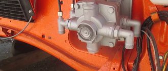
The brake valve is mounted on a bracket attached to the frame side member. The air exits the tap downward through terminal 5.
The brake valve has two independent sections arranged in series. Terminals 1 and 2 of the valve are connected to the receivers of the separate drives of the service brake system.
two-piece brake valve
The force from the brake valve lever is transmitted through the rubber elastic element 31 to the upper piston 30. Moving down, the piston closes the outlet hole of the valve 29 and then lifts it off the seat. Through output 3, compressed air enters the brake chambers of the rear wheels until the force of pressing the lever is balanced by the pressure of compressed air on the piston 30 from below.
Simultaneously with the increase in pressure in outlet 3, compressed air through channel A in the valve body enters cavity B above the large piston 28 of the second section of the brake valve. The piston, which has a large area, moves downward with a slight pressure in the above-piston space and acts on the small piston 15. As the piston moves, the outlet of the valve 17 closes, and then it comes off the seat. Compressed air through port 4 enters the brake chambers of the front axle wheels.
When the pressure in port 4, and consequently in cavity C under pistons 15 and 28, increases, the force acting on the pistons from above is balanced. Thanks to this, a pressure corresponding to the force on the brake valve lever is also established in pin 4 (following action).
If the circuit is damaged and if there is no pressure in output 3 of the first section, the force from the brake valve lever will be transmitted through the pin 11 directly to the pusher 18 of the small piston. Thus, the second section will be controlled mechanically, not pneumatically, and will remain fully operational.
If another circuit is damaged and if there is no air in terminal 4 of the second section, the first section works in the same way.
The drive of the two-section brake valve consists of a pedal connected by a rod to the brake valve lever. The required position of the pedal on the cabin floor is established by changing the length of the rod using a threaded fork. The pedal is returned to its original position by a spring.
PRINCIPLE OF OPERATION
disassembling the brake valve
Trailer release valve
9.17. Trailer release valve.
Release of the brake system for movement of the semi-trailer in the uncoupled state. In addition to the existing double release valves, new variants are available in which both the "travel" and "locked" positions can be secured with a safety pin. The appearance and structure are shown in Figures 248 and 249.
When coupling a trailer to a tractor, make sure that the piston (a) is not in the “park” position; if this is the case, the piston must be manually moved to the “drive” position. When the coupling heads are engaged, compressed air enters through port 1-1 into chamber A. If the piston (c) is still in the “disengaged” position, it is moved to the “travel” position by the supplied compressed air. Compressed air penetrates through port 21 to the trailer brake valve and then into the trailer receiver.
From the receiver, compressed air enters through port 1-2 into chamber B, opens the return valve (b) and through chamber C and port 22 penetrates the downstream connected two-line quick release valve and brakes the chambers of the spring energy accumulators of the Tristop® cylinder.
Figure 248 a. Appearance
Figure 248 b. Structure and symbol
In the uncoupled state, pin 1-1 and thus chamber A are disinhibited. To release the service brake, the piston (c) is pushed in all the way manually using the drive handle. Thus, the passage from pin 1-1 to pin 21 is blocked and a connection is established between chambers A and pins 1-2.
Compressed air supplied from the receiver to terminals 1-2 passes through terminal 21 to the trailer brake valve and moves the latter to the “movement” position, which releases the brake chambers.
When the parking brake is applied, the piston(s) is extended. The compressed air in chamber C and at outlet 22 exits through the air vent hole 3 to the outside. The further connected quick release valve switches and the chambers of the spring energy accumulators of the Tristop cylinders are released.
Figure 249. Overall dimensions. Terminal designations: 11 — energy supply, 12 — energy supply (Receiver), 21 — energy extraction (trailer brake valve), 22 — energy extraction (spring energy accumulator cylinder), 3 — pressure relief channel
Source
What is a parking brake valve?
How to check the GTZ? signs of master brake failure
Parking brake valve (hand brake valve) - a control element of the brake system with a pneumatic drive; a manual valve designed to control vehicle brake release devices (spring energy accumulators) that are part of the parking and spare or auxiliary brake systems.
The parking and spare (and in some cases, auxiliary) brakes of vehicles with pneumatic braking systems are based on spring energy accumulators (EA). The EAs create the force necessary to press the brake pads against the drum due to the spring, and the brake release is carried out by supplying compressed air to the EA. This solution ensures the possibility of braking even in the complete absence of compressed air in the system and creates conditions for safe operation of the vehicle. The air supply to the vehicle is controlled manually by the driver using a special parking brake valve (or simply a manual air valve).
The parking brake valve has several functions:
- Supply of compressed air to the EA to release the vehicle brakes;
- Release of compressed air from the EA during braking. Moreover, provision is made for both complete bleeding of air when applying the parking brake, and partial bleeding when the spare/auxiliary brake is operating;
- Checking the effectiveness of the parking brake of road trains (tractors with trailers).
The parking brake valve is one of the main controls of trucks, buses and other equipment with pneumatic brakes. Incorrect operation of this device or its breakdown can have tragic consequences, so a faulty faucet must be repaired or replaced. To correctly select a new crane, you need to understand the existing types of these devices, their design and operating principle.
Advice from experienced drivers
When questions arise with the pneumatic brake system and there is no time to contact a specialized service, you can search for a solution to the problem online in specialized forums or watch a thematic video on YouTube.
If the sorcerer hisses, the cameras extend the ratchets, the PP slows down, smells like rubber, and when driving without a load, the non-self-propelled vehicle goes into a skid, experienced drivers advise performing the following actions:
- disassemble and clean the RTS;
- see if the brake force valve on the semi-trailer needs adjustment;
- buy a new faucet, which costs about 10–12 thousand rubles;
- check the control valve.
In order to avoid problems with brakes on non-self-propelled vehicles, it is necessary to regularly service the equipment at a specialized service center and check components and systems before a long journey. If the semi-trailer does not release the brakes well, look for the reasons.
Two-section option
Replacing the heater valve VAZ 2113, 2114, 2115
A two-piece valve consists of several parts, such as a drive, a follower, and compressed air inlet and outlet valves. These parts are located in one housing, divided into several parts, one of which contains the drive and follower, and the second contains the inlet and outlet valves. The body is separated by a special diaphragm made of durable rubber.
The tracking device is in conjunction with both the crane drive and the brake pedal, and consists of a spring and a rod. The rod, in turn, is located above the seat in the exhaust valve and the tube, which is located in the glass, resting against the diaphragm.
The glass has a hole that provides communication between the atmosphere and the body. The intake and exhaust valves look like rubber rings and cones, which in turn rest against the seats.
Work specifics
During braking, the valve compresses the gas to a certain degree until the reaction under the piston equals the force applied to the membrane. The valve in such a situation participates as a controller.
When compressed air passes to the working terminals, the pressure inside the valve cavity exceeds the control values of the output force by 20–100 kPa and the advanced action of the brakes is triggered. The required pressure value can be adjusted by turning the screw.
A single safety valve in the system is used to stabilize pressure in air cavities when a sudden and rapid decrease in pressure in the lines occurs.
Also, the OZK is entrusted with the mission of preventing gas leakage from the system when the pressure in the vehicle’s main air drive drops. This helps prevent the trailer wheels from inadvertently braking while driving.
The single valve is set to bypass air if the outlet pressure approaches 550 Pa. The compressed gas penetrates through the outlet into the working cavity below the membrane, then its path continues in the cavity in front of the valve, and then the compressed volume of air is sent to the outlet into the main line. The required pressure is adjusted using the adjusting screw.
Malfunctions
Breakdowns occur in any technology. Wabco brake systems can detect them quickly. Especially if the trailer is connected to EBS. The system is capable of self-testing and detecting faults.
Signs
You can see the breakdown by the following signs:
- continuous operation of the air compress, during which air is constantly pumped into the system;
- lit buttons on the dashboard that indicate problems;
- strange knocking in brakes and tires, squeaking;
- untimely braking;
- the tendency of vehicles to skid when braking.
Reference! The yellow button means limited control of the system, and the red button means the EBS is partially connected, its operation has slowed down and dropped below acceptable limits.
Causes
The appearance of one of the above symptoms indicates that the Wabco system has failed
At this stage it is important to find the cause of the breakdown
There may be several of them:
- failure of EBS or ABS;
- improper operation of transport;
- self-repair (for example, some try to repair the brakes on a Schmitz or Krone trailer, reading advice from various forums);
- lack of regular maintenance.
Troubleshooting
Repairs must be carried out only at specialized service stations. Troubleshooting yourself may damage the system even more.
Lack of technical inspection and untimely repairs lead to:
- emergency situation in case of brake failure, increasing braking distance;
- brake failure;
- malfunction of electronics.
Specialized service stations offer:
- diagnostics of faults in trailed ABS, ESB, pneumatic braking systems from Wabco;
- repair of the brake release valve;
- searching for faulty sensors;
- search for non-working semi-trailer cranes;
- setting braking parameters;
- firmware of a working TABS-E WABCO modulator, etc.
Selection, replacement and maintenance of the brake air distributor
The brake air distributor is constantly subjected to high loads; gaps in its moving parts increase, which can cause air leaks, poor performance, or, on the contrary, spontaneous brake application. In case of any problems, it makes sense to replace the assembly.
When choosing an air distributor, you should follow the recommendations of the trailer manufacturer and install units of certain models and catalog numbers. However, today the market offers a wide selection of original air distributors and their analogues with improved characteristics. Therefore, in a number of cases, it may be justified to install an analogue, but in order to avoid problems in the future, it is necessary to choose analogues with suitable connection dimensions and characteristics.
With the correct selection and installation of the air distributor, the brakes of a trailer or semi-trailer will work reliably and efficiently in any conditions, ensuring the safety of the road train.
Semi-trailer braking system
This is the name of a set of components and parts that are interconnected and ensure the creation of forces that impede the movement of the PP.
Semi-trailer braking system
Varieties
According to the operation pattern, brake systems are divided into 5 types:
- Hydraulic. To slow down the movement, a special liquid is used to activate the structure.
- Electric. Contactless braking is performed by connecting mutually influencing magnets.
- Frictional. The work is carried out by activating the friction force using brake mechanisms.
- Motor. Ensures that the vehicle stops when the engine speed decreases.
- Pneumatic. Here the brakes are activated by air action.
The latter mechanism has long been used in semi-trailers.
Pneumatic braking system for semi-trailer
Operation
The pneumatic system is activated by an actuator, which is a collection of parts and devices that provide braking.
The brake pneumatic drive (TPA) has 2 components:
- energy, responsible for the energy supply of the system;
- control, transmitting a command from the truck brake (TGA).
The TPP has a supply circuit responsible for preparing air for use in the pneumatic system, which includes:
- Compressor (responsible for air pressure in the structure).
- A pressure regulator that maintains the parameter value within normal limits.
- An air dryer that functions as a filter, purifying the supplied air from gasoline, oil, and water vapors. Additionally it works as a receiver (a technical vessel that can withstand increased pressure values of gaseous media).
- Safety four-circuit valve:
- distributes air from one flow to: 1) two perimeters of the TGA; 2) the structure of the control panel, which is responsible for the activation of emergency and parking brakes; 3) air suspension, additional TPP;
- controls the uniformity of air distribution within the perimeters;
- if the integrity of the air pipeline is violated in one part, the TPP provides standard pressure in others.
In accordance with the TPP diagram, it is started by pressing the brake pedal. As a result, control and energy commands are sent to the truck wheel braking mechanisms and to the trailer actuators.
The control parts of the TPP can be a semi-trailer brake release valve, regulators for various purposes, relay valves, etc.
The actuators are diaphragm or energy-storage brake devices.
On a note. The structure of the brake system usually includes one common pressure gauge or separate ones for TGA and TPP, and lights are displayed on the driver’s panel that signal deviations in the system of air pressure values.
Car brake system care
As one of the most important components, the car's braking system requires constant attention and care. Here, literally any malfunction can lead to unpredictable consequences on the road.
Some diagnoses can be made based on the behavior of the brake pedal. Thus, an increased stroke or a “soft” pedal most likely indicates that air has entered the hydraulic drive system as a result of a brake fluid leak. Therefore, it is necessary to periodically monitor the liquid level in the tank.
Its increased consumption may be a consequence of damage to hydraulic hoses and tubes, as well as ordinary evaporation over time. This causes air to enter the system and cause brake failure.
Parts that have become unusable must be replaced, and the system will have to be pumped by bleeding air from each working cylinder on the wheels and adding fluid. The process is long and tedious. When the car pulls to the side when braking, it indicates a possible failure of one of the working cylinders or excessive wear of the linings on a particular wheel. If the brake mechanisms are dirty, a characteristic noise may occur when you press the pedal.
All these malfunctions can be easily fixed independently or by contacting a service center. And to minimize the troubles described above, take care of your brakes and use engine braking more often, especially on steep and long descents. Prolonged activation of the main working system leads to overheating of parts and causes various breakdowns.
What else is worth reading
How the car clutch works
Parking brake does not work
Clutch master cylinder
Muffler device Clutch reservoir
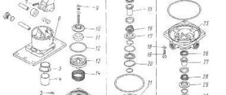
CRANE ASSEMBLY
We take valve 28 and install it in body 30. We direct the stopper collar 25 towards the conical spring 26. Holding the valve, we put the retaining ring 21 into the groove with round pliers. We install the piston 19, the smaller piston 16, the spring 15, the rubber seal and the housing 13. We tighten the housing 13 with bolts 11 with an engraver.
Next, we place valve 3 in housing 13 and lock it with a ring. Turn the tap 180 degrees and assemble piston 32 with element 34, cuff and plate 35, and tighten pin 36.
The distance between stud 1 and valve 5 should be +0.8 mm and locked with a nut. We insert piston 32 into housing 30 with spring 31 and an o-ring.
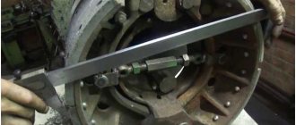
brake valve adjustment
Brake control valve
This is the name of the mechanism for monitoring the TPP during the braking of a truck and automatically controlling the structure in emergency situations (for example, reducing pressure parameters in the system).
Semi-trailer brake valve
Description
The semi-trailer brake valve has 3 main elements:
- main control valve;
- disconnect valve (2 pcs.);
- connection heads (2 pcs.).
Control valve
A command passes through it to the brake pneumatic drive of the semi-trailer.
The three-section device consists of:
- two pistons of different sizes, equipped with springs;
- holes for air release (discharge);
- a cylindrical rod connected to a slider (rod);
- screw for adjusting the pressure.
The principle of its operation:
- When the brake pedal is in the standard position, air pressure locks the rod and piston. The inlet and control valves are closed.
- After pressing the pedal, air is pumped into the line, which, acting on the piston, compresses the spring, which, in turn, pushes the rod, activating the TPP.
- During the release process, the air is released, the spring is straightened, and the wheels are released.
By changing the position of the adjusting screw, the required air compression in the TPP is established (level 20–100 kPa).
Single safety valve
Its function is to prevent compressed air from leaking out of the semi-trailer's brake mechanism when the pressure in the connecting air ducts decreases.
The valve regulates the pressure parameters in the receiver. When the pressure in the air ducts decreases to critical values, the device closes the flow of air into the area where the PP release valve is located.
Isolation valve
This is the name of a device that can be used to block the air flowing through the main line from a truck tractor.
When the valve handle is positioned in the direction of the air duct, the system is open. With the handle raised perpendicular to the axis, the TPP is isolated from the TGA and the truck and trailer can be uncoupled.
Palm connection heads
They are used for a hermetically sealed connection between the air line of a truck and a semi-trailer.
In fact, these Palm parts are a valveless flange connection. Rubber gaskets are used at the joints. The connection is fixed by inserting one head into another. Then one device rotates relative to the other until the protrusion of the inserted part fits into the groove of the female one.
Such connections are used for MAZ, KAMAZ, OdAZ, KRAZ.
Craftsmen replace worn-out Palm heads with hydraulic connectors of the appropriate size. Such devices have been developed for docking structures of spacecraft and submarines.
Palm connection heads
System operation during braking
When the driver presses the tractor's foot brake:
- the brake valve, consisting of two sections, is activated;
- the pressure in the truck brake chambers and in one of the control lines of the Chamber of Commerce and Industry increases;
- with a two-wire drive, after the semi-trailer's PTS valve is activated, air from the receiver enters the control valve and the brake line;
- the single-drive system releases air from the semi-trailer line through the brake valve, after which the PP is braked.
General characteristics of the braking system
The Wabco semi-trailer brake system consists of high quality materials. Spare parts undergo mandatory testing.
Advantages of Wabco brakes:
- keep the loaded trailer in a safe position during stops;
- slow down vehicles without sliding as much as possible;
- optimize braking distance;
- have functional air suspension;
- installed on all types of trailers and semi-trailers;
- capable of conducting intelligent analysis of information and then converting it into functions, of which there are more than 40.
Wabco auto parts are numbered. An example is shown in the figure.
WABCO brake system.
The numbers consist of 10 digits (in the figure they are labeled 2,3,4).
- The numbers indicate the date of manufacture.
- Six digits determine the type of device.
- Indicates an option.
- Indicates the condition of the spare part.
In the picture, the condition of the spare part is indicated as 0. The number indicates that the part is new.
Here are the values for other numbers that can be specified instead of 0:
- 1 – the device is new, but not completely, but only part of it;
- 2 – indicates a repair kit or assembly unit;
- 4 and 7 – accessories and spare parts, respectively.
The numbers 001 in the figure indicate the original part number.
Components
Wabco brakes consist of:
- Wabco semi-trailer brake valve. Provides pneumatic and electrical signals that correspond to the required deceleration value;
- Wabco control unit. Controls the brakes;
- acceleration valve. Regulates pressure in the front axle;
- braking unit. It is a combination of a brake valve, a control unit and a proportional accelerator valve;
- semi-trailer brake control valve. Regulates the pressure output at the locations where the connection heads are located;
- pressure regulator. Controls the force of air pressure in the pneumatic system.
Principle of operation
Wabco produces two types of brake systems for semi-trailers:
- EBS;
- ABS.
Wabco's EBS brakes are electronically controlled.
EBS brakes.
The operating principle is as follows:
- The electronic unit is responsible for the entire system. The main signals are sent from it.
- On the brake cylinders in the valves, the pressure indicated by the signals is reached.
- Speed sensors regularly provide wheel speed data to the EBS system.
- In the event of failures at the same time, all valves function as if a conventional pneumatic system was used. After which the reserve pressure begins to operate in those brake cylinders where the pneumatic system is located, but with some delay.
- The pneumatic system cannot operate simultaneously with the load sharing valve. For this reason, a certain amount of compressed air exerts resistance, thereby creating a strong braking force on the rear axle.
- In this case, the spare valve stops the operation of the pneumatic system in the rear cylinders on the axle.
- Under such conditions, EBS functions quietly and is not disinhibited.
EBS is also equipped with other brake control processes that can detect any deviations.
Principle of operation:
- At the start of a move, while driving or when stopping, the ABS is tested by the main operating processes.
- These processes transmit a signal to the driver that there is some kind of malfunction through the control lamp.
- If necessary, the functional system disables ABS and individual components.
- In this case, the effect of the normal brakes is maintained, but the effect of the anti-lock device is limited or lost.
- Power transistors receive the signals and then transmit current to the magnetic valves.
- The magnetic valve is activated and in milliseconds increases, decreases or maintains the operating pressure in the brake cylinders (regardless of the pressure created by the air distributor), due to which braking is carried out.
Scheme
There are two versions of Wabco's EBS: APAC and Standard. Here are the operating diagrams for each.
Diagram of the EBS3 "ARAS" system (4S/4M configuration)
System diagram EBS3 “Standard”/configuration 6S/6M
ABS brake systems also have two versions C and D.
ABS/ASR (version C)
ABS/ASR (version D)
Main components of an air brake system
The brake system under discussion is divided into several main components, thanks to which the entire assembly can function properly. Naturally, the list of mechanisms below is incomplete, but, as already mentioned, it will contain the most important things:
- Control drive - this brake system implies the presence of pneumatic drive elements by the control drive. With the help of these parts, automatic or intentional regulation of some parts of the energy drive is carried out, which we will discuss in the next paragraph.
- Energy drive - this mechanism of the pneumatic brake system is a set of elements (parts) due to which the control drive is enriched with pressurized air. Thus, the mechanisms presented in the first two paragraphs (this and the previous one), so to speak, complement each other.
- The brake is the most “central” device! It is here, in this mechanism, that all the forces that resist further movement of the machine in any direction are concentrated. There are several different types of brake:
- Friction - a stopping value appears during the contact of two parts of a vehicle that are moving towards each other.
- Electric - the same frictional forces arise under the influence of an electromagnetic field, but the objects do not touch.
- Hydraulic - here again there are two objects moving towards each other, but interaction occurs when the pressure in the liquid between them increases.
- Motor - the braking value increases as a result of the fact that the engine artificially increases the braking effect, while the kinetics is transmitted directly to the wheels of the car.
- Compressor - many people have come across a similar device in everyday situations not related to cars. Essentially, it is an air pump that is responsible for ensuring that the brake system receives the required amount of air, as well as regulating the pressure within the system. This mechanism contains a pressure regulator, which is charged with the mission of monitoring and controlling the supply of compressed oxygen to the compressor, so that the values fluctuate within the limits strictly specified by the developers. If the sensor readings are violated, the system may not be able to withstand it and fail, as a result of which there is a chance of a malfunction in the truck’s braking system.
- The compressor also contains an air dryer, the main task of which is to prepare air directly for the pneumatic system, removing from it excess moisture molecules, evaporation from water, as well as other harmful impurities, such as oil deposits, etc.
It is also worth saying that the vast majority of modern dehumidifiers combine, in addition to the main functions, also a regenerating function, which means that their components also include a receiver.
The braking system can be equipped with another interesting unit, but it is not used everywhere, and is found mainly in serious configurations; it is called an anti-freeze fuse. The principle of its operation and purpose are very simple; in the cold season, this device mixes a special chemical composition into compressed air cylinders. Thus, condensation, which in any case will be present on the system parts, will not freeze and create additional problems.
Malfunctions
When operating a vehicle, the following breakdowns may occur:
- low braking efficiency;
- uneven braking of the wheels of the right and left sides;
- jamming of service or parking brakes (brake jam);
- increased travel of the parking brake handle.
An increase in braking distance can occur due to a large gap between the pads and the brake drum (TB), due to wear of the pads or insufficient output of the rod at low pressure in the pneumatic system. If such a malfunction appears after repairs associated with replacing the pads, then there is a high probability of oiling of the friction material or the inner surface of the brake pad.
In most cases, a car skidding during braking occurs due to a large difference in the strokes of the brake rods installed on one axis or the shaft getting stuck in the expansion cam bushings in the brake pad block.
Slow release most often occurs due to a broken or stuck return spring in the brake cylinder. The cause of such a defect may also be incorrect adjustment of the brake pedal. Therefore, the brake valve lever does not reach the stop. Due to the breakdown of the brake pad tension springs, spontaneous braking may occur, and a characteristic knocking sound in the wheel will be heard when driving.
When driving a truck with a trailer, there may be a delay in the latter's braking. This is due to incorrect installation of the adjusting ring in the brake valve. The same failure is typical for a stuck piston in the trailer air distributor.
It must be remembered that a breakdown in the steering will only lead to a loss of control of the car, and a vehicle failure will lead to the impossibility of stopping it, which will inevitably end in an accident.
Braking
The lower section is responsible for stopping.
The essence of the process comes down to the following: the air that has penetrated the chambers presses on the diaphragm, which compresses the internal spring. Then the pressure goes to the pusher and the expansion cam. The cam roller turns and pushes the brake pads apart, causing the car to stop. By bringing the pedal to its original position, the springs return to their places and the remaining pressure is released.
Parking system
The parking brake, also known as the handbrake, is an integral part of control. This system keeps the car in place even on an incline. To relieve pressure in the spring energy accumulator (EA) of the cylinder, the driver must lock the handbrake in a certain position. EA provides voltage to the system so that the pads are pressed tightly against the drum.
Thanks to this process, it is possible to stop the truck even if there is no air pressure in the pneumatic system, which guarantees safe control of the tractor. If the faucet is damaged, it should be replaced as soon as possible. Considering the design and number of outlets, there are two types of taps: by design - with a rotary handle or a tilting one.
The truck crane mechanism has four outlets. The valve handle, squeezed all the way, allows air pressure to move freely from the receiver part to the energy accumulator, as a result of which the road train is released.
Moving the handle to the opposite position forces the valve to direct the air flow to another part so as to block its access from the receiver. As a result, the air energy is reduced, the springs are stretched, and braking occurs.
Assistance system
Assistance system.
In the event of a failure of the working brake circuits, the road train can brake using the spring energy accumulators of the cylinders. The elastic force compresses them to suspend them.
The pressure is partially released to the desired level. For example, KamAZ installs four mechanisms at once that have a common design, but operate in isolation from each other: main or working, spare, parking and auxiliary.
If one or two systems fail, the driver is able to stop a multi-ton truck in any conditions.
Brake valve for MAZ trailer
Spare part trailer brake air distributor with brake release valve MAZ, KamAZ
Purpose: Designed to control the brakes of a vehicle trailer in the operating braking mode of a trailer or semi-trailer, and to release the brakes of a single trailer during its transportation by technological transport within the vehicle fleet or emergency evacuation.
Description of work: Compressed air coming from the supply line of the tractor through hole 1 (Fig. 1) and channel I., pressing the edges of the cuff 9., enters terminal 1-2 of the air distributor and then to the air cylinders of the trailer, they are filled to a pressure equal to the pressure in the supply line. In this case, terminals 2 are connected to the atmosphere through an open hole in valve body 6—the trailer is released. When the brake system of the tractor is activated, the compressed air of the control line flows through output 4 to piston 5 and. moving it down, it closes the atmospheric hole in valve 6. With further movement of piston 5, valve 6 opens and the trailer air cylinders are connected to terminals 2. Compressed air enters the brake chambers of the trailer, braking it. At the same time, compressed air enters the sub-piston space of the E. Zh. and when the forces acting on the piston 5 from above and below are balanced, its movement stops, the valve 6 is closed by spring force, and the increase in pressure in terminals 2 stops. Thus, the tracking action of the air distributor in relation to the control pressure and synchronous operation of the brake system of the road train is ensured. When the tractor is released, the pressure in the control line drops, and the piston 5, by the pressure force acting on it from below, moves upward, closes the valve 6 and opens the atmospheric hole in its body, the terminals 2 are connected to the atmosphere, and the trailer is released. As delivered, the air distributor has a 1:1 characteristic - the pressure ratio in the cavity of the brake chambers 2 in relation to the control pressure at the inlet 4, both during braking and when releasing the brakes, not counting minor hysteresis. The design of the air distributor has a matching valve 7, which makes it possible to obtain, during braking, the air pressure in port 2 that is superior in magnitude to the air pressure in the control line. If valve 7 is adjusted to an opening pressure greater than the pressure in terminals 2, then at pressure compressed air enters the sub-piston space of piston 5. into the small-area cavity E and equilibrium of the piston-valve system occurs at a pressure in terminals 2 greater than in control line (pin 4). which improves the performance of the braking system of long-wheelbase trailers or multi-link road trains. In addition, the design of the air distributor ensures automatic braking of the trailer in the event of a break (depressurization) of the supply line or disconnection of the pneumatic lines between the tractor and the trailer when the latter is disconnected from the tractor. When the pressure in the supply line drops, the cuff 9 of the central piston blocks the air outlet from the trailer receivers to output 1 and under the action of air pressure and spring 13, the central piston 8 moves upward, while the atmospheric hole closes and valve 6 opens. The process of braking the trailer occurs. If there is a need to move the trailer or urgently evacuate it, it is enough to move the button (handle) 14 with the air distributor piston 15 up until it stops (to failure). Hole 1 is blocked and cavity K is connected to cavity I, which leads to the trailer being released. When power is applied to pin 1, the button (handle) 14 automatically returns to its lowest position.
Technical characteristics: Operating pressure MPa 0.8 Operating temperature values during operation, C from minus 45 to plus 80 Connecting threads М16х1.5-6Н Overall dimensions, mm. no more than 180x103x112 Weight kg, no more than 0.7
What does a faucet consist of?
Traditionally, a trailer brake control valve is necessary to control the semitrailer's own brakes when the tractor's brake system is activated. That is, when the driver in the car presses the brake pedal, this unit receives a signal and sends a similar command to all wheels of the towbar.
The trailer brake control valve moves recycled air from the main source to other consuming elements, operating together or separately.
Consists of elements:
- twin control valves;
- similar single element;
- two heads (connecting).
Commands are sent to both outlet openings to increase the pressure of the main part, and the opposite effect is applied to a similar opening.
Depending on the complexity of the part and the manufacturer, it can cost from 4-5 to 30 thousand rubles.
Visual diagram of the device
The faucet design is complemented by a main valve with 3 sections and two pistons - large and small. The middle one has a release valve capable of lifting the spring, directing it to the landing socket. In addition to the main element, the faucet has:
- discharge outlet diaphragm;
- stock;
- adjusting screw.
There are several pistons at the top, and the exhaust valve is separate from the seating area.