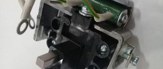
The pressure regulator is designed to automatically regulate pressure in the pneumatic system within the range of 0.65 0.8 MPa (6.5 8.0 KGS/SMZ), as well as to protect pneumatic drive units from contamination with oil and. excessive increase in pressure due to failure of the regulating device. The pressure regulator is connected by a pipeline directly to the compressor; attached with two bolts to the bracket.
pressure regulator
The atmospheric outlet of the regulator is directed downward so that the condensate released by the regulator does not fall on other parts of the car.
Repair of pressure regulator of the pneumatic system (“unloading”) of KamAZ, ZIL, KrAZ vehicles
Main malfunctions of the pressure regulator:
- stopping the air supply to the system
Air leakage from the pressure regulator itself:
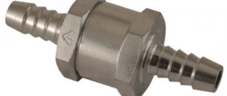
- if the pressure in the pneumatic system drops sharply at idle, the check valve is faulty.
- air comes out of the "pumping" valve.
The main malfunction of the regulator is the destruction of the rubber heads of the bypass valve:
- If, when pumping air, the regulator begins to operate at 2-4 atmospheres, then, most likely, this is caused by the destruction of the lower valve head, or, less often, the sealing ring of the narrow part of the piston.
- If the compressor pumps “all the way” and a hissing sound is heard from the top cover, this is a defect in the upper head of the bypass valve or the piston sealing collar.
Removing the pressure regulator
A similar pressure regulator is installed on KamAZ, ZIL and KrAZ vehicles. It is located on the right side of the frame behind the cab. For dismantling you need:
- Use a 22mm wrench to unscrew the two air lines
- wrench 13 – bolts securing the regulator to the frame
When the unloading is removed, clean it of dirt and secure it in a vice.
Disassembling the lower part of the pressure regulator
Using a 50mm wrench, unscrew the bottom cover.
Remove the filter and preload spring. The entire unloading valve mechanism is located in the cover. We check the condition of the o-ring of the unloader valve piston and replace it if necessary.
To do this, remove the retaining ring and remove the valve assembly with the seat.
- Use 10mm wrenches to unscrew the locknut
- Unscrew the second nut by inserting a suitable wrench into the hole in the valve rod.
The connection between the valve and the rod must be tight. To separate them, you need to apply force, but do not deform the valve. Eliminate shallow defects in the rubber surface of the valve by grinding the entire surface using a fine-grained abrasive wheel.
When connecting the valve to the rod, use sealant.
Disassembling the upper part of the pressure regulator
Using keys 17, loosen the lock nut, and with keys 12, unscrew the adjusting bolt.
Clamp the regulator in a vice. Using a 50mm wrench, unscrew and remove the spring with the thrust plate and guide assembly.
Grasp the piston from the inside and remove it.
Check the condition of the cuff. If necessary, replace it by installing it with the forked end down.
You can disassemble the check valve by unscrewing the support washer with narrow-nose pliers.
Remove the spring with the valve.
Using a 24mm wrench, unscrew the tire inflation device and remove it as an assembly.
If air comes out of the priming valve, replace the two o-rings.
Source
Not available:
| № | Part code | Name | Part Information |
| 1/60436/21 | Bolt M8-6ghx25 | Quantity for KamAZ 5320 2) KamAZ 53212 3) KamAZ 5410 4) KamAZ 54112 5) KamAZ 5511 6) KamAZ 55102 7) Model 14 Model 15 2 Fastener yes Material steel 80 (steel with tensile strength 784-980 ( 80-100) MPa (kg/mm2) Galvanized coating | Not available |
| 1/61008/11 | Nut M8x1.25-6N | Quantity for KamAZ 5320 2) KamAZ 53212 3) KamAZ 5410 4) KamAZ 54112 5) KamAZ 5511 6) KamAZ 55102 7) Model 14 Model 15 2 Fastener yes Material steel 50 (steel with tensile strength 490-784 ( 50-80) MPa (kg/mm2) Galvanized coating | Not available |
| 100-3512046-10 | Pusher | Quantity for KamAZ 5320 2) KamAZ 53212 3) KamAZ 5410 4) KamAZ 54112 5) KamAZ 5511 6) KamAZ 55102 7) Model 14 Model 15 1 Model 100 Group Brakes Subgroup Pressure regulator Serial part number 046 Additionally Not interchangeable with the part, previously released under the same number | Not available |
| 206-11600 | Pressure regulator | Quantity for KamAZ 5320 2) KamAZ 53212 3) KamAZ 5410 4) KamAZ 54112 5) KamAZ 5511 6) KamAZ 55102 7) Model 14 Model 15 1 | Not available |
| 4310-3512019 | Regulator mounting bracket | Quantity for KamAZ 5320 2) KamAZ 53212 3) KamAZ 5410 4) KamAZ 54112 5) KamAZ 5511 6) KamAZ 55102 7) Model 14 Model 15 1 Model 4310 Group Brakes Subgroup Pressure regulator Serial part number 019 | Not available |
| 5320-3512019 | bracket | Quantity for KamAZ 5320 2) KamAZ 53212 3) KamAZ 5410 4) KamAZ 54112 5) KamAZ 5511 6) KamAZ 55102 7) Model 14 Model 15 1 Model 5320 Group Brakes Subgroup Pressure regulator Serial part number 019 | Not available |
| 1/61008/11 | Nut M8x1.25-6N | Quantity for KamAZ 5320 2) KamAZ 53212 3) KamAZ 5410 4) KamAZ 54112 5) KamAZ 5511 6) KamAZ 55102 7) Model 14 Model 15 3 Fastener yes Material steel 50 (steel with tensile strength 490-784 ( 50-80) MPa (kg/mm2) Galvanized coating | Not available |
| 1/05196/01 | Flat washer 8x17 | Quantity for KamAZ 5320 2) KamAZ 53212 3) KamAZ 5410 4) KamAZ 54112 5) KamAZ 5511 6) KamAZ 55102 7) Model 14 Model 15 1 Fastener yes Material steel 40 (steel with tensile strength 333-490 ( 34-50) MPa (kg/mm2) Galvanized coating | Not available |
| 1/60436/21 | Bolt M8-6ghx25 | Quantity for KamAZ 5320 2) KamAZ 53212 3) KamAZ 5410 4) KamAZ 54112 5) KamAZ 5511 6) KamAZ 55102 7) Model 14 Model 15 1 Fastener yes Material steel 80 (steel with tensile strength 784-980 ( 80-100) MPa (kg/mm2) Galvanized coating | Not available |
| 1/60434/21 | Bolt M8-6gх20 | Quantity for KamAZ 5320 2) KamAZ 53212 3) KamAZ 5410 4) KamAZ 54112 5) KamAZ 5511 6) KamAZ 55102 7) Model 14 Model 15 2 Fastener yes Material steel 80 (steel with tensile strength 784-980 ( 80-100) MPa (kg/mm2) Galvanized coating | Not available |
| 100-3512057 | Washer | Quantity for KamAZ 5320 2) KamAZ 53212 3) KamAZ 5410 4) KamAZ 54112 5) KamAZ 5511 6) KamAZ 55102 7) Model 14 Model 15 1 Model 100 Group Brakes Subgroup Pressure regulator Serial part number 057 | Not available |
| 100-3512056 | Spring | Quantity for KamAZ 5320 2) KamAZ 53212 3) KamAZ 5410 4) KamAZ 54112 5) KamAZ 5511 6) KamAZ 55102 7) Model 14 Model 15 1 Model 100 Group Brakes Subgroup Pressure regulator Serial part number 056 | Not available |
| 100-3512054 | Valve assembly | Quantity for KamAZ 5320 2) KamAZ 53212 3) KamAZ 5410 4) KamAZ 54112 5) KamAZ 5511 6) KamAZ 55102 7) Model 14 Model 15 1 Model 100 Group Brakes Subgroup Pressure regulator Serial part number 054 | Not available |
| 100-3512099 | Tablet | Quantity for KamAZ 5320 2) KamAZ 53212 3) KamAZ 5410 4) KamAZ 54112 5) KamAZ 5511 6) KamAZ 55102 7) Model 14 Model 15 1 Model 100 Group Brakes Subgroup Pressure regulator Serial part number 099 | Not available |
| 304183 | Hollow rivet | Quantity for KamAZ 5320 2) KamAZ 53212 3) KamAZ 5410 4) KamAZ 54112 5) KamAZ 5511 6) KamAZ 55102 7) Model 14 Model 15 2 Coating without coating | Not available |
| 100-3512068 | Wing nut | Quantity for KamAZ 5320 2) KamAZ 53212 3) KamAZ 5410 4) KamAZ 54112 5) KamAZ 5511 6) KamAZ 55102 7) Model 14 Model 15 1 Model 100 Group Brakes Subgroup Pressure regulator Serial part number 068 | Not available |
| 100-3512067 | Ring sealing | Quantity for KamAZ 5320 2) KamAZ 53212 3) KamAZ 5410 4) KamAZ 54112 5) KamAZ 5511 6) KamAZ 55102 7) Model 14 Model 15 1 Model 100 Group Brakes Subgroup Pressure regulator Serial part number 067 | Not available |
| 100-3512069 | Ribbon | Quantity for KamAZ 5320 2) KamAZ 53212 3) KamAZ 5410 4) KamAZ 54112 5) KamAZ 5511 6) KamAZ 55102 7) Model 14 Model 15 1 Model 100 Group Brakes Subgroup Pressure regulator Serial part number 069 | Not available |
| 100-3512066 | Union | Quantity for KamAZ 5320 2) KamAZ 53212 3) KamAZ 5410 4) KamAZ 54112 5) KamAZ 5511 6) KamAZ 55102 7) Model 14 Model 15 1 Model 100 Group Brakes Subgroup Pressure regulator Serial part number 066 | Not available |
| 309793 | Ring sealing | Quantity for KamAZ 5320 2) KamAZ 53212 3) KamAZ 5410 4) KamAZ 54112 5) KamAZ 5511 6) KamAZ 55102 7) Model 14 Model 15 1 Coating without coating | Not available |
| 100-3512063 | Ring | Quantity for KamAZ 5320 2) KamAZ 53212 3) KamAZ 5410 4) KamAZ 54112 5) KamAZ 5511 6) KamAZ 55102 7) Model 14 Model 15 2 Model 100 Group Brakes Subgroup Pressure regulator Serial part number 063 | Not available |
| 100-3512062 | Valve body | Quantity for KamAZ 5320 2) KamAZ 53212 3) KamAZ 5410 4) KamAZ 54112 5) KamAZ 5511 6) KamAZ 55102 7) Model 14 Model 15 1 Model 100 Group Brakes Subgroup Pressure regulator Serial part number 062 | Not available |
| 258619 | Pin 4x30 | Quantity for KamAZ 5320 2) KamAZ 53212 3) KamAZ 5410 4) KamAZ 54112 5) KamAZ 5511 6) KamAZ 55102 7) Model 14 Model 15 1 Coating without coating | Not available |
| 100-3512060 | Spring | Quantity for KamAZ 5320 2) KamAZ 53212 3) KamAZ 5410 4) KamAZ 54112 5) KamAZ 5511 6) KamAZ 55102 7) Model 14 Model 15 1 Model 100 Group Brakes Subgroup Pressure regulator Serial part number 060 | Not available |
| 100-3512045 | Valve | Quantity for KamAZ 5320 2) KamAZ 53212 3) KamAZ 5410 4) KamAZ 54112 5) KamAZ 5511 6) KamAZ 55102 7) Model 14 Model 15 2 Model 100 Group Brakes Subgroup Pressure regulator Serial part number 045 | Not available |
| 100-3512042 | Valve body | Quantity for KamAZ 5320 2) KamAZ 53212 3) KamAZ 5410 4) KamAZ 54112 5) KamAZ 5511 6) KamAZ 55102 7) Model 14 Model 15 1 Model 100 Group Brakes Subgroup Pressure regulator Serial part number 042 | Not available |
| 100-3512040 | Piston | Quantity for KamAZ 5320 2) KamAZ 53212 3) KamAZ 5410 4) KamAZ 54112 5) KamAZ 5511 6) KamAZ 55102 7) Model 14 Model 15 1 Model 100 Group Brakes Subgroup Pressure regulator Serial part number 040 | Not available |
| 100-3512049 | Ring | Quantity for KamAZ 5320 2) KamAZ 53212 3) KamAZ 5410 4) KamAZ 54112 5) KamAZ 5511 6) KamAZ 55102 7) Model 14 Model 15 1 Model 100 Group Brakes Subgroup Pressure regulator Serial part number 049 | Not available |
| 100-3512050 | Cuff | Quantity for KamAZ 5320 2) KamAZ 53212 3) KamAZ 5410 4) KamAZ 54112 5) KamAZ 5511 6) KamAZ 55102 7) Model 14 Model 15 1 Model 100 Group Brakes Subgroup Pressure regulator Serial part number 050 | Not available |
| 309795 | Ring sealing | Quantity for KamAZ 5320 2) KamAZ 53212 3) KamAZ 5410 4) KamAZ 54112 5) KamAZ 5511 6) KamAZ 55102 7) Model 14 Model 15 1 Coating without coating | Not available |
| 100-3512023 | Locking screw | Quantity for KamAZ 5320 2) KamAZ 53212 3) KamAZ 5410 4) KamAZ 54112 5) KamAZ 5511 6) KamAZ 55102 7) Model 14 Model 15 1 Model 100 Group Brakes Subgroup Pressure regulator Serial part number 023 | Not available |
| 100-3512020 | Frame | Quantity for KamAZ 5320 2) KamAZ 53212 3) KamAZ 5410 4) KamAZ 54112 5) KamAZ 5511 6) KamAZ 55102 7) Model 14 Model 15 1 Model 100 Group Brakes Subgroup Pressure regulator Serial part number 020 | Not available |
| 100-3512022 | Plug pin | Quantity for KamAZ 5320 2) KamAZ 53212 3) KamAZ 5410 4) KamAZ 54112 5) KamAZ 5511 6) KamAZ 55102 7) Model 14 Model 15 1 Model 100 Group Brakes Subgroup Pressure regulator Serial part number 022 | Not available |
| 100-3512035 | Filter | Quantity for KamAZ 5320 2) KamAZ 53212 3) KamAZ 5410 4) KamAZ 54112 5) KamAZ 5511 6) KamAZ 55102 7) Model 14 Model 15 1 Model 100 Group Brakes Subgroup Pressure regulator Serial part number 035 | Not available |
| 100-3512025 | Ring | Quantity for KamAZ 5320 2) KamAZ 53212 3) KamAZ 5410 4) KamAZ 54112 5) KamAZ 5511 6) KamAZ 55102 7) Model 14 Model 15 1 Model 100 Group Brakes Subgroup Pressure regulator Serial part number 025 | Not available |
| 100-3512024 | Piston | Quantity for KamAZ 5320 2) KamAZ 53212 3) KamAZ 5410 4) KamAZ 54112 5) KamAZ 5511 6) KamAZ 55102 7) Model 14 Model 15 1 Model 100 Group Brakes Subgroup Pressure regulator Serial part number 024 | Not available |
| 489327 | Resistant ring | Quantity for KamAZ 5320 2) KamAZ 53212 3) KamAZ 5410 4) KamAZ 54112 5) KamAZ 5511 6) KamAZ 55102 7) Model 14 Model 15 1 Coating without coating | Not available |
| 100-3512026 | Valve thrust | Quantity for KamAZ 5320 2) KamAZ 53212 3) KamAZ 5410 4) KamAZ 54112 5) KamAZ 5511 6) KamAZ 55102 7) Model 14 Model 15 1 Model 100 Group Brakes Subgroup Pressure regulator Serial part number 026 | Not available |
| 302203 | Screw | Quantity for KamAZ 5320 2) KamAZ 53212 3) KamAZ 5410 4) KamAZ 54112 5) KamAZ 5511 6) KamAZ 55102 7) Model 14 Model 15 1 Coating without coating | Not available |
| 250612 | screw | Quantity for KamAZ 5320 2) KamAZ 53212 3) KamAZ 5410 4) KamAZ 54112 5) KamAZ 5511 6) KamAZ 55102 7) Model 14 Model 15 2 Coating without coating | Not available |
| 100-3512053 | Cap | Quantity for KamAZ 5320 2) KamAZ 53212 3) KamAZ 5410 4) KamAZ 54112 5) KamAZ 5511 6) KamAZ 55102 7) Model 14 Model 15 1 Model 100 Group Brakes Subgroup Pressure regulator Serial part number 053 | Not available |
| 100-3512052 | Top cover | Quantity for KamAZ 5320 2) KamAZ 53212 3) KamAZ 5410 4) KamAZ 54112 5) KamAZ 5511 6) KamAZ 55102 7) Model 14 Model 15 1 Model 100 Group Brakes Subgroup Pressure regulator Serial part number 052 | Not available |
| 100-3512016 | Spring plate | Quantity for KamAZ 5320 2) KamAZ 53212 3) KamAZ 5410 4) KamAZ 54112 5) KamAZ 5511 6) KamAZ 55102 7) Model 14 Model 15 1 Model 100 Group Brakes Subgroup Pressure regulator Serial part number 016 | Not available |
| 100-3512015 | Spring | Quantity for KamAZ 5320 2) KamAZ 53212 3) KamAZ 5410 4) KamAZ 54112 5) KamAZ 5511 6) KamAZ 55102 7) Model 14 Model 15 1 Model 100 Group Brakes Subgroup Pressure regulator Serial part number 015 | Not available |
| 100-3512043 | Spring guide assembly | Quantity for KamAZ 5320 2) KamAZ 53212 3) KamAZ 5410 4) KamAZ 54112 5) KamAZ 5511 6) KamAZ 55102 7) Model 14 Model 15 1 Model 100 Group Brakes Subgroup Pressure regulator Serial part number 043 | Not available |
| 100-3512048 | Resistant ring | Quantity for KamAZ 5320 2) KamAZ 53212 3) KamAZ 5410 4) KamAZ 54112 5) KamAZ 5511 6) KamAZ 55102 7) Model 14 Model 15 1 Model 100 Group Brakes Subgroup Pressure regulator Serial part number 048 | Not available |
| 100-3512044 | Guide | Quantity for KamAZ 5320 2) KamAZ 53212 3) KamAZ 5410 4) KamAZ 54112 5) KamAZ 5511 6) KamAZ 55102 7) Model 14 Model 15 1 Model 100 Group Brakes Subgroup Pressure regulator Serial part number 044 | Not available |
| 100-3512047 | Spring | Quantity for KamAZ 5320 2) KamAZ 53212 3) KamAZ 5410 4) KamAZ 54112 5) KamAZ 5511 6) KamAZ 55102 7) Model 14 Model 15 1 Model 100 Group Brakes Subgroup Pressure regulator Serial part number 047 | Not available |
| 100-3512046 | Pusher | Quantity for KamAZ 5320 2) KamAZ 53212 3) KamAZ 5410 4) KamAZ 54112 5) KamAZ 5511 6) KamAZ 55102 7) Model 14 Model 15 1 Model 100 Group Brakes Subgroup Pressure regulator Serial part number 046 | Not available |
| 100-3512027 | Spring plate | Quantity for KamAZ 5320 2) KamAZ 53212 3) KamAZ 5410 4) KamAZ 54112 5) KamAZ 5511 6) KamAZ 55102 7) Model 14 Model 15 1 Model 100 Group Brakes Subgroup Pressure regulator Serial part number 027 | Not available |
| 100-3512028 | Spring | Quantity for KamAZ 5320 2) KamAZ 53212 3) KamAZ 5410 4) KamAZ 54112 5) KamAZ 5511 6) KamAZ 55102 7) Model 14 Model 15 1 Model 100 Group Brakes Subgroup Pressure regulator Serial part number 028 | Not available |
| 100-3512029 | Washer | Quantity for KamAZ 5320 2) KamAZ 53212 3) KamAZ 5410 4) KamAZ 54112 5) KamAZ 5511 6) KamAZ 55102 7) Model 14 Model 15 1 Model 100 Group Brakes Subgroup Pressure regulator Serial part number 029 | Not available |
| 489304 | Resistant ring | Quantity for KamAZ 5320 2) KamAZ 53212 3) KamAZ 5410 4) KamAZ 54112 5) KamAZ 5511 6) KamAZ 55102 7) Model 14 Model 15 1 Coating without coating | Not available |
| 100-3512036 | Spring | Quantity for KamAZ 5320 2) KamAZ 53212 3) KamAZ 5410 4) KamAZ 54112 5) KamAZ 5511 6) KamAZ 55102 7) Model 14 Model 15 1 Model 100 Group Brakes Subgroup Pressure regulator Serial part number 036 | Not available |
| 489325 | Resistant ring | Quantity for KamAZ 5320 2) KamAZ 53212 3) KamAZ 5410 4) KamAZ 54112 5) KamAZ 5511 6) KamAZ 55102 7) Model 14 Model 15 1 Coating without coating | Not available |
| 100-3512030 | Valve seat | Quantity for KamAZ 5320 2) KamAZ 53212 3) KamAZ 5410 4) KamAZ 54112 5) KamAZ 5511 6) KamAZ 55102 7) Model 14 Model 15 1 Model 100 Group Brakes Subgroup Pressure regulator Serial part number 030 | Not available |
| 100-3512031 | Ring | Quantity for KamAZ 5320 2) KamAZ 53212 3) KamAZ 5410 4) KamAZ 54112 5) KamAZ 5511 6) KamAZ 55102 7) Model 14 Model 15 1 Model 100 Group Brakes Subgroup Pressure regulator Serial part number 031 | Not available |
| 100-3512033 | Ring sealing | Quantity for KamAZ 5320 2) KamAZ 53212 3) KamAZ 5410 4) KamAZ 54112 5) KamAZ 5511 6) KamAZ 55102 7) Model 14 Model 15 1 Model 100 Group Brakes Subgroup Pressure regulator Serial part number 033 | Not available |
| 100-3512032 | Valve body | Quantity for KamAZ 5320 2) KamAZ 53212 3) KamAZ 5410 4) KamAZ 54112 5) KamAZ 5511 6) KamAZ 55102 7) Model 14 Model 15 1 Model 100 Group Brakes Subgroup Pressure regulator Serial part number 032 | Not available |
| 305887 | Spring washer 6 | Quantity for KamAZ 5320 2) KamAZ 53212 3) KamAZ 5410 4) KamAZ 54112 5) KamAZ 5511 6) KamAZ 55102 7) Model 14 Model 15 1 Coating without coating | Not available |
| 250508 | Nut M6-6N | Quantity for KamAZ 5320 2) KamAZ 53212 3) KamAZ 5410 4) KamAZ 54112 5) KamAZ 5511 6) KamAZ 55102 7) Model 14 Model 15 2 Coating without coating | Not available |
| 252234 | Washer | Quantity for KamAZ 5320 2) KamAZ 53212 3) KamAZ 5410 4) KamAZ 54112 5) KamAZ 5511 6) KamAZ 55102 7) Model 14 Model 15 1 Coating without coating | Not available |
| 305906 | Washer | Quantity for KamAZ 5320 2) KamAZ 53212 3) KamAZ 5410 4) KamAZ 54112 5) KamAZ 5511 6) KamAZ 55102 7) Model 14 Model 15 1 Coating without coating | Not available |
| 100-3512037 | Ring | Quantity for KamAZ 5320 2) KamAZ 53212 3) KamAZ 5410 4) KamAZ 54112 5) KamAZ 5511 6) KamAZ 55102 7) Model 14 Model 15 1 Model 100 Group Brakes Subgroup Pressure regulator Serial part number 037 | Not available |
| 100-3512034 | Bottom cover | Quantity for KamAZ 5320 2) KamAZ 53212 3) KamAZ 5410 4) KamAZ 54112 5) KamAZ 5511 6) KamAZ 55102 7) Model 14 Model 15 1 Model 100 Group Brakes Subgroup Pressure regulator Serial part number 034 | Not available |
Pneumatic system pressure regulator
The pressure regulator is designed to automatically regulate pressure in the pneumatic system within the range of 0.65 0.8 MPa (6.5 8.0 KGS/SMZ), as well as to protect pneumatic drive units from contamination with oil and. excessive increase in pressure due to failure of the regulating device. The pressure regulator is connected by a pipeline directly to the compressor; attached with two bolts to the bracket.
The atmospheric outlet of the regulator is directed downward so that the condensate released by the regulator does not fall on other parts of the car.
Principle of operation
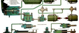
Compressed air from the compressor through terminal 1 of the regulator, filter 3, channel D and check valve 10 flows to terminal 111 and then into the air cylinders of the pneumatic drive. At the same time, through channel G, compressed air passes through cavity B under the balancing piston 9, which is acted upon by spring b. The outlet valve 4, connecting the cavity E above the unloading piston 12 with the environment through the outlet P, is open. The inlet valve 11, through which compressed air is supplied from the annular channel into the cavity E, is closed under the action of its spring in the same way as the unloading valve 2.
This state of the regulator corresponds to filling the air cylinders with compressed air from the compressor. When a certain pressure is reached in cavity B, the piston 9, overcoming the force of the spring 6, rises upward. Valve 4 closes under the action of the pusher, inlet valve 11 opens, and compressed air from the annular channel enters cavity E.
Kamaz brake pressure regulator
The pressure regulator automatically maintains the pressure in the pneumatic brake drive system within 620 ... 750 kPa, protects the pneumatic system from exceeding the maximum pressure (1000 ... 1350 kPa) and protects the pneumatic system from contamination.
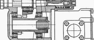
Fig. 1. Pressure regulator: a device, b position when pressure b in the system is less than 700...750 kPa, c position when the regulator valve is activated (pressure in the system 700...750 kPa), I input from the compressor, II, IV atmospheric outputs, III output to the pneumatic system; I unloading valve, 2 filter, 3 air bleeder plug, 4 exhaust valve, 5 balancing spring, 6 follower piston, 7, 8, II channels, 9 check valve, 10 inlet; valve, 12 unloading piston
| rice. 1 |
When the pressure in the system is less than 700... 750 kPa, compressed air from the compressor through input I of the regulator, filter 2, channel 11 is supplied to the ring channel 8 and then through check valve 9 and output III to the receivers of the vehicle's pneumatic system. At the same time, through channel 7, compressed air passes into cavity A under piston 6, which is loaded with a balancing spring 5. At the same time, the outlet valve 4, connecting cavity B above the unloading piston 12 with the atmosphere through outlet 11, is open, and the inlet valve 10, through which the compressed air is brought into cavity B, closed under the action of a spring. The unloading valve 1 is also closed under the action of the spring in the piston 12. Piston 12 is held in the upper position.
Upon reaching a pressure of 700 ... 750 kPa in cavity A, the piston 6, overcoming the force of the balancing spring 5, moves upward. In this case, the outlet valve 4 closes, the inlet valve 10 opens and compressed air from cavity A enters cavity B. The unloading valve 1 opens, passing the compressed air from the compressor through outlet IV into the atmosphere along with the condensate accumulated in the cavity. As a result, the pressure in channel 8 drops and check valve 9 closes. In this case, the compressor operates in unloaded mode without backpressure.
When the pressure decreases to 620... 650 kPa in port III, piston 6 moves downward under the action of spring 5, valve 10 closes, and outlet valve 4 opens, communicating cavity B with the atmosphere through port II. In this case, the unloading piston 12, under the action of the valve spring 1, takes the upper position, valve I is pressed against the seat, disconnecting input I from the atmosphere, and the compressor again pumps compressed air into the pneumatic system.
| rice. 2 |
If the regulator does not operate at a pressure of 700 ... 750 kPa, then unloading valve 1, when the pressure in the pneumatic system reaches 1000 ... 1350 kPa, opens, overcoming the resistance of the springs. In this case, terminal I communicates with the atmosphere, preventing the pressure from increasing above the specified value.
To connect special devices, the pressure regulator has an outlet closed with a screw plug 3. In addition, there is an air bleed valve for inflating tires, which is closed with a cap. When the tire inflation hose fitting is screwed on, the valve is recessed, opening the entrance to the brake system.
Before inflating the tires, the pressure in the receivers should be reduced to the pressure corresponding to turning on the regulator, since air cannot be bled during idling.
autoruk.ru
Pressure Regulator Maintenance
It consists of periodically checking its operation and cleaning the filter (during seasonal maintenance). Replacement of rubber valve seals (repair kit). Pressure adjustment.
If the limits of the adjustable air pressure in the pneumatic system do not correspond to 0.65 0.8 MPa (6.5 8.0 kgf/cm), (: using the adjusting bolt, you should adjust the pressure to the required limits. In order to remove the filter, you must unscrew bottom cover 1. After this, you need to rinse the filter in gasoline and clean the internal cavities of the regulator and cover.
WATCH THE VIDEO
Source
Repair of Kamaz pressure regulator
Secure the regulator in a vice with soft jaws to the boss of terminal 1 of housing 5.
It is forbidden to attach the regulator to the upper and lower parts of the housing 5, as this may lead to its deformation or destruction.
Unscrew the lock nut 7 and unscrew the adjusting screw 8, loosening the spring 6 of the balancing piston. Next, unscrew with a special 50 mm socket wrench mod. and 806.04.006 the top cover 15 and remove the spring b and the balancing piston 9 along with the inlet 11 and exhaust 4 valves, remove the sealing collar 20.
Unscrew the bottom cover 1 with the noise muffler. To remove the noise silencer, you need to unscrew it from the bottom cover and remove filter 3 with a spring and unloading piston 12 assembly. To disassemble the unloading piston 12, you need to remove two thrust rings 18 and 19 with round nose pliers.
To disassemble check valve 10, use round pliers to unscrew washer 22 and remove check valve with spring 21.
After disassembling the regulator parts, wash them with clean gasoline or acetone, dry them and carefully inspect them.
The surface of body parts must not contain cracks, hairs or other defects visible to the eye. Parts must be cleaned of rust and burnt marks. All rubber parts must be replaced with new ones.
The procedure for assembling the regulator is the reverse of disassembling. The threads on the lower 1 and upper 15 covers must be lubricated with graphite grease during assembly.
Adjusting and checking the pressure regulator after assembly. Install the pressure regulator on the test bench (see Fig. 2) and connect the device according to the diagram shown in Fig. 1), a. Then apply and release air at a pressure of 1.4 MPa three times into terminal I. In this case, terminal V must be plugged.
If the limits of the adjustable air pressure in outlet II do not correspond to 0.65...0.8 MPa, use the adjusting bolt 8 to adjust the pressure to the required limits. In this case, you should strive to achieve the upper pressure limits, since due to shrinkage of the springs during operation, the set pressure may decrease.
After adjustment, check the regulator switch-on and switch-off pressure three times, and then lock the adjusting bolt.
By installing adjusting washers of different thicknesses under the spring of the unloading valve, it is necessary to adjust the response pressure of unloading valve 2. To do this, you need to block the air passage to terminals I and II using a plug. Increase the pressure in port I three times and when the pressure reaches 1.0...135 MPa, the safety valve should open and air should escape through port III of the regulator. After adjustment, clear passage to terminal II.
To check the regulator for leaks, it is necessary to set a pressure of 0.05 MPa in terminals I and II, while checking the tightness of the inlet valve
II, piston cuff 9 and unloading valve 2. The tightness of the check valve 10 is checked by setting a pressure of 0.45 MPa in port II. When washing, the appearance of air bubbles is not allowed for 1 minute.
autoruk.ru
Design and principle of operation
The design of this mechanism includes such parts as:
- unloading piston and valve;
- air flow sampling plug;
- release type valve;
- spring mechanism;
- balancing device;
- adjusting screw;
- case;
- follower type piston;
- check valve;
- unloading mechanism saddle;
- cap;
- atmospheric findings;
- filter and pusher.
The flow of compressed air from the compressor system through the output of the control mechanism, filter elements and valves enters the receivers of the vehicle's pneumatic system.
The air passes through the channels under the piston part of the power unit, which is loaded by a spring balancing mechanism. At this time, the exhaust type valve connects the plane above the piston part.
Under the action of a spring mechanism, the inlet and discharge valves are closed, which allows the device that regulates the pressure level in the KamAZ system to be filled with air from the compressor.
Under the pressure of the air flow, the piston device overcomes the action of the spring and moves to the upper part of the system, the valve slams shut.
The compressed air lowers the piston mechanism back, and the valve opens again, and the compressed air flow passes through the terminals and penetrates into the environment along with the condensate accumulated in the working plane.
Description of the Kamaz pneumatic braking system
The basis for starting and stopping the air braking system is the circulation of compressed air. It is stored in special tanks. The circulation of compressed air is ensured by the operation of the compressor.
The brake operation diagram looks like this:
- Under conditions of increased pressure, a certain amount of air enters the compressor from the tank.
- After the brake system is activated, the operating torque is transmitted to the brake valve, which increases the pressure in the brake chambers.
- They are activated by a special lever, which is the key mechanism of the braking system.
- When the brake pedal is lowered, all parts return to their original position.
The backup brake works in a similar way. It is necessary to carry out maintenance of the brake system every 4 months.
Unloading valve with moisture separator KAMAZ
The condensate drain valve is poisoning.
KAMAZ brake system
The air dryer poisons air from the Volvo FSh FM emergency valve. Volvo Fh23 air dryer misses out
Where did the air come from?
Air leak from the brake valve KAMAZ ZIL PAZ MAZ KRAZ GAZ
Compressor connecting pipes
pressure regulator TOMEI TYPE-S for KAMAZ
Electrically controlled air dryer 13bar, with regulator and heating Volvo FH,FM 4324251010
How does an air brake system work?
Water separator assembly Euro-2
Also see:
- KAMAZ petal clutch diagram
- Box zf 151 KAMAZ 6520
- Terrion or KAMAZ
- Wiring diagram KAMAZ 4350
- KAMAZ anniversaries 2015
- KAMAZ engine packaging
- How to lubricate the king pin on a KAMAZ
- KAMAZ vankor dump trucks
- Dump truck with KMU on KAMAZ chassis
- Operating principle of the KAMAZ 5320 middle axle
- Kmu it 180 based on KAMAZ 43118
- KAMAZ equipment drive oil seal size
- Are there gasoline KAMAZ trucks?
- Why does the hydraulics on KAMAZ not hold up?
- A joke in a minibus about a KAMAZ driver
Home » News » Unloading valve with moisture separator KAMAZ
kamaz136.ru
Control and warning devices
The monitoring and warning device is a mechanism that serves to indicate a signal for increasing or decreasing pressure. The RDV adjustment is carried out using multi-colored lamps and a special signaling sound. This way the work of the main warning system is relieved. If there is a problem with its operation, it is enough to reset the settings and adjust the device again. Emergency alert works based on sensors installed in the brake system. If a problem occurs, the signal is immediately transmitted to the dashboard.
Performance indicators
The main operating parameters of the KamAZ 65115 and 5320 brake system are presented below:
- brake pad size is 400mm;
- the area of the brake seals is 6.3 square meters;
- The brake is controlled using a pedal;
- the brake chamber is type 24;
- the mechanism that controls pressure differences has two cylinders;
- the maximum air supply in the device is 220 liters per minute;
- number of air cylinders - 5 pieces;
- The volume of air cylinders is 120 liters.
KAMAZ unloading valve adjustment | KAMAZ
KAMAZ brake system
The condensate drain valve is poisoning.
Adjusting KAMAZ valves - New Method
Double-circuit safety valve KAMAZ
Air leak from the brake valve KAMAZ ZIL PAZ MAZ KRAZ GAZ
ZIL 5301 bull does not pump air into the circuit
Automatic brake force regulator KAMAZ
Bypass (unloading) valve ZIL
Body lift limit valve. Principle of operation. Repair. Service.
pressure regulator TOMEI TYPE-S for KAMAZ
Also see:
- KAMAZ engine frozen
- KAMAZ gearbox flange seal
- KAMAZ 65115 or 6520
- What is nar KAMAZ
- Crosspiece KAMAZ 6520 rear axle
- The fastest KAMAZ 4911
- KAMAZ engine fluid coupling drive
- Replacing the longitudinal rod on a KAMAZ video
- Maintenance of fuel equipment KAMAZ 740
- How to convert a KAMAZ gearbox to Yamz 238
- Mobile control center based on KAMAZ
- KAMAZ oil filter housing with heat exchanger
- Accident of VAZ 2115 and KAMAZ
- KAMAZ in ratings
- KAMAZ will stop on the move
Home » Clips » KAMAZ unloading valve adjustment
kamaz136.ru
How to adjust air pressure
In order to adjust the air pressure, it is necessary to install the vehicle on an inspection hole or a special platform for repair work.
Adjustment of the mechanism is carried out only when the power unit is turned off.
The whole process takes place in 3 stages: disassembly, adjustment and installation.
In order to dismantle the regulator, you need to unscrew the lock nut and turn out the adjusting screw. This will help loosen the counterbalance type piston springs. After this, use a special socket wrench to pull out the spring device, unscrew the protective cover and remove the sealing collar.
Malfunctions and repairs
Main malfunctions and repairs of the regulator:
- If air leaks from the atmospheric outlet, the valve body must be cleaned or the defective valve and O-ring must be replaced.
- The device has stopped switching the compressor to idle mode. This problem can be caused by a clogged channel, pinching of the piston, or damage to the cuff. It is recommended to clean the valve, conduct an external inspection of the cuff and, if necessary, replace it with a new one, and also update the piston.
- The regulator stopped switching the compressor to the mode of filling the system with air. This malfunction is associated with clogged atmospheric orifice and intake valve, damaged spring, worn O-ring, tight piston part and worn valves. It is necessary to conduct an external inspection of the entire system for damage and defects, and if necessary, replace failed spare parts.
- Air leakage through the outlet into the atmosphere can be eliminated by replacing the filter element.
- When there is no supply of compressed air flow to the brake system of a vehicle, it is necessary to clean the check valve from accumulated contaminants or replace it if worn.
- If there is a small shaft between the on- and off-pressure level of the regulating device, damaged cuffs and rings should be replaced, valves and seats should be inspected and cleaned.
All repair work is carried out only with the engine switched off.