Trucks produced by KamAZ PJSC use various models of gearboxes, which differ in their design and key operating parameters. Transmissions perform the function of transmitting torque in a car. During the operation of the mechanism, indicators such as the magnitude and direction of the torque change. The power unit is also disconnected from the transmission and power is taken for the drive.
Modern KamAZ vehicles are equipped with updated versions of mechanisms that are designed for engines with a torque of 1100 Nm. Gearbox 154 on KAMAZ vehicles is an improved version of the mechanisms, which have increased wear resistance, improved control and power.
The principle of the KAMAZ vehicle gearbox, description of features
The KamAZ vehicle is equipped with 2 types of gearboxes: those with five and ten stages. The design of the 10-speed gearbox includes a main 5-speed gearbox with gear ratios and a front 2-speed gearbox with gear ratios. Thanks to this divider, the car has as many as 10 forward and 2 reverse speeds.
The 5-speed gearbox includes:
- Gearbox housing, in which the primary, secondary and intermediate shafts assembled with gears, as well as synchronizers and bearings are mounted;
- Separate gear block for reverse gears;
- gear shift mechanism in a separate block at the top of the box;
- Gear divider attached to the front end of the gearbox housing 154 KAMAZ.
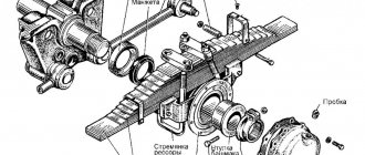
- Covers with sealing gaskets that cover the shaft bearings, while the outer race of the bearing is centering for the rear bearing cover of the input shaft.
- The outer race of the rear bearing 29 of the driven shaft is centering for the cover 27 of the rear bearing of the driven shaft, which is attached to the rear end of the crankcase of the KPP-154 Kamaz.
- A cuff with a boot installed in the rear part of the cover and having a working edge with a left notch.
- The right wall of the crankcase has a boring in the counters. The axis of the reverse gear block is pressed into this bore, securing it from falling out. The washer itself is screwed with a bolt with a drill, into which a plastic pin is inserted to seal the threaded connection and prevent lubricant leakage.
- On the right side of the crankcase there is a neck for filling oil into the gearbox. It is closed with a plug in which a dipstick is built in to control the level.
- Oil is poured into the gearbox through the neck located on the right wall of the crankcase. The drain plug, screwed into the bosses, is located at the bottom of the crankcase. It is equipped with a magnet that can capture metal particles in the oil.
- There are hatches on both sides of the crankcase for installing power take-offs. The hatches are closed with lids with sealing gaskets. GOST for hatches - 12323.
- Permissible power output of 22064.97 W (30 hp) from each hatch. Power take-off while the vehicle is moving is prohibited.
- The upper right part of the rear wall has a pocket for oil, into which it is thrown by the rotation of the gears. Drilling in the crankcase wall allows oil to pass from the pocket into the cavity of the rear cover of the driven shaft, thus lubricating the worm pair of the speedometer drive.
| 1st Gear | 2nd Gear | 3rd Gear | 4th Gear | 5th Gear | R | |
| P | 7,82 | 4,03 | 2,5 | 1,53 | 1,00 | 7,38 |
| N | 6,38 | 3,29 | 2,04 | 1,25 | 0,815 | 6,02 |
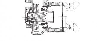
The primary shaft is mounted on 2 ball bearings. The front bearing is located in the crankshaft socket, the rear bearing is located in the bore of the front end of the gearbox housing. The drive shaft is supported by a retaining ring that protects it from shifting.
The input shaft is made together with the gear. The front part of the shaft goes into a cylindrical journal under the front ball bearing and has splines. The hubs of the driven clutch discs are mounted on the splines. The input shaft gear is helical and is constantly engaged with the intermediate shaft drive gear. It consists of an internal ring gear used to connect to the synchronizer carriage ring gear, and an internal cylindrical hole for installing the front roller bearing of the driven shaft.
The intermediate shaft is made together with the crowns of the gears of the 1st and 2nd gears and reverse gear. The 3rd and 4th gears and the intermediate shaft drive gear are pressed onto the front end of the shaft.
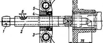
The driven shaft assembly with gears and synchronizers is installed coaxially with the drive shaft. A thrust ring with internal splines secures the 3rd and 4th gears. The arrangement of the ring splines is such that they are opposite the shaft splines. The ring is kept from turning by a spring-loaded key. Gear bearings receive oil supplied by the drive shaft oil pump through a drilled channel along the axis of the driven shaft. Inertial type synchronizers (2 pieces) are responsible for shockless gear shifting: 2nd, 3rd, 4th, 5th. The gear shift mechanism is mounted in the top cover of the box and is formed by:
- rods (3 pcs);
- shift forks (3 pcs);
- rod heads (2 pcs);
- clamps (3 pcs);
- fuses for 1st gear and reverse gear;
- rod locks. The rod lock is formed by 2 pairs of balls and a pin. The balls are located between the rods in the bushings, the pin is located in the hole in the middle rod between the balls.
The balls have such diameters that with a given inter-rod distance, if the rod moves from the middle position, they are able to exit the holes of the moving rod and enter the holes of the stationary rods. On the cover of the switching mechanism there is a support for the PP lever. On the right there is a set screw that secures the neutral position of the lever. In the working position, the screw must be turned out. The gear divider itself is formed:
- Spur gears;
- Drive and intermediate shafts;
- Synchronizer and PP mechanism with pneumatic control.
Metal spacers (02, 03 mm) installed between the back cover and the outer race of the ball bearing regulate the axial movement of the drive shaft. The involute splines for the finger synchronizer at the end of the shaft are divided by 2 grooves into 3 crowns. The teeth of the outer rings are thinner than those of the middle one, which makes it possible to create a “lock” to prevent the gears in the divider from switching off themselves. 2 roller bearings are the basis for the drive shaft gear rotating on them. Using an oil injection ring, oil is supplied through inclined drillings of the drive shaft into the internal cavity of the latter, after which it ends up in the channels of the drive and driven shafts of the main gearbox. The gear divider shift mechanism is located on the left side of the divider housing.
How to maintain a gearbox on KamAZ
Maintenance consists of:
- adjusting the gear shift drive;
- adjusting the gap in the divider activation valve;
- as well as periodic oil renewal.
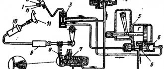
- Adjusting the gap between the end of the cover and the stroke limiter of the splitter valve rod: First, check the adjustment of the clutch release drive; adjustments are made as needed; The valve stem stop nuts, located on the pneumatic booster piston pusher, are unlocked and unscrewed. The control terminal of circuit IV of the auxiliary brake drive of the pneumatic brake drive is connected to a pressure gauge. The pressure in the circuit is brought to 7-7.5 kgf/cm; The clutch pedal is pressed all the way; the stop of the valve rod for switching on the divider is brought into contact with the valve rod limiter and moves towards the valve rod. The resulting gap between the end of the valve cover and the stem stop should be 0.2 - 0.3 mm. In this position, the valve stem stop is secured with nuts and locked with bend washers. If the pressure in the IV circuit of the auxiliary brake system drive has dropped to 6.2 kgf/cm2, the gap can be increased to 0.6 mm. Next, the valve stem and cover are closed with a rubber dust guard;
- Checking the oil. The oil filler plug is turned out, the indicator is wiped with a clean rag and inserted into the filler hole until the plug rests against the thread. No need to twist.
- The oil is changed at least once a year, but only if the car travels less than 90,000 km. If the car is involved in heavy work, then the number of times the oil is changed increases significantly. Therefore, when deciding on a replacement, you need to start not from the manufacturer’s recommendations, but from the operating conditions of a particular car. When replacing, the hot oil is drained through the drain holes (to do this, remove the plugs located in the lower part of the gearbox housings and in the lower part of the gear divider housing). The magnets of the drain plugs are cleaned of dirt and metal particles. The box and divider crankcases are washed with clean oil. Clean oil is poured into the gearbox, which must be cranked in neutral gear for 10 minutes; Then the oil is drained from the gearbox, the drain plugs are screwed in and TSp-1.5K lubricant is poured up to the upper mark of the level indicator. After this, you need to turn the gearbox back to neutral for 3-5 minutes. If after all the manipulations when measuring the level it turns out to be insufficient, then the oil needs to be added. The oil must be hot, because... the higher its temperature, the lower the viscosity.
Instructions
Now we suggest you find out how to start and in what sequence to correctly engage the gears on a KAMAZ gearbox. There are certain features in this process, and the procedure for changing gears differs from passenger cars.
Start of movement
You need to know how to change gears on a KamAZ. The start of movement on KamAZ should be done at a reduced speed
Please note that when driving away, the gear shift is carried out with the clutch disengaged. In KAMAZ gearboxes, the switching scheme is carried out in several stages, this is due to the peculiarities of increasing and decreasing speeds
How to turn on the speeds on KamAZ:
- The truck can drive quickly on different types of roads, but at the first stage, in accordance with the diagram, it is recommended to start driving in gear 1B.
- After this, 2V transmission is switched on.
- At the final stage of starting from a standstill, speed 3B is switched on.
In accordance with this traffic pattern, the vehicle starts at a reduced speed. That is, the shift lever on the box does not need to be touched until fourth gear. To start moving, you need to increase the crankshaft speed to about seven thousand revolutions (the author of the video lesson on how to switch gears on a KamAZ truck is Nikita Vagin).
Switching speeds
Now we’ll tell you how the gearbox on a KamAZ is switched when the car starts moving. When the car accelerates, the gear shift order on KamAZ is as follows - 4N-4V-5N. To activate the second speed, the crankshaft speed must increase to three thousand revolutions according to the tachometer. Please note that the operation of the crankshaft plays a major role. By changing gears correctly, you can achieve savings in fuel consumption. In this case, the most economical operation of the motor without downtime will be achieved.
Reverse
As for reverse, according to the diagram, to activate it, you need to set the switch to the lower left position. Activating reverse gear is not allowed while driving. To engage reverse, stop the vehicle completely and then perform the maneuver.
Removing the gearbox from the car and installing it
Gearbox removal includes
- The oil is drained from the crankcase;
- This is followed by tilting the cabin and removing the floor panels to gain access to the gearbox;
- Disconnecting the battery from the electrical circuit, disconnecting the terminal connecting the main switch to the frame;
- Disconnecting and pulling out the wire connecting the starter relay to the “+” terminal of the battery;
- The hose that serves as the connection between the engine intake manifold and the air cleaner connecting pipe is removed. To do this, you need to unscrew the nuts and pull out the bolts of the tie clamps;
- Disconnecting the plug connections of the tachometer, speedometer, trailer socket, brake light sensor, reversing lights, pressure drop indicator sensors in the receivers;
- Disconnecting the muffler mounting brackets to the splitter housing;
- Remove the pneumatic booster for the hydraulic clutch;
- The yoke flange of the propeller shaft of the middle axle is disconnected from the flange of the driven shaft of the gearbox by unscrewing the nuts of the fastening bolts, removing the spring washers and removing the bolts;
- The connecting hose of the ejector pipe is removed after loosening the tension bands;
- The air lines are disconnected from the trailer brake control valve with a 2-wire drive;
- Loosening the bolts securing the front supports of the power unit;
- Unscrewing the nuts of the rear engine mount bolts; removal of bolts;
- Unscrewing the bolts of the beam that serves to support the support to the frame;
- Unscrewing the bolts securing the gearbox support support to the transverse beam;
- Hanging the power unit by the gearbox eye bolts;
- Placing wooden stands under the front and rear halves of the 2nd frame cross member and lowering the power unit;
Important! The thickness of the supports should allow the rear support brackets to be 50 mm higher than the cushions.
- Unscrewing the pinch bolt of the front linkage lever of the gearbox control drive;
- Disconnecting the front linkage from the lever, removing the rubber boot, removing the ball and spring from the ball head of the lever tip;
- Disconnecting 3 bolts of the air divider control ducts from the block on the engine side, aligning the starter mounting bolts; Unscrewing the bolts securing the clutch or splitter housing to the engine flywheel housing by installing the chain grips of the lifting device behind the eye bolts on the gearbox;
- Removing the gearbox and installing it on the trolley.
Transmission Installation Plan
Important! Before connecting the gearbox to the engine, place 15 g of lubricant 158 into the cavity of the front bearing of the drive shaft located in the crankshaft bore;
- Lifting the gearbox and installing it in place with preliminary installation of the clutch release clutch, hose for supplying lubricant to the pressure bearing and release springs.
- Screwing in the bolts securing the divider housing to the engine flywheel housing.
- Screwing in the starter mounting bolts;
- Connecting the divider control pipelines to the connecting block.
- Connecting the front linkage to the lever with preliminary insertion of the ball and spring into the ball head of the lever;
- Screwing in the coupling bolt of the front linkage lever of the gear mechanism control drive;
- Regulation of the remote drive for controlling the gear shift mechanism;
- Hanging the power unit by the eye bolts of the gearbox;
- Screwing in the bolts securing the transmission support support to the transverse beam, after which the wooden blocks are removed from under the second transverse frame and the power unit is lowered onto the supports;
- Screwing in the bolts securing the support beam to the frame;
- Inserting bolts into the holes in the rear supports of the power unit, followed by tightening the self-locking nuts;
- Tightening the bolts securing the front supports of the power unit;
- Connecting air lines to the trailer brake control valve with a two-wire drive;
- Putting on the connecting hose of the ejector pipe and securing it with tightening tapes;
- Alignment of the holes in the yoke flange of the propeller shaft of the middle axle with the holes in the flange of the secondary shaft of the gearbox;
- Inserting bolts into holes, putting on spring washers, tightening nuts.
- Installation of a hydraulic clutch pneumatic booster;
- Attaching the muffler mounting bracket to the gearbox housing;
- Connection of plug connectors of a tachometer, tachograph, semi-trailer socket, brake light sensor, reversing lights, pressure drop indicator sensors in receivers;
- Connection of tachometer plug connectors;
- Putting on the hose connecting the engine intake pipe to the air cleaner connecting pipe;
- Putting on the clamps and securing the hose;
- Connecting the wire connecting the starter relay to the “+” terminal of the battery;
- Connecting the ground switch terminal to the vehicle frame (the terminal is located on the battery box);
- Connecting batteries to the vehicle's electrical circuit;
- Reimbursement of floor panels;
- Pouring oil into the gearbox housing;
- Cabin lowering;
- Check and, if necessary, adjust the free play of the clutch pedal.
Repair of gearbox divider for Kamaz vehicles
Possible breakdowns
- The ball bearings of the primary and secondary shafts are faulty;
- Overdrive gear roller bearings;
- The shaft and gear are damaged by the rollers;
- Gear teeth are broken;
- The fastening bolts of the secondary shaft support washer are loosened;
- To correct problems, the divider must be disassembled, the problem area identified, parts replaced, and the device reassembled.
Disassembly
- Removing the gear shift fork;
- Removing the synchronizer;
- Simultaneous removal of the release bearing fork and shaft;
- Unscrewing and removing the rear bearing cover of the input shaft;
- Removing the input shaft and bearing, after which it is necessary to align the cutout of the drive gear with the teeth of the intermediate shaft;
- Removing the intermediate shaft ball bearing cover. For this purpose there is a specially provided thread in the holes of the cover;
- Removing the bearing support washer and the roller bearing of the secondary shaft;
- Removing the bearing together with the glass;
- Knocking out the shaft from a ball bearing with a wooden block;
- Removing the bearing from the divider housing;
- Next, the input shaft is disassembled. It is disassembled by unscrewing the coupling nut with a left-hand thread, then the oil pressure washer, bearing with sleeve, drive gear and roller bearings are removed;
- If necessary, parts are replaced.
Material of manufacture
With this configuration of the body and suspension, the frame material plays a significant role in the safety and stability of the car. It is logical that strengthening the weak points of the body will make the vehicle stiffer and more stable on the road. But then the mass of the car will be critical, which will make it clumsy and very heavy.
When strengthening the frame, the weight of the “penny” and the load on all structural elements increases. That is why design engineers are trying to select the rational thickness of materials, taking into account the ratio of their dimensions and cross-section. The result is a fairly durable and not too heavy body.
Important Technical characteristics and design of the Ural-44202 car
To reduce weight and save on costs, elements that do not bear the load are made of thinner metal. The main parts have a thickness of about one millimeter, which corresponds to similar indicators for other cars of similar class.
View gallery