Installation device
Over all the years of serial production, it was possible to develop and launch the production of various modifications of the crane model KS-5363, which has a pneumatic wheel drive. They are distinguished by letter markings (from A to E).
In the basic configuration, the power plant is equipped with an electric motor, simultaneously with a two-stroke diesel unit, as well as two generators. The kinematics diagram of a lifting winch includes an electric motor connected through a coupling to a gearbox, a drum with a toothed ring, and brake pads.
The advantages of this crane are already visible from the documentation supplied with it:
- The performance of the device is not reduced due to operation with a diesel power generator.
- Maintenance of the installation is affordable and quite simple.
- It is allowed to use auxiliary devices and blocks during operation.
- The platform rotates when there is no load on the hook.
- Easy motion control.
- Spare parts for repair work are available.
Thanks to the sufficient distance between the wheelbases, the crane balances stably, ensuring the stability of the structure when performing lifting operations.
Installation, dismantling and transportation
Transport position The transfer of cranes from the working position to the transport position and back is carried out by its own mechanisms. Installation of jib extensions, transported separately from the crane, is carried out by an auxiliary crane.
Moving
It is allowed to move the cranes in the working position (together with the load). The load capacity should not exceed 25-30% of the nominal.
Cranes on pneumatic wheels in the transport position have dimensions exceeding the normative ones according to the “Rules of the Road”, which requires choosing a route for them. The movement of cranes and crane-excavators is carried out both under their own power and in tow.
Description of the unit
According to the passport, the KS-5363 crane is a diesel-electric design with a lifting capacity of 25 tons. It is equipped with two mechanism hooks for the main lift (25 tons), as well as auxiliary movement (5 tons). The crane also uses a grab with a pair of ropes and a bucket with a capacity of 2 cubic meters. m. Used on the crane to increase its load capacity, a multi-motor drive that powers an individual power generator set.
The speed of operation of the executive units is adjusted along the circuit from the generator to the engine by changing the supplied voltage to the main device that powers the motor.
When the crane is moving without a load, its cabin can be rotated. The installation provides a wide range for changing speeds in the movement system, not only in the working state, but also in the transport state. All equipment mechanisms are controlled using a mixed drive system.
The operator controls the main mechanisms using a push-button remote control and two command controllers. To perform gearbox shifts, control wheel turning when driving, outriggers, truck crane brake system, differential lock, pump-type hydraulics are present.
The differential or supports are controlled using the remote control on the running equipment itself; all other components are controlled directly from the operator’s cabin.
A gear pump ensures the functioning of hydraulics. Crane winches have rope handlers and spindle ends. The main fifteen-meter boom can be extended using 5 or 10 m inserts. The entire installation is equipped with a reliable tower-boom design.
The travel device has two drive axles with dual wheels. The frame has external telescopic supports, although the crane, with a small load, can do without them. Such special support attachments expand the dimensions of the base, increasing it by 0.8 m. The installation can be coupled with a coupling device to a tractor, which will move it at a speed not exceeding 20 km/h.
If it is necessary to transport equipment by rail, the boom along with the wheels is removed from it. To perform loading on a sixty-ton platform, another crane is used, which allows lifting a load of 25 tons.
Modifications
- KS-5363
- basic model, for temperate climates (from −40 °C to +40 °C). - KS-5363A
- the first modification. - KS-5363M
,
KS-5363AM
- military modifications. Manufactured to order by the USSR Ministry of Defense. Designed to work with both conventional and military discharge payloads, including strategic nuclear weapons. Each of the created cranes of these models underwent thorough acceptance by representatives of the Ministry of Defense before shipment. As of 2000, there were 63 such cranes in the Russian Navy, of which only 17 were working. - KS-5363B
is the second modification. The model is equipped with a UPG device, which increases the crane’s lifting capacity from 25 tons to 40 tons. It consists of an A-shaped mast, which, through ropes, holds an auxiliary 9-ton counterweight. This counterweight moves towards the platform when the crane is moved into transport position. The model has a number of other improvements (see below). - KS-5363V
- the third modification, development of
KS-5363B
, load capacity 36 tons. The model contains the UPG device. The additional counterweight in this model is held by means of ropes, which are attached to a 2-legged stand and to an outrigger frame attached to the platform. - KS-5363D
is the fourth model in the series, load capacity 36 tons. - KS-5363E
is the fifth model of the series, load capacity 36 tons. - KS-5363HL
- modification (northern), for work in northern regions with low temperatures. The design of the model is made of special. grades of steel with guaranteed impact strength at −70 °C, and the components of the crane mechanisms have been improved and are distinguished by increased reliability. - KS-5366
is the latest modification produced: lifting capacity 36 tons, hydraulic drive of the boom winch and turning mechanism.
This is interesting: We analyze the technical characteristics of the jib crane KS-55713 and all modifications in detail
Main installation parameters
Several tables summarize the main characteristics of the equipment.
| Minimum | Maximum | |
| Hook reach, if telescopic supports are not installed, m | 3,3 | 25,1 |
| Hook reach when installed on telescopic supports, m | 2,1 | 7,5 |
| Boom extension from installation, m | 2,5 | 15,9 |
| Probable rise | 13.7 m | 6.4 m |
| Speed when lifting weights, m/min | 7,5 | 9,0 |
| Load lowering speed, m/min | 0,7 | 9,0 |
| Cabin rotation, rpm | 0,1 | 1,3 |
| At what speed does the installation move, km/h | 3,0 | 20 |
| Support load | 324 kN | |
| Axial load | 174 kN | |
| Small turning radius, m | 10,3 | |
| Road elevation angle | 15° | |
| Diesel engine | 180 hp | |
| Electric motor | 166 kW | |
| Front wheel track | 2.4 m | |
| Rear wheel track | 2.4 m | |
| How much does the crane weigh? | 33 t | |
| Counterweight, t | 4,0 |
Installation parameters when moving:
| Cargo weight | 14 t |
| Percentage | 56 |
| Job site slope | 3 |
Basic arrow values:
| Length | 15 m |
| Maximum build-up | 30 m |
| Jib removal | 5–10 m |
| Grab volume | 2 cu. m |
Here you can download for comparison information on the characteristics of pneumatic wheeled and crawler cranes, where, among other things, the KS-5363 is described.
Load height characteristics of the crane
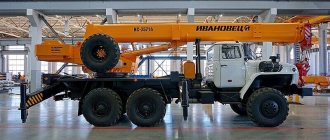
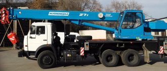
The KS-55721 "Galichanin" truck crane with a lifting capacity of 36 tons is designed for loading and unloading, construction and installation work at dispersed sites. The crane installation is mounted on the chassis of a KamAZ-6540 vehicle with an 8×4 wheel arrangement. The use of a four-axle base chassis, as well as the concept of a removable counterweight implemented in the design of the truck crane, in the transport position between the first and second axles, provides the crane as a vehicle with optimal distribution of axle loads, without exceeding the permissible values for public roads.
The drive of the crane installation is hydraulic, powered by two axial piston hydraulic pumps. Power take-off to the pumps is made from the base chassis engine through the gearbox and additional power take-off box. The crane mechanisms have an individual drive with independent control from hydraulic motors and hydraulic cylinders. The winches for the mechanisms for lifting loads and turning the platform are of the planetary type. The hydraulic system of the crane installation ensures smooth control of all mechanisms with a wide range of speed control for working operations, and provides the ability to combine several working operations.
A distinctive feature of this model of truck crane is the idea of using additional removable counterweights, which was first implemented in the domestic crane industry, providing excellent load characteristics of the crane with optimal distribution of axial loads of the base chassis.
The crane counterweight consists of two parts: stationary and removable. The removable part of the counterweight weighing two tons in the transport position is placed on the fixed frame of the crane installation between the first and second axles of the base chassis. To install the removable part of the counterweight on the rotating platform of the truck crane, a special mechanism is used on the frame, eliminating the use of additional lifting equipment and human resources for this purpose.
Important All-terrain vehicles for hunting and fishing: wheeled and tracked vehicles for the most inaccessible places
A four-section telescopic boom with a length of 9.6 - 29.1 m ensures the compactness and maneuverability of the truck crane when moving, a wide area and a large lifting height during operation. To increase the lifting height of the hook and the size of the boom space, the truck crane can be equipped with a lattice jib 9 m long, which is attached to the boom head. In the transport position, the jib is rotated and secured to the side of the boom. The transfer of the jib from the transport position to the working position is carried out manually without the use of additional lifting equipment.
The ability to telescope boom sections with a load on a hook allows the truck crane to perform special tasks during installation, install loads in hard-to-reach places, and carry them among mounted structures.
Safe operation of the crane is ensured by a complex of instruments and devices, including a microprocessor load limiter with digital indication of parameters on the display in the driver’s cabin. The load limiter can operate in the coordinate protection mode of the crane, has a built-in telemetric memory unit (“black box”) and a built-in module for protecting the crane from dangerous voltage (MZON) to ensure safe operation of the truck crane near power lines.
| Crane specifications echo $name; ?> | |
| Maximum load capacity, t | 36 |
| Maximum load moment, tm | 108,8 |
| Telescopic boom length, m | 9,6…29,1 |
| Jib length, m | 9,0 |
| Maximum lifting height, m | |
| with main boom | 29,4 |
| with main boom and jib | 38,7 |
| Maximum depth of lowering the hook with the boom 9.6 m at a reach of 5 m, m | 12 |
| Maximum telescopic load, t | 6 |
| Hook lifting (lowering) speed, m/min | |
| nominal (with a load weighing up to 36 tons) | 5 |
| increased (with load up to 14 tons) | 10…20 |
| maximum (pulley multiplicity 1) | 35,6 |
| Landing speed, m/min | 0,15 |
| Time of full departure change, s | 60 |
| Boom telescoping time, s | 80 |
| Turntable rotation speed, rpm | 0,2…1,0 |
| Basic chassis | KamAZ-6540 |
| Maximum crane travel speed, km/h | up to 80 |
| Overcome slope of the track | 25° |
| Crane weight in transport position, t | |
| with main boom | 30,3 |
| with main boom and jib | 31,0 |
| Support contour size, mm | |
| along the chassis axis | 4 600 |
| across the chassis axis with the outrigger beams extended (retracted) | 5 800 (2 270) |
| Overall dimensions in transport position, mm | |
| length | 12 000 |
| width | 2 500 |
| height | 3 750 |
| Operating temperature, °C | ±40 |
Hydraulic system
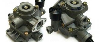
The hydraulic drive of such a crane model as KS-5363 is entirely based on the operation of the pumping device model NSh-32E. The system also includes a hydraulic tank, cylinders and other components necessary for reliable operation.
Operation is ensured by supplying oil of a certain viscosity from the hydraulic tank to the pump. This pump directs the fluid to the cylinders, bypassing the distribution stage of the movement. Due to the presence of valves in the cylinders, the required pressure is maintained there. The piston moves under the influence of oil.
Chassis
The movement mechanism is provided by generating torque in several bridges. Each axle (of which there are two in the cart) rotates 4 wheels. To increase the load-carrying characteristics, outrigger supports with a hydraulic drive are additionally installed. Thanks to them, the dimensions of the equipment expand, reaching a parameter of 5 m.
The rear axle ensures rotation of all wheels. To transport equipment, they use the towing method or loading a crane onto a railway platform. For the first option, the installation is folded; when loading, it is necessary to additionally remove the wheels with the boom.
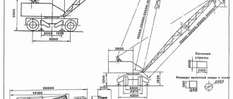
Description of the tower crane KS-5363 and the technological process in which it participates
Crane KS - 5363 in working (top) and stowed (bottom) positions
For the course design, a full-rotating crane on a pneumatic wheeled chassis with a lifting capacity of 30 tons KB - 5363 was chosen. This crane is equipped with outriggers that reduce the specific pressure of the chassis on the ground, thereby increasing the load capacity of the crane and extending the service life of the chassis, since there is no excess pressure in the wheel tires air. The crane has a fairly well-equipped control cabin, which has excellent visibility; these factors make it possible to minimize the psychological load on the crane operator and his fatigue.
The crane is equipped with a combined diesel-electric drive and electro-hydraulic drive, which ensures high smoothness of all movements. The crane is intended for the installation of prefabricated reinforced concrete and steel structures, technological equipment of industrial facilities, for the installation of road structures, as well as for loading and unloading operations.
The crane's main hoist winch has a conventional single-engine design, in which the engine is connected via a coupling to a three-stage gearbox, the output end of which is connected to the drum. The clutch connecting the engine and the gearbox has a friction surface, facilitating the operation of the brake, which keeps the load and the hook suspension from moving arbitrarily when the engine is braked.
Main lift winch diagram
Kinematic diagram of the main lift winch
This drive requires deep speed control, which is why it was chosen for course design.
Lifting equipment
Basic as well as additional accessories are provided as structures for the crane modification KS-5363. The main components include the following devices:
- fifteen-meter boom supplied in the kit;
- main rope of extended boom;
- auxiliary rope.
The replacement devices supplied with the unit are as follows:
- replaceable booms that can be added, allowing you to extend the main structure by 5 or 15 m;
- The reach of the replacement boom is possible within the range of 5.5–26.3 m.
A boom with a lattice extension is also installed. Its reach can reach 17.1 m.
Scheme KS-5363
- The length of the main lattice boom is 15 m; it can be extended 2 times with special inserts 5 or 10 m long.
It is possible to attach a rigid or shunting jib with a length of 8 or 15 m.
Basic equipment
The main equipment of the KS-5363 is a lattice-type rigid boom and ropes.
Boom length=15m.
Main rope: ø=21mm, l=140m;
auxiliary rope: ø=21mm, l=95m.
Replacement equipment
Replacement equipment includes:
rigid extended booms; jib devices; tower-boom elements. Tower height=20-30m.
The length of the extended replaceable boom and boom with jib on the main and auxiliary suspension = 20-30 m, in the tower-boom device = 10 m.
Transportation of KS-5363 over long distances is carried out in 2 ways:
- Towing with a special tractor. When towing, the mechanism must be folded, speed≤20km/h.
- On a railway platform (60t) – the wheels and boom are removed.
Pneumatic wheel cranes perfectly combine excellent quality with a reasonable price. Long-term experience indicates that the funds invested in such machines are quickly returned.
Management organization
Each piece of equipment operates through a mechanical system, adjustable electrical or hydraulic equipment. The first option is implemented by a remote control that ensures the operation of the wheels, outriggers, brake system, and power take-off.
The electric motor ensures the operation of the winch. Its strength reserve is transferred to the drive axles of the main chassis in the form of an all-welded frame. The hydraulic system provides all lifting operations of the installation.
Driver's cab
The front area of the self-propelled crane cabin is equipped with a dashboard. It contains a pressure gauge with a thermometer, a voltmeter with an ammeter, various levers, and also switches. On the sides of this panel there are controllers with visual instruments displaying power take-off. The steering control of the structure is also located here.
The cabin is equipped with an electric heater, it is possible to warm up the windows in cold weather, there are windshield wipers and a fan. The operator's chair is adjustable both in height and in the angle of reclining of the backrest. Since the front (together with the sides) wall is partially glazed, the operator is provided with an all-round view, allowing him to observe the operation of the equipment and all components.
The installation contains a load limiter of the OGP-1 brand. To prevent the lifting height of the hook from exceeding the permissible parameters, a spindle limit switch is used. It is triggered when the winch shaft rotates at a set angle.
With a gear, such a switch is connected directly to the winch itself. The limiter must be adjusted when repairs are made to the working equipment or load rope. To prevent the possibility of the loaded boom tilting, the equipment must be provided with a telescopic stop.
Electrical equipment
The power plant of the described self-propelled crane includes:
- Diesel YaMZ-236.
- Starter.
- Two generators producing direct current.
To provide power to the electric motors that transmit rotation to the movement mechanism simultaneously with the winches, a DK-303B generator is used, producing a final power of 50 kW. The auxiliary generator of the P-62 model powers the control circuit equipment, rotary device, and lighting. Its power (nameplate) is 11 kW.
At the same time, the turning mechanism is able to be powered by the main generator. The installation is equipped with only DC electric motors, which have maximum mechanical strength and are guaranteed to be able to withstand overloads.
Thanks to the presence of a resistor, it is possible to regulate the speed of the electric motor that controls the rotating mechanism. For other motors, the rotation speed is changed by changing the voltage on the main generator. This is done according to the instructions describing the operating rules of the installation.
The operator controls all crane mechanisms using controllers.
To start the boom winch, you need to press the button while simultaneously moving the handle of such a controller to ensure the boom is raised or lowered. You can brake it by moving the handle to neutral while simultaneously pressing the stop button. Rotations are also carried out by a controller and a switch that sends a command to the auxiliary generator.
To increase the accuracy of load supply during equipment installation, a main generator with a winch controller is used. In order to turn to the right, the handle is placed in the same position as when ascending, in order to turn left - as when descending. Moving both handles to the Neutral position stops the mechanism. It is prohibited to combine movements when adjusting speeds.
The movement mechanism is controlled in the same way. The engine is started by pressing the “Start” button while smoothly moving the controller handle between positions 1 and 5 to increase speed. Depending on the state of the handle in the “Right” or “Left” positions, the crane moves forward/backward.
Video: in the KS-5363 crane.
To increase the speed of movement, you need to perform the following operations: put the controller handle in the neutral position, then set the gearshift knob to the next speed, press “Start”, and then smoothly move the controller handle to where you want to move.
To perform electric braking while the unit is moving, the controller handle must be placed in the neutral position, then press the “Brake” button one by one while holding it. When you stop pressing the button, the braking system automatically stops being locked.
Stopping for a short period of time is achieved by moving the handle to the neutral position, pressing “Stop”, and then turning on the brake belonging to the unit’s movement mechanism. When parking for a long time, be sure to use the parking brake.