Crane MKG-25BR: cargo and technical characteristics
MKG-25BR cranes are high-performance crawler-type special installation equipment. The machines have virtually unlimited capabilities in terms of loading and unloading any objects weighing up to 25 tons.
Special equipment adequately withstands high loads and operation in difficult conditions. Cranes are produced in various modifications, some of which are no longer produced due to the discrepancy between economic feasibility and accuracy.
Scope of application
MKG-25BR are successfully used in various spheres of the national economy: loading and unloading operations, installation of reinforced concrete structures, construction of buildings, bridges, road surfaces. Thanks to its technical data, the equipment is indispensable for servicing logistics complexes and assembling technological equipment.
For more than 60 years, the MKG-25BR crawler crane has been used in industry, as well as in mining mines. Thanks to its technical versatility, high functionality and ease of maintenance, the machine is extremely popular among private and public organizations and businessmen who work in the construction industry.
The technique is used to clear away rubble after all kinds of disasters and damage to structures. It is for this reason that the MKG-25BR is in demand among Emergency Situations Ministry workers.
Technical characteristics of special equipment
The technical characteristics of the MKG-25BR crane are ideal for operation in complex construction and industrial areas, in special mine conditions.
| Load capacity | 25 t, with an additional hook – 5.2 t |
| Boom Reach | 4.2–11.9 m |
| Reach of additional jib | 5.1–13.5 m |
| Lifting height | 12 m |
| Basic equipment | Equipped with a non-retractable boom |
| Replacement equipment | Supplemented with a non-retractable boom with 4 modifications |
| Load lifting speed | 0.9–6 m/min |
| Load lowering speed | 11.1–16.8 m/min |
| Boom height | 12.5 m |
| Turntable swing speed | 0.6 rpm |
| Maximum travel speed on crawler tracks | 0.8 km/h |
| Clearance | 45 cm |
| Dimensions of the running platform | 4.7x3.21 m |
| Ground pressure | 0.8 kgf/cm² |
| Track width | 625 mm |
| Weight | 39 t |
| Engine | D-180 |
| Maximum power | 108 l. With. |
| Drive unit | Electric |
Design and use of equipment
MKG-25BR cranes have a whole list of design features. Special installation equipment copes with numerous tasks, including combined ones:
Load characteristics of the MKG-25BR crane
- installation;
- loading and unloading.
The cranes do not cause problems during maintenance and operation; they have a standard set of technical devices and are easy to operate. The length of the main boom is increased by adding lattice inserts. MKG-25BR are equipped with a rigid fixed jib, which adds 5 m to the total boom height.
The cranes are capable of moving loads weighing up to 25 tons. Thanks to the tracked chassis, the machines can easily move in unprepared areas.
The multifunctional cabin has reliable thermal insulation and rust protection. Inside, it is finished with materials that absorb vibrations and noise well, which creates comfortable working conditions. Other advantages include a large glass area and an autonomous heater.
The MKG-25BR crawler crane is characterized by high maneuverability and smooth movement, which is ensured by a special suspension and the ability to turn around 360⁰ on the spot. These qualities are especially important when working in cramped and hard-to-reach areas. For convenience and fuel economy, the cranes operate using diesel units or an electrical network with a power of 380 W.
Cabin MGK-25BR
Additional technical specifications
Dimensions MKG-25BR
The technical features of the MKG-25BR allow it to be used in a variety of climatic zones, in particular in the equatorial and arctic. The machines are quickly installed without requiring large labor and financial costs.
A modern security system monitors the condition of moving mechanisms, protecting them from overheating, overload, loss of pressure and other technical problems. Special sensors record the load and position of the boom, which prevents proximity to high-voltage wires.
Equipment can be transported in different ways: by rail or road. In the latter case, using a tractor. If necessary, the cranes move independently at a speed of 0.8 km/h. Spare parts from similar Russian-made machines are suitable for repairing equipment.
Operation of the MKG-25 BR crane is possible at contrasting temperatures. The equipment can be deployed along any trajectory and does not require preliminary preparation of the site surface before work.
Related video: Crawler crane MKG-25BR
specnavigator.ru
Machines with a lifting capacity from 5 to 20 g with a short boom equipped with a hook or grab are used for loading and unloading work with piece cargo, bulk and small-piece materials; machines with extended booms and jib are intended for construction and installation work in industrial and residential construction. Machines with a lifting capacity of 40-50 g with extended booms and jib are intended mainly for the installation of industrial enterprises, hydraulic structures, as well as large-panel (fully prefabricated) residential and civil buildings (up to 7-8 floors in height).
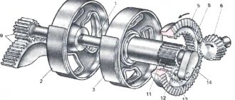
A crawler crane (excavator crane) consists of the following main parts: – a rotating platform on which the crane mechanisms, power unit, and portal A-frame where the boom is mounted are mounted; – a cabin installed on a turntable; – rotary support device; – support-running device; – working equipment, including normal and extended booms with jibs, hooks and grabs.
Cranes have four working movements: lifting the load, turning the boom, moving the crane, raising and lowering the boom with the load.
The operation of the cranes is controlled by one driver, with the exception of the E-2001 crane, which is serviced by a driver and his assistant.
The E-257 excavator crane (Fig. 62) is diesel, with a lifting capacity of up to 5 g, equipped with a hook and a grab with a capacity of 0.35 m3.
In Fig. 63 shows kinematic diagrams of the crane mechanisms. The boom-lifting winch is made with a worm gear.
All mechanisms are driven by a D-35 diesel engine via chain and gear transmissions.
Braking of the load when lowering can be done by mechanical brakes and a running engine; lowering the boom - with a running engine through reversing and rotating mechanisms. The running gear of the crane is made in the form of two multi-mounted crawler bogies.
The crane operates with booms 6.5 long; 7.5 and 12 m. The 6.5 m boom is used both when operating an excavator and when operating a crane. The 12 m long boom is obtained by extending the 7.5 m boom using inserts.
Rice. 62. Crawler crane-excavator E-257
The control of all mechanisms is lever, with a mechanical servo device.
On the crane it is possible to combine the following two working movements: lifting or lowering the load with rotation of the boom; lifting or lowering a load with raising or lowering the boom; lifting or lowering a load with the movement of a crane.
The reversible device of the transmission shaft is designed to service the mechanisms of boom rotation, crane movement and boom lifting, as a result of which the combination of their work is excluded.
The excavator crane is transported by rail without disassembly with the boom removed.
The rotating platform with mechanisms and replaceable working equipment are unified with the E-258 excavator crane.
The E-303 excavator crane (Fig. 64) is diesel, with a lifting capacity of up to 5 tons, equipped with a hook and a grab with a capacity of 0.35 m3.
The crane can be used for loading and unloading and installation work. When equipped with a 15-gauge boom, the crane can mount one- and two-story houses with elements weighing up to 2 tons.
In Fig. 65 shows kinematic diagrams of the crane mechanisms. All mechanisms are driven by a D-36 diesel engine. The crane has three drums, cargo, grab and boom. Braking of the load during descent can be done by mechanical brakes and a running engine; braking when lowering the boom - with the engine running. The running gear of the crane is made in the form of two multi-support crawler trolleys, the drive of which is carried out from a vertical shaft through a bevel gear and a horizontal shaft consisting of three parts connected by claw couplings.
Rice. 63. Kinematic diagrams of the mechanisms of the E-257 excavator crane 1 - cargo drum; 2 — grab drum; 3—boom lifting drum; 4 — main reverse; 5 — reverse of the cargo drum
The main equipment of the crane is a lattice boom with a length of 7.5 m, with which the rated lifting capacity of the crane is 5 tons.
To work with a grab, this boom can be extended to 12 m using inserts 1.5 and 3 m long, the crane’s lifting capacity is reduced to 3 g; when extended to 15 m, the crane’s lifting capacity is reduced to 2 g. Mounting boom length 15 m with a 5 m jib allows lifting a load weighing up to 1 t.
Rice. 64. Crawler crane-excavator E-303
To install a lattice boom or grab, it is necessary to remove the front strut and reposition the ropes.
The crane control is mixed: pneumatic and lever. The pneumatic system controls all friction clutches, brakes, reverse and tracks. The control of auxiliary mechanisms: gear shifting, engine clutch, boom winch clutch, rotary mechanism brake is lever-based.
On the crane it is possible to combine the following two working movements: a) lifting (or lowering) the load and rotating the crane platform; b) lifting (or lowering) the load with raising (or lowering) the boom in accordance with the load characteristics of the crane; c) lifting (or lowering) the load and moving the crane.
Rice. 65. Kinematic diagrams of the mechanisms of the E-303 excavator crane 1 - engine; 2 — cargo drum; 3 — grab drum; 4 — boom-lifting drum; 5 - ring gear of the turning mechanism
Combining the movements of changing the boom reach with rotation of the platform or movement of the crane, as well as rotation of the crane platform with its movement, is impossible due to the presence of a common reversing device for these mechanisms and a common drive gear, which alternately turns on the rotation or movement mechanisms. The crane is transported by rail in assembled form, but with the arrow removed.
Rice. 66. Crawler crane-excavator E-505 (E-505A and E-652) a - graph of the crane-excavator E-652
Excavator cranes E-505A, E-505 and E-651 (Fig. 66) are diesel, with a lifting capacity of up to 10 tons, equipped with hooks and grabs with a capacity of 0.5 m.
The kinematic diagram of the mechanisms of such excavator cranes is shown in Fig. 67.
On the shaft of the main winch there is a cargo drum 1 and a drum for working with a grab or with an auxiliary hook 2.
Rice. 67. Kinematic diagrams of the mechanisms of excavator cranes E-504A, E-505A, E-651, E-652 1—load drum; 2 — grab drum; 3 — boom-lifting drum; 4 — main reverse; 5—reverse of the main winch; 6 — free-flow coupling; 7 - friction clutch; 8 — ratchet device; 9 — engine coupling
All mechanisms are driven from a KDM-46 (KDM-100) diesel engine through chain and gear drives or from an AC electric motor powered from an external network. The excavator crane with an electric motor was produced under the E-504 and E-504A brands. Braking of the load during descent can be done by mechanical brakes and a running engine; lowering the boom - on the brake with the crane device turned off; the descent speed is limited by an overrunning clutch connected to the drum by a chain drive. When lifting stops, the boom is held in place by the pawl and the differential brake.
The running gear of the crane is two multi-support crawler trolleys.
Rice. 68. Crawler crane-excavator OM-201 (OM-202)
The crane is equipped with a main boom 10 m long and an extended one (using inserts) up to 18 m, which is additionally equipped with a jib 5 m long. The control of the crane mechanisms is hydraulic and lever. On a crane it is possible to combine the following two working movements: lifting (or lowering) a load with rotation of the crane platform; lifting (or lowering) a load with raising or lowering the boom; lifting (or lowering) a load with the movement of a crane; raising (or lowering) the boom with rotation of the crane platform; raising (or lowering) the boom with the movement of the crane.
The reversible device of the transmission shaft is intended to serve the mechanisms of rotation of the platform and movement of the crane, as a result of which the combination of these movements is excluded.
When transporting an excavator crane by rail, only the lattice boom is removed from it.
The OM-201 (OM-202) excavator crane (Fig. 68) is diesel, with a lifting capacity of up to 10 g, equipped with a hook and a grab with a capacity of 0.5 l3. Kinematic diagrams of the crane mechanisms are shown in Fig. 69.
The crane is driven by a KDM-46 (KDM-100) diesel engine, to which a two-speed gearbox is connected. In this case, the main winch shaft can rotate at one speed, obtained from turning on the first pair of gears of the gearbox.
The boom winch has a worm gearbox, which receives rotation from the turning mechanism using a small gear.
The reversing device is common to the jib winch and the mechanisms for turning and moving the crane, which prevents their combined operation. Braking of the load during descent can be done by mechanical brakes and a running engine. The boom lowers while the engine is running.
The running gear of the crane is multi-support crawler trolleys.
The crane has two booms 10 and 13 g long.
When working with a hook and a grab, a counterweight weighing 1.13 tons is placed in a hollow counterweight plate. When working with a grab, the crane's lifting capacity varies from 2.5 to 10 tons when equipped with a boom length of 10 g and from 1.7 to 8 g when equipped with boom 13 m long.
Mechanism control is lever.
When transported by rail, the lattice booms are removed, which allows them to fit into the 1-T gauge. In terms of the design of some components, productivity, speed of working movements and some other indicators, the OM-201 and OM-202 excavator cranes are inferior to the E-505 and E-505A excavator cranes.
The E-652 excavator crane (see Fig. 66) is diesel, with a lifting capacity of up to 10 tons, equipped with a hook and a grab with a capacity of 0.5 l3. For a kinematic diagram of the crane mechanisms, see Fig. 67.
All mechanisms are driven by a KDM-46 (KDM-100) diesel engine.
On the shaft of the main winch there are two drums - the load of the main hook 1 and the load of the auxiliary (on the jib) hook, also known as the grab 2. When working with a crane, an additional counterweight of 2.5 tons is installed on the machine.
Loads weighing from 7.6 to 10 tons are lifted using a triple pulley; weighing up to 7.5 g - on a double pulley.
The load is braked by the mechanical brake of the main winch and the running engine; braking when lowering the boom - working; engine.
The running gear of the crane is two multi-support crawler trolleys.
The crane has a main boom 10 m long and an extended boom 18 m long. A hook or grab is suspended from the 10-meter boom; the extended boom can be equipped with a 5-meter jib.
The control of the main mechanisms is pneumatic, auxiliary - lever.
On the crane it is possible to combine two working movements: lifting (lowering) the load with rotation of the crane platform; lifting (lowering) the load with lifting (lowering) the boom and lifting (lowering) the load with the movement of the crane.
When moving by self-propelled vehicles, the following are allowed: lateral roll up to 15° (with the main boom), slope or rise up to 22°.
The crane is transported by rail without disassembly with the boom removed and fits into the 1-T dimension.
Rice. 69. Kinematic diagrams of the mechanisms of the OM-202 excavator crane 1 - KDM-46 engine; 2 ~ cargo drum; 3 — grab drum; 4 - boom lifting drum
A modification of the E-652 excavator crane is the E-653 excavator crane, which differs only in the chassis (wider tracks).
The E-754 excavator crane (Fig. 70) is diesel, with a lifting capacity of up to 15 tons, equipped with a hook and a grab with a capacity of 0.75 l3. Kinematic diagrams of its mechanisms are shown in Fig. 71.
Rice. 70. Crawler crane-excavator E-754 (E-753)
On the shaft of the main winch there are cargo and grab drums. The boom winch is made with a worm gear.
All mechanisms are driven by a KDM-46 diesel engine or an AC electric motor powered from an external network; The crane with an electric motor was produced under the E-753 brand.
The load is slowed down during descent by mechanical brakes and a running engine, and the boom is lowered by a running engine. The running gear of the crane is two multi-support crawler trolleys.
Rice. 72. Crawler crane-excavator E-801
The crane has a main boom 11 m long and an extended boom 15 m long. The crane mechanisms are controlled by levers. On the crane it is possible to combine two working movements: – lifting (or lowering) the load with rotation of the crane platform; – lifting (or lowering) a load with raising or lowering the boom; – lifting (or lowering) a load with the movement of a crane.
The reversible device of the transmission shaft is intended for servicing the mechanisms: rotation, movement and boom winch, as a result of which the combination of their work is excluded.
When transporting a crane by rail, only the lattice boom is removed from it.
The E-801 excavator crane (Fig. 72) is diesel, with a lifting capacity of up to 15 tons, equipped with a hook and a grab with a capacity of 0.75 l3.
The crane is intended for the installation of steel and reinforced concrete structures of buildings and structures, including large-panel and large-block residential buildings up to four floors high with elements weighing up to 2 tons.
Kinematic diagrams of the crane mechanisms are shown in Fig. 73.
All mechanisms are driven by a KDM-46 (KDM-100) diesel engine.
On the shaft of the main winch there are boom-lifting and grab drums, as well as a sprocket of the chain drive of the anti-overrunning device for lowering the boom in engine mode. A load drum is placed on a separate shaft. Braking of the load during descent can be done by mechanical brakes and a running engine; braking the lowering of the boom - with the engine running.
Unlike the E-505 and E-1004 excavator cranes, the E-801 excavator crane does not reverse the movement of the vertical shaft, but the rotation of the horizontal shaft with reverse spur gears. The rotation speed is changed through an additional (accelerating) gear, consisting of internal gears.
The running gear of the crane is two multi-support crawler trolleys with a chain drive to the drive wheels.
The crane has a main boom length of 11 m, which can be extended to 20 m with two extensions of 3 and 6 lengths. The control of the main mechanisms of the crane is pneumatic, auxiliary - lever; it is performed from a remote control located in the driver’s cab. The cabin is isolated from the engine room and is heated in winter.
Unlike the E-754 excavator crane, the E-801 excavator crane has two speeds of platform rotation and crane movement, obtained from a two-speed gearbox.
The kinematic diagram of the machine mechanisms ensures that the movements of changing the boom reach are combined with the movements of turning the platform or with the movement of the crane. This feature allows you to effectively use the E-801 excavator crane for the installation of structures.
The machine is transported by rail on a platform with a lifting capacity of 40 g, without disassembly, with the boom removed and fits into the 1-T clearance.
Excavator cranes E-1004, E-1004A (Fig. 74) are diesel, with a lifting capacity of up to 15 tons, equipped with hooks and grabs with a capacity of 1.5 mg. The kinematic diagram of the machine mechanisms is shown in Fig. 75. The difference between the kinematic diagram of the E-1004 crane and the kinematic diagram of the E-1004A crane is only in the hydraulic pump drive.
On the shaft of the main winch there is a cargo drum and sprockets of the reversing mechanism. To operate as a grab, replaceable drum parts are installed instead of sprockets.
All mechanisms are driven by gear transmissions from a KDM-46 diesel engine or from an AC electric motor powered from an external network; Cranes with an electric motor are produced under the brands E-1003 and E-1003A.
Rice. 73. Kinematic diagrams of the mechanisms of the crane-excavator E-801 1 - diesel KDM-46 (KDM-100); 2 - friction clutch; 3 speed switch; 4 - ratchet device; 5 — lifting drum; 6 — cargo drum; 7 — grab drum; 8 - stopper
Braking of the load during descent can be done by mechanical brakes and a running engine; lowering the boom - with the engine running.
The undercarriage of the machine is two multi-support crawler bogies. The excavator crane has a main boom with a length of 13 g and an extended boom with a length of 23 g. The control of the main mechanisms is hydraulic, auxiliary - lever.
Rice. 74. Crawler excavator crane E-1004 (E-1003, E-1004A, E-1003A, E-1252 and E-1251)
Rice. 75. Kinematic diagrams of the mechanisms of excavator cranes E-1004A (E-1003A, E-1251 and E-1252) 1 - cargo drum; 2 — grab drum; 3 — boom-lifting drum; 4 — main reverse; 5 - engine; 6 — reverse of the main winch For E-1003A excavator cranes; E-1004A; E-1252 gears with t = 2.5 are missing
On excavator cranes it is possible to combine the following two working movements: a) lifting (lowering) the load with rotation of the crane platform; b) lifting (lowering) the load with raising or lowering the boom; c) lifting (lowering) the load with the movement of the crane.
The reversible device of the transmission shaft is designed to service the mechanisms of platform rotation, crane movement and boom lifting, as a result of which the combination of their work is excluded.
When transporting the crane by rail (two platforms with a lifting capacity of 20 and 40 g, size 1-T), the lattice boom is partially disassembled and removed.
The E-1252 excavator crane (see Fig. 74) is diesel, with a lifting capacity of up to 20 tons, equipped with a hook and a grab with a capacity of 1.5 l3.
The machine is driven by a 2D6 diesel engine with a power of 120 hp. With. or from an asynchronous electric motor with a squirrel-cage rotor MA-146-2/4 with a power of 85 kW, powered from an external network. The excavator crane driven by an electric motor is brand E-1251; it is completely unified with the E-1252 vehicle. For the kinematic diagram of its mechanisms, see Fig. 75.
On the main winch shaft there is a cargo threaded drum and a reversing mechanism sprocket. To work with the grab, replaceable parts of the drums are installed instead of the sprocket. Loads weighing 10-20 tons are lifted on a triple pulley, and weighing up to 9 g - on a double pulley.
Braking of the load during descent can be done by mechanical brakes of the main winch and a running engine; braking when lowering the boom - with the engine running.
The undercarriage of the machine is two multi-support crawler bogies.
The excavator crane has a main boom 12.5 m long and three extended ones (using replaceable inserts) - 15, 20 and 25 m.
The control of the main mechanisms is hydraulic, auxiliary - lever.
The machine can combine two working movements in the same way as in the E-1003 and E-1004 excavator cranes. The crane is transported by rail on two platforms with a lifting capacity of 20 and 40 tons without disassembly with the boom removed (extended). To fit into the 1-T size, the side walls of the body are removed from the turntable and the two-legged stand is lowered.
The E-1254 excavator crane (Fig. 76) is diesel, with a lifting capacity of 20 tons, equipped with a hook and a grab with a capacity of 1.5 l3.
The excavator crane is designed for the installation of steel and prefabricated reinforced concrete structures of industrial, residential and rural buildings, including large-block and large-panel residential buildings with a height of 3-5 floors from elements weighing up to 5 g.
The kinematic diagram of the excavator crane mechanisms is shown in Fig. 77.
All mechanisms are driven by a 2D6 diesel engine. On the main winch shaft there is a cargo threaded drum and a reversing mechanism sprocket. To work with the grab, replaceable parts of the drums are installed instead of the sprocket.
Loads weighing from 10 to 20 g are lifted on a triple pulley, and weights up to 10 g are lifted on a double pulley, which increases the lifting speed by 1.5-2 times.
Braking of the load during descent can be done by mechanical brakes of the main winch and a running engine; braking when lowering the boom - with the engine running.
The running gear of the crane is two multi-support crawler trolleys.
The excavator crane has a main boom of 12.5 m, which can be extended to 20, 25 and 30 m using replaceable sections. Booms of 25 and 30 m are equipped with a 5-meter jib. The crane has replaceable equipment - a tower with a boom, equipped with main and additional hooks.
The control of the main mechanisms is hydraulic, auxiliary - lever.
Rice. 76. Crawler excavator crane E-1254 a - with a normal1 boom; b - with an extended boom; c — tower equipment
On the crane it is possible to combine two working movements, just like in the E-1003 and E-1004 excavator cranes.
The machine is transported by rail (two platforms with a lifting capacity of 20 tons) without disassembly with the extended boom removed. To fit into the 1-T size, the side walls of the body are removed and the two-legged stand is lowered.
The SKG-25 (S K G-30) crane (Fig. 78) is diesel-electric, with a lifting capacity of up to 25 tons, equipped with main and auxiliary hooks. The crane is intended for the installation of prefabricated reinforced concrete and steel structures of single- and multi-bay light and medium-sized industrial workshops and for hydraulic engineering construction.
Rice. 77. Kinematic diagrams of the mechanisms of the E-1254 excavator crane 1—engine; 2 - vane pump; 3 - multi-speed gearbox; 4 — reverse of the boom-lifting winch; 5 — boom-lifting drum; 6—cargo drum; 7—grab drum
Kinematic diagrams of the crane mechanisms are shown in Fig. 79. The SKG-25 crane uses a rotating platform with a power plant, mechanisms and a cabin - from the SK-25 railway crane and tracks - from the E-2001 excavator crane; the booms of the SKG-25 crane are unified with the booms of the SK-25 crane.
On the platform there is a diesel-electric station DSS-3, consisting of a diesel engine KDM-46 (KDM-100) and an alternating current generator SG-60/6, a boom winch, main and auxiliary hoists (on a jib), a control panel and a cabin. At the end of the turntable, ballast made of cast iron plates is placed. All mechanisms are driven by individual crane electric motors with phase rotors receiving
Rice. 78. Crawler diesel-electric crane SKG-25 (SKG-ZO) a - graph of lifting capacity and lifting height for the SKG-ZO crane; o” - lifting height lifting capacity chart for the SKG-25 crane
The numbers in brackets refer to the SKG tap - a turn from its own power plant or from an external network via a flexible cable and a ring current collector.
Rice. 79. Kinematic diagrams of crane mechanisms SKG-25 (SKG-30) a - power plant; b—boom winch; c — auxiliary lift winch; g - rotation mechanism; d — main lift winch; e—mechanisms for moving the crane; 1 — diesel l KDM-46; 2—generator SG-60/16; 3 - drive wheel
The main lift winch is controlled using a command controller, and other mechanisms are controlled using cam controllers.
The load and boom are braked by a running engine.
The rotating platform does not have a central axle: vertical loads are perceived by a multi-roller rolling circle and four reverse rollers, two of which are balancing. Horizontal forces are perceived by four vertical rollers resting on the side surface of the rolling circle.
The running gear of the crane consists of two tracks and a frame, connected to each other using four axle shafts. The crane's movement mechanisms are mounted on cantilever platforms fixed in the end walls of the frame and connected to the drive wheels of the tracks located diagonally.
A design feature of the crane is a load limiter, which takes into account the effect on the crane of static and dynamic loads, as well as loads from slope and wind.
The crane is equipped with a normal boom 15 m long, which can be extended to 20 and 25 m using inserts. The 25 m boom is equipped with a 5-meter jib. The crane is designed to operate with booms of 30, 36 and 45 g in length. The 30 m long boom is made up of standard sections of 7.5 and 5 g.
The crane has four working movements: lifting and lowering the load, changing the reach of the boom with the load, rotating the platform, moving the crane with a suspended load. When the crane is operating, it is possible to combine any three of its movements.
It is allowed to move the crane with a load, but combining movements is not allowed.
The design of the SKG-25 crane ensures its self-loading onto railway platforms using a special device in the form of inventory beams, an auxiliary lifting winch and jacking devices mounted on the running frame and turntable.
Before dismantling, the crane is installed on sleepers, a sleeper cage is laid out under the platform, the auxiliary hoist winch rope is stored on the anchor block, and inventory beams are laid that connect the running frame of the crane and the platform.
On the railway platform, where the crane turntable is installed, the decking is partially removed and special beams are fixed. The crane boom is lowered to a horizontal position. After this, the support circle is disconnected from the running frame, the rotating platform is installed using jack rollers on the inventory beams, the auxiliary lift winch is turned on, and the rotating part of the crane is moved onto the platform. Next, the support circle is fixed to the frame of the railway platform using two special beams and bolts, after which the jack rollers are lifted and the inventory beams are removed. Then the fixed rotating part is used as a crane for loading the undercarriage components: caterpillar and running frame.
To speed up and facilitate these operations, the crane chassis is equipped with four jacks (located in twos on the cantilever platforms of the movement mechanisms) and four tension screws, hinged in the track frames and passing through the nuts of the chassis frame. The running frame is hung on jacks, after which the track frames along with the axle shafts are disconnected from it using screws. After dismantling is completed, the tracks, chassis frame, two boom sections and jib are loaded onto the platforms. The entire crane is placed on three platforms: two 20 g (running frame and boom sections with jib) and one 60 t (slewing part and track frames).
Rice. 80. Crawler excavator cranes E-2001 (E-2002 and E-2006)
The set of auxiliary mounting devices used during installation, dismantling and loading of the crane consists of two inventory beams weighing 1.5 tons and a set of fastening beams and bolts weighing 0.65 tons. This set is an inventory of one or more cranes, if the latter belong to one installation organization and are used at concentrated sites.
Based on the SKG-25 crane, the SKG-30 crane was produced, which has the highest lifting capacity of 30 tons (see Fig. 78). The design of the rotating platform in the crane has been changed, the layout of the mechanisms has been improved, as a result of which the weight of the SKH-30 crane has been reduced by 2 tons compared to the SKH-25 crane.
Rice. 81. Kinematic diagrams of the mechanisms of excavator cranes E-2001 (E-2002) 1 - main hook lifting drum; 2 — auxiliary hook lifting drum; 3 — boom-lifting drum; 4 — main reverse; 5 — reverse of the main winch; 6 — engine coupling
Rice. 82. Kinematic diagrams of the mechanisms of the crane-excavator E-2006 1 - diesel; 2 - compressor; 3—multi-speed gearbox; 4 — reverse of the boom-lifting drum; 5 — boom-lifting drum; 6 — cargo drum; 7 - grab drum
The E-2001 excavator crane (Fig. 80) is electric, with a lifting capacity of up to 50 tons, equipped with a hook. The 2D12 diesel driven excavator crane is produced under the E-2002 brand.
Kinematic diagrams of the crane mechanisms are shown in Fig. 81.
On the shaft of the main winch there is a drum for lifting with the main hook and a drum for working with the auxiliary hook (when the boom is equipped with a jib boom). The boom winch has a worm gear.
All mechanisms are driven by an AC electric motor, powered from an external network via a cable or from a 2D12 diesel engine.
Braking of the load during descent can be done by mechanical brakes and a running engine; lowering the boom - with the engine running. The running gear of the crane is two multi-support crawler trolleys. The excavator crane has a main boom with a length of 15 g and two extended ones (using inserts of 5 and 10 g) up to 30 and 40 m.
All mechanisms are controlled pneumatically by a compressor driven by a separate electric motor.
On an excavator crane it is possible to combine two working movements: a) lifting (or lowering) a load with rotating the platform; b) lifting (or lowering) a load with raising or lowering the boom; c) lifting (or lowering) a load with the movement of a crane.
The reversible device of the transmission shaft is designed to service the mechanisms of platform rotation, crane movement and boom winch, as a result of which the combination of corresponding movements is excluded.
The car is transported by rail disassembled (on two platforms with a carrying capacity of 50 tons each).
The E-2006 crane (see Fig. 80) is diesel, with a lifting capacity of up to 50 tons, is equipped with a hook and is intended for the installation of heavy steel and reinforced concrete structures in industrial and hydraulic engineering.
The crane is based on the E-2002 excavator crane with improved (in relation to installation requirements) speed characteristics for lifting loads and turning the crane platform.
The kinematic diagram of the crane mechanisms is shown in Fig. 82.
The crane is driven by a 2D12 diesel engine, to which a two-speed gearbox is connected, switched by levers. By using it, changing the number of shaft revolutions within the range of 1,500–750 rpm, you can additionally change the speed of rotation of the cargo drum and the crane platform rotation mechanism. The drive of the boom hoisting winch is made independent, which ensures the combination of the movement of changing the boom reach with the movements of lifting (lowering) the load, rotating the platform and moving the crane (without load).
Braking of the load during descent can be done by mechanical brakes and a running engine; braking the lowering of the boom - with the engine running. The crane, in addition to the main boom with a length of 15 m, has two extended ones with a length of 30 and 40 m.
The control of the main mechanisms is pneumatic, auxiliary - lever.
The reversing device is designed for mechanisms for turning the crane platform and its movement; therefore, combining the operation of these mechanisms is impossible.
For transportation by rail (two platforms with a lifting capacity of 50 tons each) and on trailers, the crane is disassembled.
2) Technical characteristics, information on performance, installation and dismantling of cranes
Technical characteristics of crawler cranes V-E excavators
Table 90
Technical characteristics of the installation crawler crane SKG-25 (SKG-ZO)
Table 91
The performance indicators of individual cranes are given in table. 92.
Table 92 Productivity of crawler excavator cranes in cycles
Indicators of labor intensity and cost of installation and dismantling of cranes and the composition of teams of workers to perform these works are given in Table. 93 and 94.
Table 93 Labor intensity and cost of installation and dismantling of crawler cranes and excavator cranes
Note. The scope of work includes installation and removal of the crane boom.
Table 94 Composition of teams of workers for installation and dismantling of crawler cranes and excavator cranes
Rice. 83. Schedule of changes in the cost of machine shifts for crawler cranes and excavator cranes 1-E-257, E-303, OM-202, E-505A, E-552, E 753; 2-E-751, E-8E1; 3 —E-10EZ A, E-1004A, E-1251, E-1252, E-1254; 4 -E-2001, E-2006, SKG-25 (SKG-30)
Information on the vehicles required for transporting crawler cranes and excavator cranes is given in table. 95.
Table 95 Vehicles required for transporting crawler cranes and excavator cranes
In Fig. 83 shows a graph of changes in the cost of machine shifts for crawler cranes and excavator cranes.
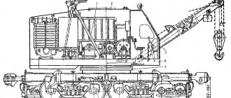
Crawler crane MKG-25BR (MKG-25.01)
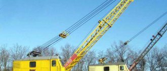
The crawler, full-rotating, diesel-electric crane MKG-25 BR, MKG-25.01A is one of the most mobile and convenient cranes with a lifting capacity of 25 tons. Widely used for any installation, loading and unloading and construction work.
Thanks to a large number of different replaceable boom equipment, it is capable of performing the entire cycle of construction and installation work from the zero cycle to the final construction of a ground-based facility. Widely used in bridge construction.
The MKG - 25 BR, MKG-25.01A crane is capable of operating both from an external power supply with a voltage of 380 V and from a built-in diesel generator set, which allows solving a wide range of needs as an additional source of electricity.
The crane's main boom of 13.5 meters can be extended to 33.5 meters using inserts and, at any boom length, can be equipped with a fixed jib 5 meters long, with a lifting capacity of 5 tons.
If necessary, tower-boom equipment can be installed on the crane, which will increase the lifting height to 47 meters and the reach to 21.5 meters.
| Technical characteristics of the MKG-25BR crane | |
| Maximum main lift capacity | 25 tons |
| Maximum auxiliary lift capacity | 5 tons |
| Maximum lift height | 47 m |
| Maximum reach | 21.5 m |
| Maximum boom length | 33.5 m |
| — Female goose | 5 m |
| — Shunting jib | 10, 15, 20 m |
| Crane weight | 38.9 - 40.1 tons (depending on version) |
| Ground pressure (during operation) | 0.1 MPa |
| Undercarriage width | 4300 mm |
| Power plant power | 60 kW |
| Net | 380 V, 50 Hz |
Load-height characteristics of the MKG-25 BR, MKG-25.01A crawler crane in tower-jib version.
Load-height characteristics of the MKG-25 BR, MKG-25.01A crawler crane in the jib version with a rigid jib of 5 meters.
arenda-krana32.ru
Classification
Depending on the design features, tracked vehicles are divided into two large groups.
The first of them is represented by boom self-propelled equipment with a lifting capacity ranging from 40 to 160 tons. Its individual mechanisms are equipped with their own drive.
The second group includes excavator cranes that have group drive mechanisms. They have a lower carrying capacity - up to 50 tons.
Crane excavator
Tracked modifications are divided into:
- for assembly ones - they are used in the construction of large objects due to their high load capacity;
- self-propelled - distinguished by the ability to carry and locally target large structures;
- boom - equipped with a counterweight that allows you to lift heavy loads to significant heights.
Crawler cranes also differ in boom design, which can be:
- straight;
- telescopic;
- curved.
Hitachi SCX3500-3 crawler crane
Rent of a crawler crane MKG-25 up to 40 tons in St. Petersburg
The MKG-25BR crane is a self-propelled jib assembly full-rotating diesel-electric crawler crane, which is successfully used in the field of installation, construction and loading work. Due to its reliability and wide range of work, the crane takes part in the entire stage of construction and installation.
Technical characteristics of the MKG - 25 BR crane
- Maximum lifting capacity of the main lift - 25 tons
- The maximum lifting capacity of the auxiliary lift is 5 tons.
- Maximum lifting height - 47 m
- Maximum reach - 21.5 m
- Maximum boom length - 33.5 m
- rigid jib - 5 m
- shunting jib - 10, 15, 20 m
- Crane weight - 38.9 - 40.1 tons (depending on version)
- Ground pressure (during operation) - 0.1 MPa
- Chassis width - 4300 mm
- Power plant power - 60 kW
- Network - 380 V, 50 Hz
The MKG-25BR is equipped with a safety system that does not allow the crane to be overloaded, thereby increasing its service life and preventing the risks of unexpected breakdowns, including damage in confined spaces.
Chief Mechanic Department
(rental of lifting equipment)
+7-921-933-47-79
The crane is unpretentious and can adapt to different zones. In addition, it does not require a specially prepared site to perform the work and is able to move steadily with a load in various conditions, reaching speeds of up to 0.8 km/h.
The crane can be powered either from an external power source, thereby ensuring efficiency and relative noiselessness, which is important in urban environments, or from its own 60 kW diesel generator set.
The operator's cabin is thermally insulated and protected from external noise that prevents the operator from concentrating on work. The controls are standard and familiar to most operators who work with similar cranes.
Advantages of the MKG-25 crawler crane
Crawler crane rental prices
Services of the MKG-25 crawler crane:
- Load capacity. The maximum lifting capacity of the MKG crane is 25 tons.
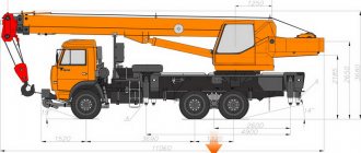
- Dimensions. The transport dimensions of the chassis without shooting equipment are 5450 mm in length, 3200/4300 mm in width, 3825 mm in height and 700 mm in track width, taking into account the 400 mm ground clearance. It is not surprising that with such dimensions, the operating weight of the crane with the main boom is 40 tons. Therefore, the crawler crane can only move at a speed not exceeding 1.1 km/h with a maximum lifting angle of 15 degrees.
- Boom equipment. The length of the crane's main boom is 13.5 meters and can be increased to 33.5 meters by connecting lattice inserts. The smallest boom radius is 4.2 meters, the largest, taking into account the main and extended booms, is 21.5 m. The maximum lifting height ranges from 13.5 - 33/47 meters. The highest load lifting speed is 7.3 m/min, while the lowest is 0.4 m/min. Similar indicators exist for another work operation associated with lowering the load; the maximum speed is 7 m/min, the minimum speed is the same 0.4 m/min, while the average speed is 3.5 m/min.
- Rotating platform. A movable platform that rotates 360 degrees eliminates all accusations that the crane is clumsy and sluggish. The rotation speed of the platform is not so high: from 0.3 to 1 rpm.
- Electrical equipment. The installed D-108-1 engine with a power of 108 hp and 1070 rpm is a modernization of the KMD-100 engine and is characterized by an economical operating process. There is a 52 kW generator on board, which is responsible for powering the crane, and it is also possible to operate from an external network of 380 W.
On our website you can easily find the conditions for renting the MKGS-100 crane.
ssk26.ru
Design
All crawler cranes are created according to the same classical design. Main parts and components:
Chassis, rotating part, turning mechanism, winch, diesel-electric power unit, generator group, control cabin, mounting stand, slewing bearing, boom equipment, tower equipment, hook clips. Also, each crane is equipped with safety devices and devices.
The crawler crane can be equipped with different types of working tower and boom equipment. The most common length of straight booms is from 10 to 20 m. The lifting height can be significantly increased due to insert sections. Goosenecks of different lengths are also used. As a result, the boom length of a crawler crane can be extended to 60-100 m, and in some cases, for example, for lifting small loads, even more than 100 m.
The lifting speed depends on the load capacity and boom length and ranges from 5 to 25 meters per minute. Rotation speed from 1 to 4 meters per minute. The rise of the boom itself from the lowest point to the highest occurs in 1 - 3 minutes.
The crane itself can move at speeds of up to 10 km per hour.
Rent MKG-25br – ATOMREMONT
We offer for rent the MKG-25br crawler crane.
Load capacity 25 tons. The crane is equipped with a 33.5 m boom, a 5 m rigid jib, as well as tower-jib equipment.
You can order MKG-25br for rent by calling +7 (926) 579-83-29
Or by sending a request by email
Description of the MKG-25br crawler crane:
The MKG-25br crane is a full-rotating, diesel-electric crawler crane. Thanks to its sliding base (br), it is the most popular and in demand crane with a lifting capacity of 25 tons. This crane is ideal for performing any loading and unloading, construction and installation work. MKG-25br is equipped with its own diesel generator set, which allows it to operate in conditions where there is no source of electricity.
Technical characteristics of the MKG-25br crane:
- Maximum lifting capacity of the main lift - 25 tons
- Maximum auxiliary lift capacity: 5 tons
- Maximum reach - 21.5 m
- Maximum lifting height - 47 m
- Maximum main boom length: 33.5 m
- Rigid jib length - 5 m
- Length of tower-boom equipment - 10, 15, 20 m
- Crane width in transport position - 3200 mm
- Crane width in working version - 4300 mm
- Maximum power consumption - 60 kV
- Mains 380 V, 50 Hz
Lifting characteristics of the MKG-25br crane:
Compare these characteristics with the characteristics of RDK-250 and DEK-251 to select the most suitable crane for your facility.
You can order equipment by calling +7 (926) 579-83-29,
or by sending a request by email
atomremont.ru
Benefits of use
Design features determine the advantages of crawler cranes over other types of lifting equipment:
RDK-50T on crawler tracks
- The caterpillar-type running gear provides them with high cross-country ability even on off-road conditions;
- thanks to the large surface of the chassis, they are more stable, which eliminates the need to install support contours;
- this feature of the chassis allows them to be used near pits or in marshy areas;
- the movable platform is capable of full rotation around its axis, which gives lifting equipment freedom of maneuver;
- the ability to move independently, albeit at low speed, significantly expands the scope of their application;
- an important advantage is the ability of tracked vehicles to overcome terrain slopes of up to 20 degrees;
- on a level surface it is possible to transport small loads; the crawler crane does not require preliminary preparation before starting work or leveling the site;
- If necessary, additional mechanisms can be mounted on it, for example, hook clips or an electromagnet;
- compared to truck cranes, crawler cranes demonstrate greater lifting capacity;
- They are considered one of the safest types of lifting equipment, subject to the necessary rules for their operation.
With the development of construction technologies, more advanced technology is required, adapted to modern demands. In accordance with them, every year new modifications of crawler cranes appear, with improved structural and operational characteristics.