Installation device
Over all the years of serial production, it was possible to develop and launch the production of various modifications of the crane model KS-5363, which has a pneumatic wheel drive. They are distinguished by letter markings (from A to E).
In the basic configuration, the power plant is equipped with an electric motor, simultaneously with a two-stroke diesel unit, as well as two generators. The kinematics diagram of a lifting winch includes an electric motor connected through a coupling to a gearbox, a drum with a toothed ring, and brake pads.
The advantages of this crane are already visible from the documentation supplied with it:
- The performance of the device is not reduced due to operation with a diesel power generator.
- Maintenance of the installation is affordable and quite simple.
- It is allowed to use auxiliary devices and blocks during operation.
- The platform rotates when there is no load on the hook.
- Easy motion control.
- Spare parts for repair work are available.
Thanks to the sufficient distance between the wheelbases, the crane balances stably, ensuring the stability of the structure when performing lifting operations.
Full characteristics of the KS-5363 crane
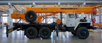
The KS-5363 pneumatic tower jib crane is used in the process of construction of structures and work with dimensional materials. Produced until 1994 in Odessa.
Design and benefits
Over the entire serial production cycle, several modifications of the KS-5363 pneumatic wheel crane, marked A, B, C, D, E, were developed and produced.
The power plant of the crane is represented by a two-stroke diesel four-cylinder and an electric power unit, two electricity generators. The kinematic diagram of the winch consists of an electric motor, gearbox, clutch, brake pads and a drum with a rim of teeth.
Advantages of the KS-5363 crane:
- performance does not decrease when operating from a diesel generator;
- simple and affordable maintenance;
- the ability to use auxiliary devices;
- turning the platform when there are no materials on the hook;
- ease of control thanks to the pneumatic wheel system;
- availability of spare parts for repairs.
A sufficient distance of the wheels from each other balances the stability of the crane and its stability when performing work operations.
Technical and cargo altitude parameters
Technical characteristics of the crane KS-5363:
- lifting rate of the load-handling device – 7.5-9 m/min;
- rate of descent – 0,7-9;
- number of turntable revolutions per minute – 0,1-1,3;
- speed of movement under its own power per hour – 20 km;
- engine – YaMZ-M204A;
- power unit power – 180 hp;
- power of the electric unit – 166 kW;
- operating weight of the equipment – 33 tons;
- counterweight weight – 4 tons.
Load-height characteristics of the KS-5363 model:
Load-height characteristics of the KS-5363 truck crane
- the largest mass of cargo on supports with the smallest and largest hook reach - 25 tons and 3.3 tons;
- the maximum weight of the lifted load without a hook at maximum and minimum reach is 2.1 and 7.5 tons;
- hook reach – 2,5-13,8;
- boom length – 15 or 17.5 m;
- load lifting height at minimum and maximum reach – 16.3 and 6.4 m;
- load capacity in motion – 14 tons.
Installation of lattice extensions 5 or 10 meters long is allowed.
Hydraulic system
The hydraulic system of the KS-5363 load-lifting crane is based on a pumping device of the NSh-32E brand with a performance parameter of 35 l/minute and a working pressure of 10.5 MPa. The system also includes cylinders, a hydraulic tank and other components.
The mechanism of operation is to supply oil to the pump from the hydraulic tank, from where it then flows to the cylinders after the distribution stage. The latter maintain pressure thanks to special valves. The created pressure and oil influence the piston, which causes it to operate.
Hydraulic system of pneumatic wheel crane KS 5363
Chassis
This part of the car is represented by several bridges. There are 4 wheels per axle, for a total of two axles. To increase the lifting characteristics, external hydraulic supports are installed, thanks to which the base of the equipment expands by 80 cm.
The rear axle drives all wheels. Equipment is transported by towing or by railway platform. In the first case, the crane needs to be folded, in the second, the wheels and boom must be removed.
Crane chassis KS-5363
Equipment
The KS-5363 crane is equipped with basic and additional accessories. Basic devices:
- boom – 15 m;
- main rope – 21 mm in diameter and 140 meters in length;
- additional rope – 21 mm in diameter and 95 m in length.
Main boom of the KS-5363 crane
Replaceable devices and their parameters:
- replaceable boom – 20-30 meters;
- replaceable boom reach – 5.5-26.3 meters;
- maximum load lift on supports – from 0.5 tons to 16.2 tons.
A boom with a lattice extension, a tower device, the reach of which can reach 17.1 m, is also installed.
Control system
Hydraulic control diagram of the KS-5363 crane
Various parts of the equipment are driven by electrical, mechanical and hydraulic control systems. Mechanical is implemented by a remote control that regulates the operation of the supports, wheels, brake system and power take-off.
The hydraulic system implements crane lifting operations. An electric motor controls the operation of the crane and winch. The safety factor is provided by the all-welded frame and drive axles of the base chassis.
Crane operator cabin
The instrument panel is located in the front part of the KS-5363 crane cabin. It is equipped with a thermometer, pressure gauge, ampere and voltmeter, switches and levers. On two sides of the panel there are controllers and power take-off devices, and on one side there is a steering control.
The KS-5363 cabin has an electric heater, it is possible to warm up the windows, a fan and windshield wipers are installed. The operator's seat is adjustable in height and degree of backrest recline.
Control cabin of the crane KS-5363
on topic: KS-5363
Leave a request to find the best price Fill out the form below and a manager will call you back and advise you on any questions and select the best price in Russia Full characteristics of the KS-5363 crane Link to the main publication
Source: https://avtokrany.guru/vidy/bashennye/ks-5363
Description of the unit
According to the passport, the KS-5363 crane is a diesel-electric design with a lifting capacity of 25 tons. It is equipped with two mechanism hooks for the main lift (25 tons), as well as auxiliary movement (5 tons). The crane also uses a grab with a pair of ropes and a bucket with a capacity of 2 cubic meters. m. Used on the crane to increase its load capacity, a multi-motor drive that powers an individual power generator set.
The speed of operation of the executive units is adjusted along the circuit from the generator to the engine by changing the supplied voltage to the main device that powers the motor.
When the crane is moving without a load, its cabin can be rotated. The installation provides a wide range for changing speeds in the movement system, not only in the working state, but also in the transport state. All equipment mechanisms are controlled using a mixed drive system.
The operator controls the main mechanisms using a push-button remote control and two command controllers. To perform gearbox shifts, control wheel turning when driving, outriggers, truck crane brake system, differential lock, pump-type hydraulics are present.
The differential or supports are controlled using the remote control on the running equipment itself; all other components are controlled directly from the operator’s cabin.
A gear pump ensures the functioning of hydraulics. Crane winches have rope handlers and spindle ends. The main fifteen-meter boom can be extended using 5 or 10 m inserts. The entire installation is equipped with a reliable tower-boom design.
The travel device has two drive axles with dual wheels. The frame has external telescopic supports, although the crane, with a small load, can do without them. Such special support attachments expand the dimensions of the base, increasing it by 0.8 m. The installation can be coupled with a coupling device to a tractor, which will move it at a speed not exceeding 20 km/h.
If it is necessary to transport equipment by rail, the boom along with the wheels is removed from it. To perform loading on a sixty-ton platform, another crane is used, which allows lifting a load of 25 tons.
Technical characteristics of the crane KS 5363
The KS-5363 crane is a jib crane that has a pneumatic wheel travel. It was developed by Odessa and rolled off the assembly line until 1990. The production of a multifunctional construction crane began in 1970.
With the help of KS-5363, installation and loading and unloading operations with loads not exceeding the maximum permissible weight are performed at construction sites. A specially developed kinematic scheme allows you to perform several operations simultaneously.
Main technical characteristics of KS 5363
Loading capacity is 10 -36 tons, depending on the initial position and modification. Standing on supports, it is capable of lifting a maximum load weighing up to 36 tons. Without deployed outriggers, the permissible weight is 14 tons, and with a load of 10 tons.
The main boom lifts the load to a height of 36.2 meters. When using tower equipment with a jib, it is possible to lift the load to a height of 50 meters. The permissible departure angle is 13 degrees.
Crane KS 5363 has the following technical capabilities:
- lift the hook at a speed of 7-9 m/min;
- lower the crane at a speed of 0.7 - 9 m/min;
- move at speeds up to 20 km/h;
- withstand support loads of up to 324 kN;
- withstand axle load up to 174 kN;
- move a 15 ton load on the move.
Main installation parameters
Several tables summarize the main characteristics of the equipment.
| Minimum | Maximum | |
| Hook reach, if telescopic supports are not installed, m | 3,3 | 25,1 |
| Hook reach when installed on telescopic supports, m | 2,1 | 7,5 |
| Boom extension from installation, m | 2,5 | 15,9 |
| Probable rise | 13.7 m | 6.4 m |
| Speed when lifting weights, m/min | 7,5 | 9,0 |
| Load lowering speed, m/min | 0,7 | 9,0 |
| Cabin rotation, rpm | 0,1 | 1,3 |
| At what speed does the installation move, km/h | 3,0 | 20 |
| Support load | 324 kN | |
| Axial load | 174 kN | |
| Small turning radius, m | 10,3 | |
| Road elevation angle | 15° | |
| Diesel engine | 180 hp | |
| Electric motor | 166 kW | |
| Front wheel track | 2.4 m | |
| Rear wheel track | 2.4 m | |
| How much does the crane weigh? | 33 t | |
| Counterweight, t | 4,0 |
Installation parameters when moving:
| Cargo weight | 14 t |
| Percentage | 56 |
| Job site slope | 3 |
Basic arrow values:
| Length | 15 m |
| Maximum build-up | 30 m |
| Jib removal | 5–10 m |
| Grab volume | 2 cu. m |
Here you can download for comparison information on the characteristics of pneumatic wheeled and crawler cranes, where, among other things, the KS-5363 is described.
The KS-5363 crane is a diesel-electric crane with a lifting capacity of 25 tons, equipped with 25- and 5-ton hooks for the main and auxiliary lifting mechanisms. The crane can use a two-rope grab with a bucket with a capacity of 2 m3. The crane uses a multi-motor DC drive powered by its own power plant. The speeds of the actuators are regulated in the generator-engine (G-E) system by changing the voltage of the main generator that supplies the engines. When moving the crane without a load, the platform is allowed to rotate. The crane has a wide range of speeds for all mechanisms, including the movement mechanism in working and transport positions. The crane mechanisms are controlled using a mixed system: hydraulic, electrical and mechanical. The main mechanisms are controlled from a remote control with buttons and two command controllers. A pump hydraulic system is provided to shift the gearbox, control the outriggers, turn the wheels, brake the travel mechanism and lock the differential. The supports and blocking are controlled from a remote control mounted on the running gear, and the remaining mechanisms are controlled from the driver’s cabin. The hydraulic system includes a gear pump NSh-32E with a capacity of 35 l/min at a pressure of 10.5 MPa. The crane winches are equipped with rope handlers and spindle limit switches. The main boom of 15 m is extended with the help of inserts 5 and 10 m long to 20; 25 and 30 m. Jib 8 and 15 m can be mounted on these booms. The crane is equipped with tower jib equipment.The running gear consists of two drive axles. The wheels of both axles are double, size 14.00-20. The running device is equipped with external hydraulic supports, but the crane can operate without them with a lower load capacity. Special attachments to the supports allow you to change the base from 4.2 to 5 m. The crane can be towed in a trailer to a tractor using a coupling device at a speed of up to 20 km/h. The crane is transported by rail with its wheels removed and without a boom - on a 60-ton four-axle railway platform. To load the crane onto the platform, another crane with a lifting capacity of 20 - 25 tons is used.
Technical characteristics of the KS-5363
crane Load capacity, t:
| .on supports: | |
| ..at the smallest hook reach | 25 / 30* |
| ..at maximum hook reach | 3,3 / 4 |
| .without supports: | |
| ..at the smallest hook reach | 7,5 / 14 |
| ..at maximum hook reach | 2,1 / 2 |
| Hook reach, m: | |
| ..least | 2,5 / 4,5 |
| ..greatest | 13,8 / 15,9 |
| Hook lifting height, m: | |
| ..at the smallest hook reach | 16,3 / 13,7 |
| ..at maximum hook reach | 6,4 |
| Speeds: | |
| ..lifting the main hook, m/min | 7,5; 9 |
| ..lowering, m/min | 0,7 — 9 |
| ..rotation speed of the turntable, rpm | 0,1 — 1,3 |
| ..crane movement by self-propelled, km/h | 3; 20 |
| Maximum support load, kN | 324 |
| Maximum axle load, kN | 174 |
| Smallest turning radius (outer wheel), m | 10,3 |
| Maximum angle of ascent of the track, degrees | 15 |
| Engine: | |
| ..brand | YaMZ-M204A |
| ..power, hp | 180 |
| Installed power of electric motors, kW | 166 |
| Wheel track, m: | |
| ..front | 2,4 |
| ..rear | 2,4 |
| Crane weight, t | 33 |
| Including counterweight, t | 4 |
* - With a boom of 15 m - 30 t, with a boom of 17.5 m - 25 t.
Load capacity when moving and the climbing angle overcome during travel in transport position
| Load capacity when moving, t* | 14 |
| Percentage of rated load capacity | 56 |
| Climbing angle of the track (without load), degrees. | 15 |
| Slope of the site during crane operation, degrees. | 3 / 1,5** |
* — Load capacity is indicated with the boom located along the axis of the crane. ** — The denominator is the permissible angle of inclination of the crane when working on outriggers.
Characteristics of the main and replaceable boom equipment of the KS-5363 crane
| Main boom length, m | 15 |
| Maximum length of extended boom, m | 25; 30 |
| Length of unsteered jib, m | 5; 10 |
| Tower boom equipment: | |
| ..maximum length of additional boom, m | — |
| ..maximum tower length, m | — |
| Grab capacity, m3 | 2 |
| Main boom of the KS-5363 crane |
The power plant of the KS-5363 pneumatic wheel crane consists of a four-cylinder two-stroke diesel engine 6 of the YaMZ-236 brand, an electric motor 2 of the A2-72-4 brand 380 V AC for operation from an external network, two DC 220 V generators: the main 10 brand DK-309B and auxiliary 1 brand P-62. 3 - 4 - 8 gear pump 5 of the NSh-10E brand with a working pressure of 7.5 MPa is connected to the power plant through a belt drive system
| Power plant of the crane KS-5363 |
Load winches of the main lift of jib cranes are designed for lifting and lowering loads, auxiliary lift winches are designed for lifting smaller loads on a jib or grab. The kinematic diagrams of the main and auxiliary lifting winches of the KS-5363 crane are not fundamentally different from each other.
The main lift winch is driven by an electric motor 1 . The output shaft of the electric motor is connected to the input shaft of the three-stage gearbox 5 by a gear coupling 2 . On the input shaft of the gearbox, a shoe brake pulley 3 , controlled by a short-stroke electromagnet 4 . The four gearbox shafts are supported on its housing using ball bearings. The gearbox contains three pairs of cylindrical helical gears. The gearbox is connected to the drum 8 by a gear coupling 7 , one half of which is fixed to the output shaft of the gearbox, the second - to the drum shaft. Gear coupling 7 simultaneously serves as one of the supports for the drum axis. The drum axis is supported on one side by means of double-row roller bearings by support 9 . On the other side, the axis is connected by a gear coupling 7 to the output shaft of the gearbox.
| Main lift winch | Kinematic diagram of the cargo winch for auxiliary boom lift |
The auxiliary lift winch is driven by electric motor 1 , power from the electric motor to drum 4 is transmitted through a three-stage gearbox with spur gears - gears 12 - 11 , 10 - 6 , 2 - 5 . The engine and drum are connected to the gearbox through gear couplings 14 . A TKP-300 brake is installed on the input shaft of the gearbox. A limit switch 9 to the output shaft of the gearbox through gear transmission 7 - 8 .
The kinematic diagram of the boom winch is somewhat different from that discussed above. The differences are that on the input shaft of the gearbox there is not one brake, but two 11 and 14 type TKP-200, the winch mechanism is equipped with a rope handler 7 , driven by a single-start worm 6 through a chain drive 4 - 5 , in which one sprocket is located on the worm 6 , the other on the drum shaft 3 , the boom winch is not equipped with a limit switch.
| Kinematic diagram of the boom winch |
| Kinematic diagram of the turning mechanism | Rotation mechanism (fig.) |
The turning mechanism of the KS-5363 crane consists of an electric motor 10 , a gear reducer with gears: bevel 7 - 6 and cylindrical 11 - 3 , 5 - 4 ; runner gear 2 and ring gear 1 . The engine is connected to the gearbox by a chain coupling 9 . On a common shaft with one of the coupling halves there is a permanently closed shoe brake 8 type TKP-200.
The movement mechanism consists of an electric motor 18 , a two-speed gearbox (gears 4 - 13 and 2 - 15 ) and two axles: front A and rear B. The front axle is steered, the rear axle is unsteered. The front and rear axles are connected to the gearbox by cardan shafts. From the cardan shafts, power is transferred to the axles to the main bevel gears 6 - 7 . The transmission systems in the front and rear axles are the same. On a common shaft with bevel gear 7, 12 is rigidly mounted , which meshes with gear 11 , rigidly connected to the differential housing. The housing contains four bevel gears. Two gears 9 are rigidly mounted on the axle axles, the other two (satellite gears 10 ) are mounted on the console axles of the differential housing. Thus, when gear 11 begins to move, the differential housing rotates along with the satellite gears, which, being meshed with gears 9 mounted on the axle shafts of the bridge, transmit power to the wheels. The differential device makes it possible to drive the road wheels at different speeds at a constant speed of the driveshaft. This property of differential gearing is used when the crane moves around curves, where the outer wheel travels a longer distance than the inner wheel, and therefore the outer wheel must rotate at a higher frequency than the inner wheel.
| Kinematic (above) and structural (below) diagrams of the movement mechanism of the KS-5363 crane |
The gearbox is used to change the speed of movement of the crane. The gear shaft 19 is connected to the electric motor and power is taken from it through the right gear to the intermediate shaft 21 . On the input shaft 15 , gears 16 and 26 and are in constant mesh with 21 . When the gear shaft 19 , these gears also rotate. The power to shaft 15 from gear 16 or 26 is taken through a gear 17 , which has a splined fit on this shaft. The drive and control of the gear coupling are hydraulic (the mechanism in the figure is disconnected from the gearbox housing). When the piston 7 located in the hydraulic cylinder 6 5 moves accordingly and through the roller 10 moves the fork 12 , pivotally connected to the gear coupling 17 . Shaft 15 is connected directly to the rear axle driveshaft. Power is taken from the shaft 15 to the driveshaft of the front axle through a gear coupling 14 . When the first gear is engaged, the gear coupling 17 connects the gear 16 to the output shaft and at the same time the plunger moves the gear coupling 14 to the left and engages the front axle. When the second gear is engaged, gear coupling 17 connects gear 26 . At the same time, plunger 13 moves clutch 14 and disengages the front axle. To prevent the electric motor of the travel mechanism from turning on when the gear is not engaged, electrical blocking is provided with limit switches 4 .
| Crane gearbox KS-5363 |
Rear axle of crane KS-5363 of automotive type; its basis is a cast crankcase 21 with axles attached to it. The crankcase is rigidly attached to the fixed frame with bolts. Hubs 4 and 13 are mounted on the crankcase axles on tapered roller bearings 10 . 1 with tires 31 are mounted on the hubs 13 . The wheels receive rotation from the main gear 23 through the axle shafts 32 . The running wheels of the rear axle are equipped with shoe brakes, the brake pulleys 26 are mounted on the hubs 13 of the running wheels, and the brake pads 15 are mounted on brackets welded to the crankcase axles 21 . Braking of the wheels is carried out from the pneumatic cylinder 20 through the lever 18 and the fist 16 (when the fist is turned to the left, the pads diverge and the linings 17 are pressed against the inside of the pulley 26 ). 25 to the crankcase 27 on studs .
| Rear axle of crane KS-5363 |
The figure below shows the shoe brake and its mounting on a tap to the housing 2 of the rear axle. The brake pulley 16 is secured with bolts 26 and pins 27 to the main gear shaft 25 . Brake pads 14 together with levers 13 are hinged to the crankcase 2 . The brake is activated using hydraulic cylinder 23 and released using springs 4 and 11 . The gap between pulley 16 and brake pads 14 with the brake open is adjusted with bolt 10 .
| Rear parking brake of crane KS-5363 |
The main gear includes a bevel gear 13 - 21 , a spur gear 22 - 10 , a differential 8 - axle shaft 1 . Gear 13, through sleeve 14 , rests on tapered bearings 12 and 20 . Gears 21 and 22 sit on a common shaft supported by tapered bearings 23 . The bearings are enclosed in a cup 24 , pressed into the housing 25 of the main gear. The differential is enclosed in a bowl 6 , supported by bearings 3 . The differential includes semi-axial gears 5 and satellite gears, freely sitting on a cross 7 mounted in the differential cup. When gear 10 rotates, the differential bowl and crosspiece rotate, and, consequently, the differential satellite gears 8 . They are in mesh with the side gear 5 , which has a splined fit on the axle shaft 1 . 5 and axle shafts 1 rotate . The differential allows the axle shafts to rotate at different speeds, which allows the crane to move around curves. When the crane moves in a straight line, the satellite gears do not rotate around their own axis. When turning, the inner radius of the crane is smaller than the outer radius, so the inner wheel travels a shorter distance compared to the outer one. Accordingly, its rotation speed should be lower than the rotation speed of the outer wheel. In this case, the satellite gear begins to rotate around its own axis and imparts an additional rotation speed to the semi-axial gear 5. Accordingly, the speed of the pneumatic wheel connected to this semi-axle increases.
| Main gear of crane KS-5363 |
The front axle of the crane is also of the automotive type. The main gear of the front axle is the same as that of the rear axle. Unlike the rear axle, the front axle is steerable. This caused some distinctive design features. These include, first of all, the use of a steering knuckle 5 , which ensures rotation of the wheels in the horizontal direction and movement in the vertical direction. The turning mechanism is driven by hydraulic cylinders 10 through their rods 8 . Since the axle 2 can move relative to the crankcase, composite axle shafts (external and internal) with a hinged connection are used. The hinge design is visible in the figure. At the junction of the axle shafts 1, at their mating ends, special heads are made with a cylindrical bore for the fist 3 of the hinge. There is a recess in the fist for the 4th hinge disc. This design of the hinge allows torque to be transmitted to the wheels through the axle shafts when they intersect each other at different angles within specified limits. The outer running wheels of the front axle are not driven; they are mounted on bronze bushings and rotate freely relative to the internal running wheels. In difficult road conditions, the outer wheels are connected to inner leads, which are mounted on the wheel flanges and secured with bolts. This reduces rolling resistance when the crane passes along curved sections of the track.
| Front axle of crane KS-5363 |
The device for towing the crane in a trailer with a tractor is mounted on the eye of the running gear and consists of a drawbar 9 , a rod 2 , a pin 13 and a spring 12 . To mount the device, a special bracket is welded to the fixed frame of the crane. Lever 6 hingedly attached to it using axis 5 drawbar 9 using axis 7 . The drawbar is connected by a rod 2 to the steering knuckle 4 of the front axle; the rod is connected to the steering knuckle using an axis 3 , and to the drawbar using a spherical pin 1 . To dampen inertial loads, pin 13 is connected to drawbar 9 12 mounted in it . The wheels are turned on curves by turning the drawbar with a horizontal plane. To freely connect the cavities of the hydraulic cylinders for turning the wheels when transporting the crane in a trailer with a tractor, a valve 8 .
| Crane towing device KS-5363 |
The outriggers consist of swing arms 6 , hydraulic cylinders 7 with rods 9 , heels 10 or stands 12 . To mount the supports, brackets are welded to the fixed frame 1 . Levers 6 outriggers are connected to the brackets using axes 5 . 7 with retractable 9 are mounted on the rotary arms of the . Depending on operating conditions, the rods can rest on a heel 10 or a stand 12 . To uniformly distribute pressure on the ground and reduce the values of their specific indicators, the heel or stand is supported by wooden blocks (pads). With the help of outriggers, the non-rotating frame is hung on them and brought to a horizontal position. The operation of the outriggers is controlled from station 16 using a control valve 15 . The height position of the hydraulic cylinders, after the fixed frame is suspended and brought into a horizontal position, is fixed with nuts 8 .
| Outriggers of crane KS-5363 |
Electrical equipment of a crane with multi-motor DC drive KS-5363
The power plant of the KS-5363 crane consists of a YaMZ-236 diesel engine and two DC generators with a voltage of 220 V. To power the electric motors of the winches and the movement mechanism, a DK-303B electric motor with a power of 50 kW is used, which acts as a DC generator. An auxiliary generator P-62 with a power of 11 kW is used to power the electric motor of the turning mechanism, control circuits, excitation and lighting. The turning mechanism motor can also be powered from the main generator. The crane uses crane-type DC electric motors with increased overload capacity and mechanical strength. To operate the crane from an external network, an A02-72-4 380 V AC electric motor is used. To start the diesel engine and power its instrumentation, as well as to power the lighting and alarm circuits, two 12 V batteries are installed on the crane; The batteries are recharged from a separate generator driven by a diesel engine. The same batteries power the brake light circuits and two fans for air circulation in the driver's cabin. The rotation speed of the turning mechanism motor is controlled by a resistor. The operating speed of the remaining electric motors is adjusted by changing the voltage of the main generator that powers the engines, in accordance with the operating instructions for the crane. The crane mechanisms are controlled using command controllers. To start the boom winch motor, press the button and move the controller handle to the “Up” or “Down” position, which corresponds to raising or lowering the boom. Stop the boom by moving the handle to the zero position and pressing the “Stop” button. The turning mechanism is controlled using a command device and a switch acting on the auxiliary generator. To increase the accuracy of element alignment during installation work, the main generator and the command controller of the cargo winch are used. The swing mechanism controller handle is set to the 5th position and then the speed is adjusted using the winch controller. To turn to the right, the handle is moved to a position corresponding to lifting the load, and to turn to the left, to lower the load. Stop the mechanism by moving the handles of both controllers to the neutral position. Combining movements with the specified speed control is not permitted. The movement mechanism is controlled using the same devices. The engine is started and accelerated through the “Start” button and the controller handle by smoothly moving it from the 1st (lower speed) to the 5th position (higher speed). Movement forward or backward depends on the direction of rotation of the handle “Right” or “Left”. To change the speed of movement from 1st to 2nd, you must perform the following operations: set the controller handle to the neutral position; set the gear knob to 2nd speed; press the “Start” button and smoothly turn the controller handle in the required direction. To perform electric braking while the crane is moving, the controller handle is moved to the neutral position and the first button, “Brake,” is pressed sequentially, and then the second button and held. By releasing the second button, the braking of the crane is automatically stopped. In order to soften the effect of dynamic braking at speeds above 7 km/h, first slow down the crane using a hydraulic brake (brake) and only then operate the second button. To stop the crane for a short time, move the controller handle to the neutral position, press the “Stop” button and turn on the brake of the travel mechanism. In case of a long stop, use the parking brake. To operate at sub-zero temperatures, the cabin is equipped with an electric furnace and windshield heaters.
Cabin and crane control panel
Attached to the front of the windshield is an instrument panel on which ammeters, voltmeters, switches, switches, a thermometer and a pressure gauge are mounted. To the left and right of the board there are command controllers for controlling the crane mechanisms, devices for changing the speed of the crane and controlling the rotation of the wheels. All of the above instruments and devices make up the crane control panel. In addition, the cabin is equipped with an electric furnace for heating at subzero temperatures, heaters that prevent fogging and icing of the windows, a fan for operation in the summer, and windshield wipers. At the control panel on the floor of the cab there is a driver's seat, the height and distance of which from the control panel can be adjusted. The front and side walls of the cabin are partially glazed, which allows for all-round visibility and monitoring of working equipment and working parts.
| Control cabin of diesel-electric crane KS-5363 | Hydraulic control diagram of the KS-5363 crane |
The crane is equipped with a load limiter OGP-1. To limit the lifting height of the hook, a spindle-type limit switch is used, which is triggered after turning the cargo winch shaft to a certain angle. The switch is connected via a gear to the gear of the cargo winch shaft. The limiter is adjusted when changing working equipment or when replacing a cargo rope. To prevent the boom from tilting onto the turntable, a telescopic stop is installed on the crane.
| Telescopic stop |
| Photo gallery of crane KS-5363 |
| Back to the page “Cranes. Descriptions and technical specifications" |
| The author of the site would be grateful for any information and photographs of this crane. Email |
| Copyright © 2002-2010 TechStory.ru |
home
Hydraulic system
The hydraulic drive of such a crane model as KS-5363 is entirely based on the operation of the pumping device model NSh-32E. The system also includes a hydraulic tank, cylinders and other components necessary for reliable operation.
Operation is ensured by supplying oil of a certain viscosity from the hydraulic tank to the pump. This pump directs the fluid to the cylinders, bypassing the distribution stage of the movement. Due to the presence of valves in the cylinders, the required pressure is maintained there. The piston moves under the influence of oil.
Basic equipment
The working elements of KS-5363 can be divided into main and replaceable elements. The main equipment consists of a lattice boom and ropes. In addition, there are interchangeable booms, jib devices and tower-boom devices.
Be sure to read: Characteristics of the KKS-10 gantry crane
The crane is equipped with a main boom, the length of which is 15 meters. The rope used in the boom has a diameter of 21 mm and its length is 140 meters. The auxiliary rope has the same diameter, while its length reaches 95 meters.
Chassis
The movement mechanism is provided by generating torque in several bridges. Each axle (of which there are two in the cart) rotates 4 wheels. To increase the load-carrying characteristics, outrigger supports with a hydraulic drive are additionally installed. Thanks to them, the dimensions of the equipment expand, reaching a parameter of 5 m.
The rear axle ensures rotation of all wheels. To transport equipment, they use the towing method or loading a crane onto a railway platform. For the first option, the installation is folded; when loading, it is necessary to additionally remove the wheels with the boom.
Replacement equipment
Replacement equipment is installed instead of the main one and allows you to perform other tasks. Depending on this, the technical capabilities of the crane change.
Replacement equipment consists of the following elements:
- extended booms;
- jib arrows;
- tower-boom devices.
An extended boom and a jib boom have a length of 20-30 meters. At one time, the tower-rifle device was only 10 meters long. Moreover, unlike other additional equipment, the tower has a height of 20 meters.
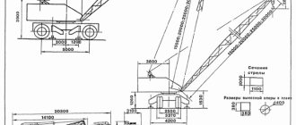
Faucet dimensions
Lifting equipment
Basic as well as additional accessories are provided as structures for the crane modification KS-5363. The main components include the following devices:
- fifteen-meter boom supplied in the kit;
- main rope of extended boom;
- auxiliary rope.
The replacement devices supplied with the unit are as follows:
- replaceable booms that can be added, allowing you to extend the main structure by 5 or 15 m;
- The reach of the replacement boom is possible within the range of 5.5–26.3 m.
A boom with a lattice extension is also installed. Its reach can reach 17.1 m.
Modifications
The Yanvarets plant produced the following equipment options:
- The basic version of the machine was the KS-5363 model, intended for operation in temperate climates with air temperatures of -40...+40°C. Load capacity is 25 tons.
- On a separate order, the KS-5363HL version was produced, adapted for operation at temperatures down to -70°C. The materials from which the loaded elements are made have been changed. Additional thermal insulation of the driver's cabin has been introduced.
- A modernized version of the KS-5363A, characterized by modified components that have an increased service life and simplified maintenance.
- A further development was the KS-5363B crane, equipped with a special device to increase the lifting capacity to 40 tons. The machine can operate as a tower crane with a jib 15 m long.
- Modification of KS 5363B, which uses a different scheme for installing counterweights on an external frame. The design of the extension inserts on the boom has been changed. Improved versions with a lifting capacity of 36 tons and improved technological parameters are designated KS-5363D and KS-5363E.
- Army vehicles KS-5363M and AM. The difference between the machines is the increased positioning accuracy of the working parts. The equipment was used in army warehouses, including for loading strategic nuclear weapons.
- The last production vehicle was the KS-5366, which featured hydraulic drives in controlling the boom angle and in the turret rotation mechanism. The crane was produced until 1994.
Management organization
Each piece of equipment operates through a mechanical system, adjustable electrical or hydraulic equipment. The first option is implemented by a remote control that ensures the operation of the wheels, outriggers, brake system, and power take-off.
The electric motor ensures the operation of the winch. Its strength reserve is transferred to the drive axles of the main chassis in the form of an all-welded frame. The hydraulic system provides all lifting operations of the installation.
Crane control
Hydraulic control circuit KS-5363
The machine, weighing more than 30 tons, is equipped with three systems: hydraulic, mechanical and electrical. Hydraulics is represented by a set of mechanisms that ensure the normal operation of lifts. Mechanics are responsible for the operation of the gearbox, wheels, supporting structures and brakes.
The electrical system is based on DC generators. The operation of the winch and movement of the KS-5363 is provided by an electric motor. The motor and generator form a single system; a pair of batteries is used for uninterrupted operation of the diesel engine.
With the help of a lattice-type main boom and an additional jib, loads from 3.3 tons can be lifted.
A one-piece base and a pair of chassis axles are used to ensure high-strength installation.
Driver's cab
The front area of the self-propelled crane cabin is equipped with a dashboard. It contains a pressure gauge with a thermometer, a voltmeter with an ammeter, various levers, and also switches. On the sides of this panel there are controllers with visual instruments displaying power take-off. The steering control of the structure is also located here.
The cabin is equipped with an electric heater, it is possible to warm up the windows in cold weather, there are windshield wipers and a fan. The operator's chair is adjustable both in height and in the angle of reclining of the backrest. Since the front (together with the sides) wall is partially glazed, the operator is provided with an all-round view, allowing him to observe the operation of the equipment and all components.
The installation contains a load limiter of the OGP-1 brand. To prevent the lifting height of the hook from exceeding the permissible parameters, a spindle limit switch is used. It is triggered when the winch shaft rotates at a set angle.
With a gear, such a switch is connected directly to the winch itself. The limiter must be adjusted when repairs are made to the working equipment or load rope. To prevent the possibility of the loaded boom tilting, the equipment must be provided with a telescopic stop.
hydraulic system, chassis, device, diagram
The KS-5363 lifting machine was produced until 1994 in Ukraine. The manufacturer was an Odessa company.
Advantages and features of the KS-5363 jib crane
The significant advantages of the crane are:
- the device does not lose efficiency when operating from the built-in diesel generator;
- simplicity and low cost of service;
- allows the use of a grab with a bucket;
- platform rotation when there is no load on the hook;
- the pneumatic wheel system makes the crane very easy to operate;
- balance and stability are ensured by wheels that are sufficiently far apart from each other.
- Availability of spare parts, which makes the KS-5363 crane easy to maintain.
This equipment on pneumatic wheels is one of the most popular in the construction field. KS-5363 is actively used for loading and unloading large goods, as well as directly for the construction of buildings.
Over the entire production cycle, the Ukrainian plant supplied the markets with a whole host of modifications, which were marked with the letters A, B, C, D, E. The symbols M and AM were sometimes added to the modification letter designations. This is an indication that these models of jib cranes were produced under the exclusive order of the army. They were subjected to strict quality control and testing with the personal participation of representatives of the defense department. Such close attention was explained by the fact that the KS-5363 was often used to work with particularly important weapons.
Device
The various mechanisms of the equipment are controlled by three systems:
- mechanical;
- hydraulic;
- electric.
Mechanical control is a remote control responsible for the functioning of the brakes, gearbox, wheels and supports.
Hydraulic control is a complex of elements responsible for the operation of lifting equipment.
Crane diagram KS-5363
Electrical control is based on DC generators. The electric motor is responsible for operating the winch motors and for moving the crane. The generator and diesel engine are connected into a system, and two batteries are used to operate the diesel engine. To lift loads, a lattice-type main boom and an additional 15-meter jib are used. Particular strength of the loaded structure is ensured by the solid frame and two drive axles of the chassis.
Hydraulic system
The KS-5363 hydraulic control system is based on the NSh-32E gear pump. Its main characteristics:
- productivity 35 l/min;
- pressure 10.5 MPa.
In addition to the pump, important components are the hydraulic tank, pump, accumulator, pipelines and actuator cylinders. The action begins with oil flowing from the hydraulic tank into the pump. From there it enters a special distributor, and through it to the actuator cylinders.
The distributor is equipped with a valve that provides pressure in the cylinder. In it, the oil acts on the piston, causing it to move and operate the mechanism.
Chassis features
The chassis of the KS-5363 vehicle consists of a pair of axles. The system includes 8 wheels, 4 per axle. The rear axle provides drive to all wheels, and the front axle only to the internal ones. There are also remote-type hydraulic supports here. They increase the base of the device by 80 centimeters and serve to increase the load capacity.
Front axle
The crane can be transported in two ways:
- towing with a tractor, and then the mechanism must be folded;
- on a railway platform, and then the boom and wheels should be removed.
Basic technical specifications
Technical characteristics of the KS 5363 pneumatic wheel crane are presented in the table:
| Characteristics | Unit measurements | Data |
| Crane height | m | 3,9 |
| Tap length | m | 20,3 |
| Crane width | m | 3,3-4,2 |
| Crane weight | T | 33 |
| Load capacity with hydraulic supports | T | 3,3-30 |
| Load capacity without supports | T | 2-14 |
| Hydraulic support load | kN | 324 |
| Wheel axle load | kN | 174 |
| Travel speed | km/h | 19,5 |
| Hook Reach | m | 2,5-15,9 |
| Lifting height | m | 6,4-16,3 |
| Lifting speed | m/min | 0,7-9 |
| Engine model | YaMZ-M204A | |
| Engine power | hp | 180 |
Equipment, its types and technical parameters
The KS-5363 equipment is equipped with basic and replacement equipment. The main one includes a lattice boom and ropes, and the interchangeable one includes extended booms, devices with jib, as well as tower-boom elements.
Basics
| Characteristics | Unit measurements | Data |
| Boom length | m | 15 |
| Main rope diameter | mm | 21 |
| Main rope length | m | 140 |
| Auxiliary rope diameter | mm | 21 |
| Auxiliary rope length | m | 95 |
Replaceable
| Characteristic name | Extended booms | Jib arrows | Tower-boom device | |
| On the main suspension | On auxiliary suspension | |||
| Replaceable boom length, m | 20 — 30 | 20 — 30 | 20-30 | 10 |
| Tower height | — | — | — | 20 — 30 |
| Replaceable boom radius, m | 5,5-26,3 | 5,5-14,2 | 13,4-23,7 | 10,5 — 17,2 |
| Load capacity with supports, t | 0,5 — 16,2 | 1 — 13,5 | 0,5 4,2 | 1,9 — 5,5 |
| Load capacity without supports, t | 0,3 — 6 | 0,5 — 5 | 0,5 — 2 | 0,4 — 3,5 |
| Hook lifting height, m | 10,2 — 23,9 | 15 — 28,9 | 16,4 — 30,5 | 22,1 — 38,2 |
| Lifting and lowering speed, m/min | 1,5 — 11 | — | — | 3 — 22 |
magistraltrade.ru